Electronics
Initial Motor Control Board
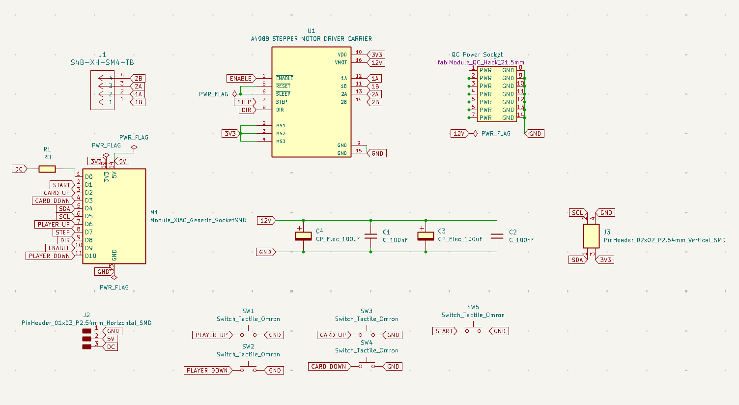
An essential part of my final project is a board to control the card dealer. Following the pin requirements list above, I designed a schematic for the board in KiCad.
The schematic has the following features:
In KiCad I made a schematic with these features.

Schematics for control board
This schematic passed the electrical rules checker
I then made a PCB design from this schematic in KiCad

PCB for control board
This design passed the design rules checker.
Files for the initial Control Board KiCad
I fabricated the board, and first tried a simple motor control with the following code:
// Define pin connections & motor's steps per revolution
const int dirPin = 9;
const int stepPin = 8;
const int stepsPerRevolution = 200;

void setup()
{
    // Declare pins as Outputs
    pinMode(stepPin, OUTPUT);
    pinMode(dirPin, OUTPUT);
}
void loop()
{
    // Set motor direction clockwise
    digitalWrite(dirPin, HIGH);

    // Spin motor slowly
    for(int x = 0; x < stepsPerRevolution; x++)
    {
        digitalWrite(stepPin, HIGH);
        delayMicroseconds(2000);
        digitalWrite(stepPin, LOW);
        delayMicroseconds(2000);
    }
    delay(1000); // Wait a second

    // Set motor direction counterclockwise
    digitalWrite(dirPin, LOW);

    // Spin motor quickly
    for(int x = 0; x < stepsPerRevolution; x++)
    {
        digitalWrite(stepPin, HIGH);
        delayMicroseconds(1000);
        digitalWrite(stepPin, LOW);
        delayMicroseconds(1000);
    }
    delay(1000); // Wait a second
}
The motor does move back and forth as expected. The motor hums in periods, but doesn’t move back and forth. I need to evaluate if there is a problem with my board, or whether there is a problem with my design.
Refined Motor Control Board
Following initial testing, I reconsidered the design for my motor control board. In this, I changed the design to feature:
- 3 buttons
- A socket for the 12V power board breakout
- A socket for Xiao RP2040
- Two sockets for A4988 motor control boards
- Connection for I2C (with 5V)
- 3 pins for a possible DC motor
- Two 4 pin sockets to connect stepper motors
Notably, my primary design will now feature two stepper motors. One will control rotation of the main case, and the other will control the roller to distribute cards.
This is the board used in my final project.
Schematic for the final board

PCB for final control board
KiCad files for this board.
QC Power Board
As the stepper motors need more voltage than can be supplied via the microprocessor, I also made a QC hack power board. The QC (Qualcomm Quick Charge) board can supply up to 20V with an appropriate USB power supply. The output voltage can be adjusted via a potentiometer on the board.

QC power had board
KiCad files for the power board.
This board includes an USB-A connection, which is connected to a power brick that supports the QC protocol.
Fabrication
The boards were milled on the lab Roland MX-20 using the processes described in Electronics Production week. Components were soldered on. The main control board has sockets for the A4988 control chips, the QC power breakout, and the Xiao microprocessor.

Main control board after milling

Parts for the final project, including a view of the board with soldered components