8. Computer controlled machining
Browse through the NuEval Handbook to review the evaluation criteria.
Group Assignment
Safety training
Before using the CNC machine all users undergo safety training.
The most important part of the safety training is understanding that there can be a fire hazard, a risk of damage to the machine and a risk of injury to people so keeping an eye on the machine at all times is crucial.
- Always keep hands, body-parts and clothing away from all moving parts
- Always use eye protection while the machine is running
- Use ear protection while the machine is running
- Use gloves while handling stock
- Do not leave the machine while it is running, always keep an eye on the machine
- Make sure the vacuum is turned on
- Do not use the machine if you are tired
- Do not use the machine if you are alone in the lab
- During the training the users also learn how to use the machine:
During the training the users also learn how to use the machine:
- How to turn on and off the machine
- How to set up the machine
- How to use the software
Test runout, alignment, fixturing, speeds, feeds, materials, and toolpaths for your machine
Anna
Albert
We split the group work. I evaluated the effects of kerfs on joints.
Design of test piece
Following similar steps use for my individual design work, I made a test piece. Using parametric design, I made a piece that had three slots. The middle one has width of the piece thickness. On one side, it has a kerf of +0.5mm, and the one on the other is -0.5mm. The slots are 1/2 the piece height.

I didn’t know the thickness of the wood piece when designing. In the lab I found a piece for use which was 21mm (measured with calipers). I put that into the design in Fusion, and then exported a DXF file for the face.
In VCarve, opened the piece and then duplicated the piece, as I wanted to fit two pieces together. I also added 3mm dog bones in VCarve to the bottom of the slots. I also added fillets to the tops of the slots to make the easier to put together.
I then exported the Gcode from VCarve for import into the Shopbot software.
Fabrication of test piece
This used the same steps note in my individual fabrication work for the week.
While following the same steps noted on the individual work, I encountered an problem as noted below.
Note: I did this work first, though the specific works steps are noted. I used the lessons from a mistake (see below) for better cutting on the individual project work.
I worked with two passed of cutting. First using a 6mm downcut bit, I cut 3mm into the piece in a single pass. Then, with a 6mm upcut bit, I made 7 additional passes, with the final cut set to 0.3mm beyond the bottom of the piece.
I did the cuts with the shopbot, which appeared to run fine. I then used a chisel to sever the tabs.

Severing tabs with a chisel
At this point, I noted an issue. The piece did not come free, and with closer examination, the piece was not cut all the way through. I double checked the settings, and all appeared to be right. It appeared that I failed to tighten the bit sufficiently, and the bit moved up slightly. This caused the piece to not be fully cut through. A thin onion skin layer was left.
I took the piece up, and used a knife to cut the onion skin which was left. With this, I was able to free the cut pieces.

Back side of piece, which is not fully cut through
When fully cut out, the plywood was messy.

Pieces cut out, and messy
I used a sander to clean up these splintery bits. Ended in uneven wood on the spurs, which wouldn’t be good for a final piece. However, for a test piece this is fine.
The fit between the -0.5mm kerf was too small, and the +0.5mm was a bit loose. The slot without a kerf was a tight fit, but required a little coaxing with a rubber hammer to get it all the way. Since one wouldn’t want a piece to come apart, this is fine.

Using hammer to get together
The final piece came together nicely

Test pieces joined
From this, It appears that there is no need for any kerf, and pieces can be put together without any need for glue or fasteners. With the tight fit, pieces should stay together.
Evert
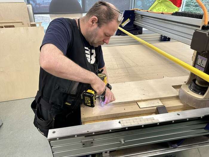
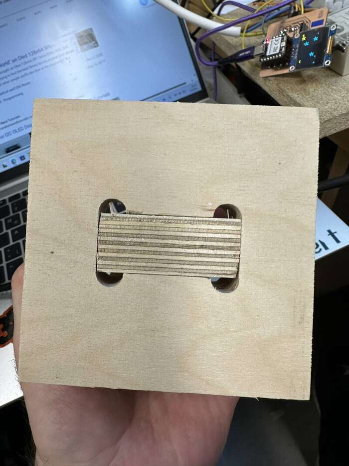
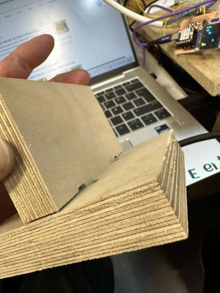
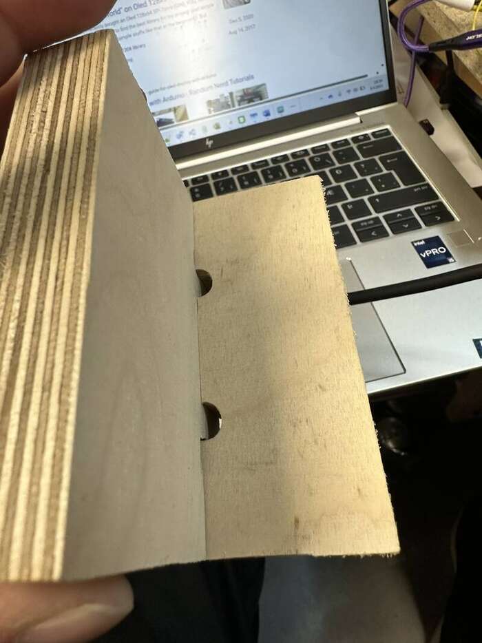
My part in this week group assignment was to document and test the run out and the alligment of the shopbot machine . i made little test pice to test this out. to test the alignment i cut out square hole in the wood. and to test out the runout i made to pieced that woukd be joint togeather without any fasteners.
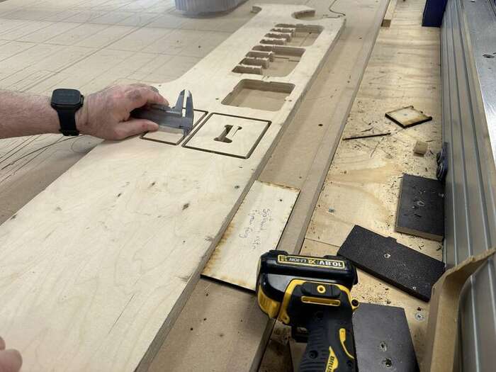
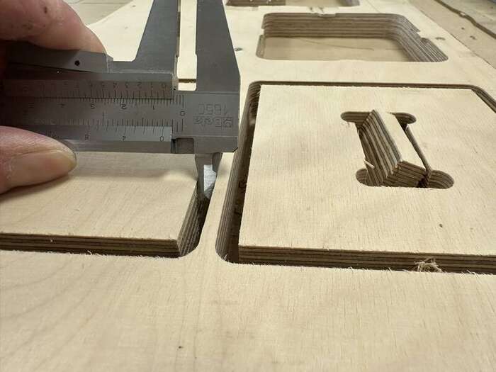
Like we can see on the last to pictures we measure 6mm as this was cut out with 6mm endmill we now know that there is no runout on the machine if it was runout we would most likely measure more than 6mm gap there, we can also see on this pictures that the peice is cut out in good and nice squere whit good corners so then we can be quite sure the alignment on the machine is good.
Here are some picture of the final test.
Magnus
Joint in AutoDesk Fusion CAM
For this week’s group assignment I took one of the joints I recreated in the group assignment from Week 4. “Computer controlled cutting”. This time I’ll size it up and cut it on the ShopBot. I’m using AutoDesk Fusion’s CAM instead of VCarve.
I copied the pinned joint component from the file to a separate one. Adjusted the parameters to match the material thickness I’m using and sized it proportionally.
Here are the parameters for the adjusted pinned joint:
| Name | Unit | Expression | Description |
|---|---|---|---|
| TLen | mm | 120 mm | Total Length |
| TWid | mm | 120 mm | Total Width |
| MatT | mm | 18 mm | Material Thickness |
| Kerf | mm | 0 mm | Kerf |
| JDep | mm | TLen/2 | Joint Depth |
| ToolDia | mm | 6 mm | Diameter of cutting bit |
| Dogbone | mm | ToolDia + 2 mm | Dogbone Diameter |
And here is the joint as set up in Fusion:

I laid out the parts in the same way I would cut them.
Then I switched from “Design” over to “Manufacture”

First step here is going through the setup. This is where you define the machine type, coordinate system(orientation) and stock size.

I’m doing this on the ShopBot PRSAlpha 120x60 we have here in Reykjavík. The machine is set to operate with X Y Z origin relative to the near-left corner when looking at the machine relative to the control console. In this case I set the orientation as “Model Orientation” the origin as “Stock bbox point” and define the point along the stock I also added a 5mm stock offset in the “Stock” tab. Fusion adds a 1mm top offset by default. If your design is the This is mostly to offset the start of the cut from the zero point. The material stock I was using was significantly larger than the job I was doing. If the margins from stock to cut are tight you can draw a copy of your stock and define it as your stock in Fusion(There’s an option under the setup dropdown to “Draw Manufacturing Model”, which is a model that only affects the manufacture workspace). This can help with positioning screws and getting a more accurate zero position. Lastly. I selected the four things I wanted to cut in “Model”. You can also set the program name and number in the “Post Process” tab.
Once finished with the setup I move to making the toolpaths. Make sure to have the setup you just created selected with the dot like so:

For this project I only need profile cuts. I’ll be doing two of them, One is a downcut 3mm into the material and the other is an upcut which goes all the way through the piece with tabs.
I used a 2D Contour for this.

This is the first tab where I define the tool I’m using for the cut

In this case I just based the settings off of the settings I already used in the Individual Assignment in VCarve. Those were based off the Fablab Speeds and Feeds Tool
