5. 3D Scanning and printing
This week's assignment focused on 3D objects. The objective was to design a 3D piece that was articulated, print it with the parameters we wanted for the result of our printing. And finally the scanning of a 3D object to obtain its computerized model and optionally, print it.
To understand the principles of 3D printing, research was conducted in a group assignment, exploring the different 3D printing machines, the material for printing, printing limitations such as expansion, the importance of supports, or the types of infill. The group assignment page is as follows:
Articulated part design
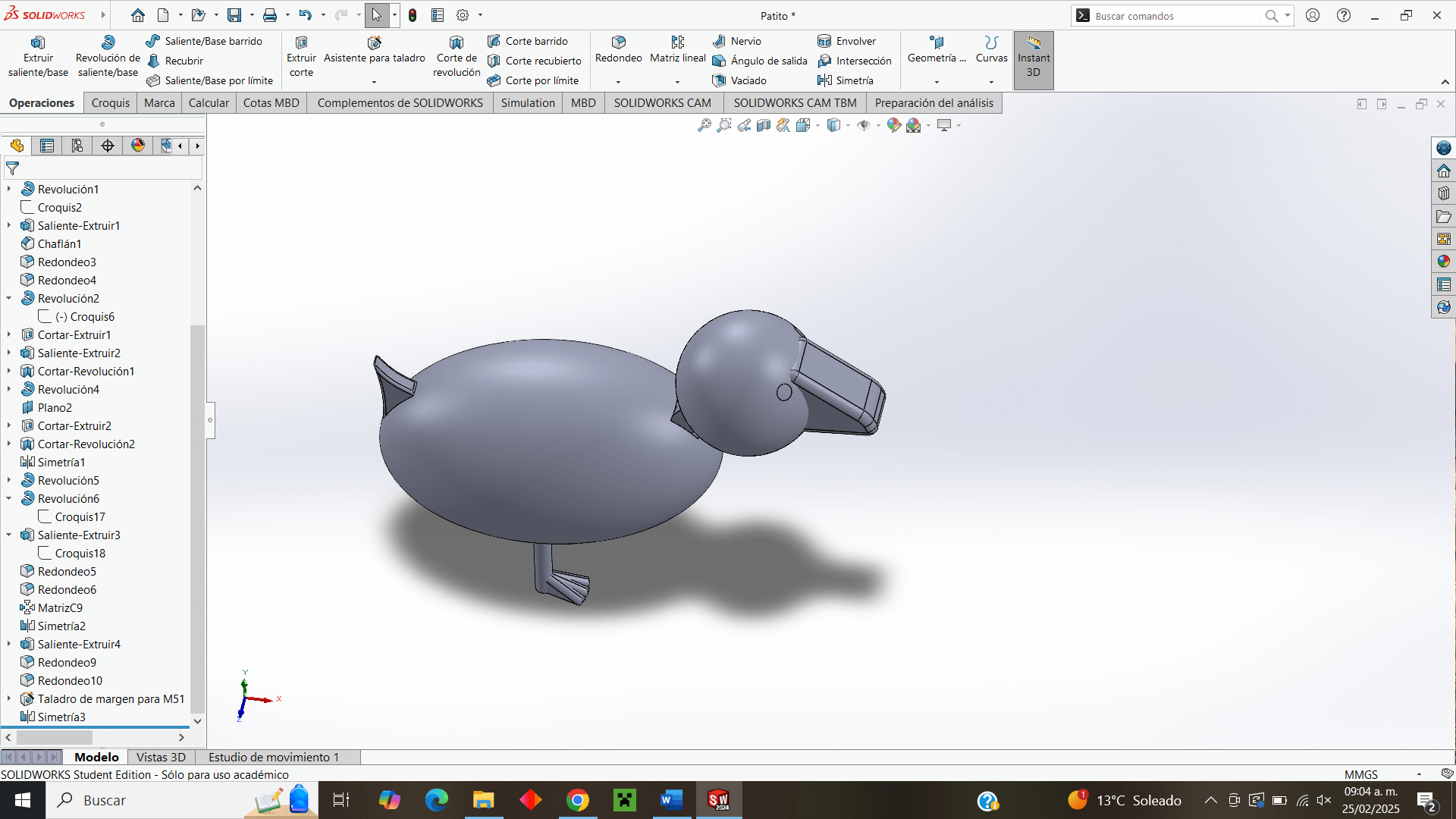
My idea of designing a figure was to make a duck that moved its head to the sides and that its legs were articulated, although in the end I was inclined to design a chick but maintaining the idea of the joints.
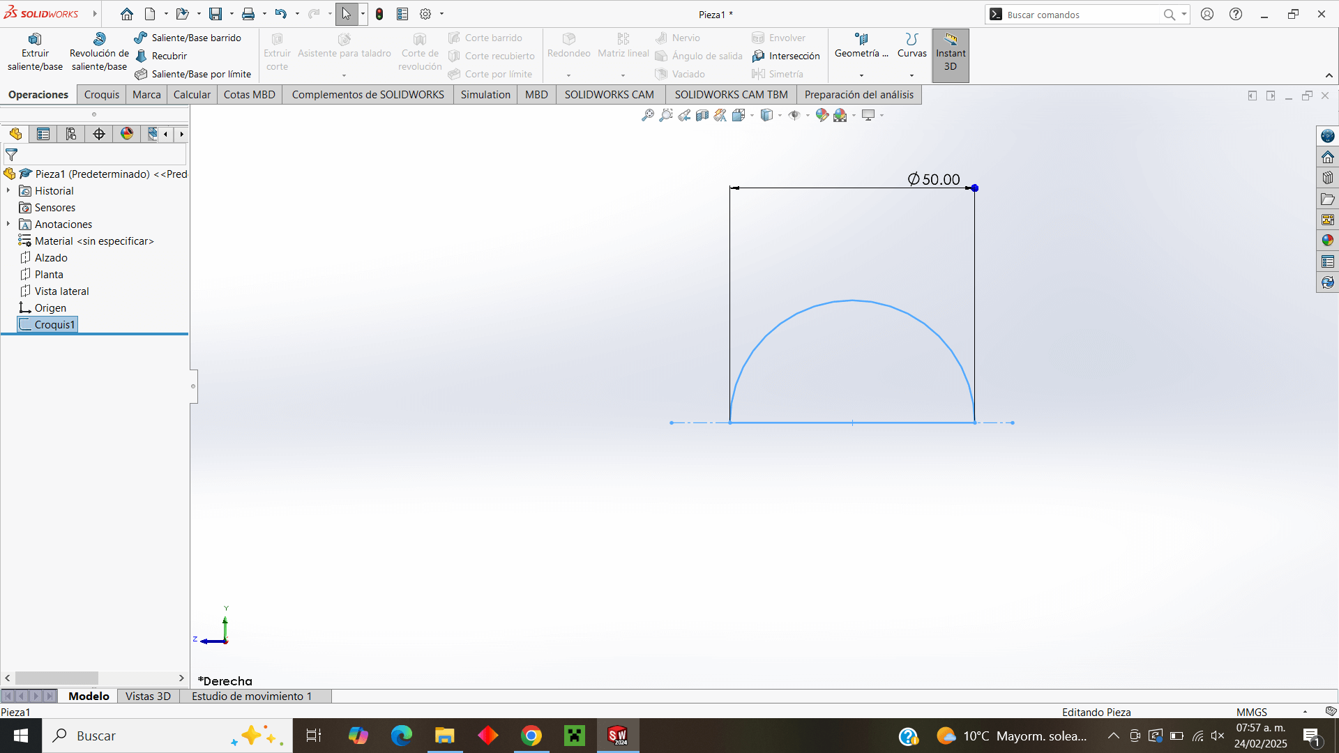
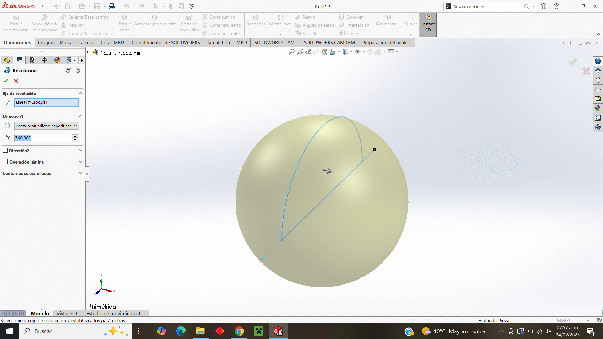
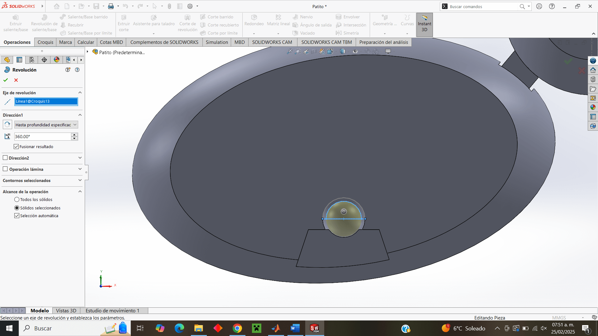
I start by designing a half circle to extrude it with the "Revolution" tool and thus create a sphere.
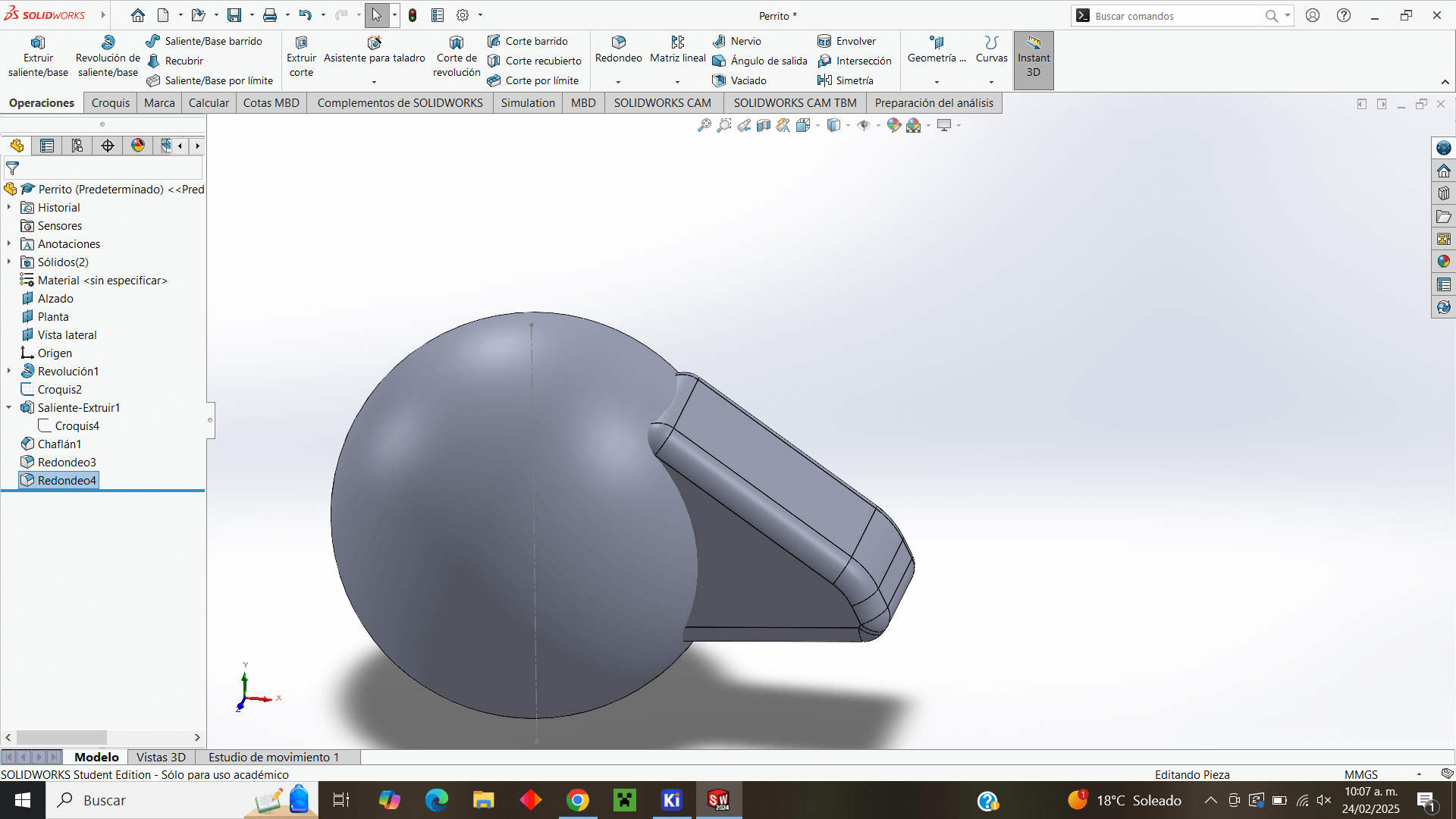
Then, in the elevation plane that is located in the middle of the sphere, I design the "beak" of my figure to extrude it from both sides.
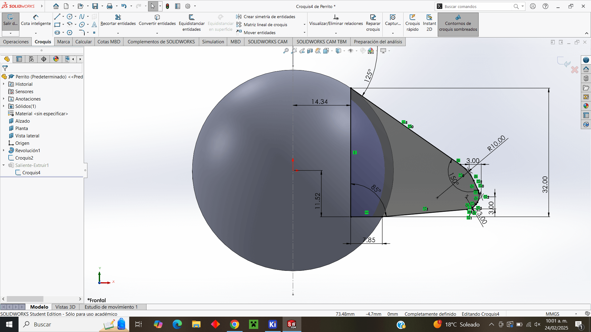
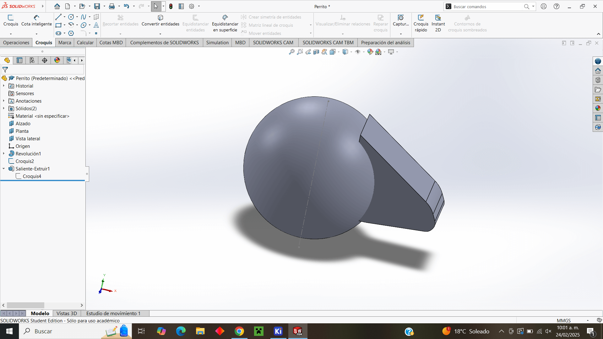
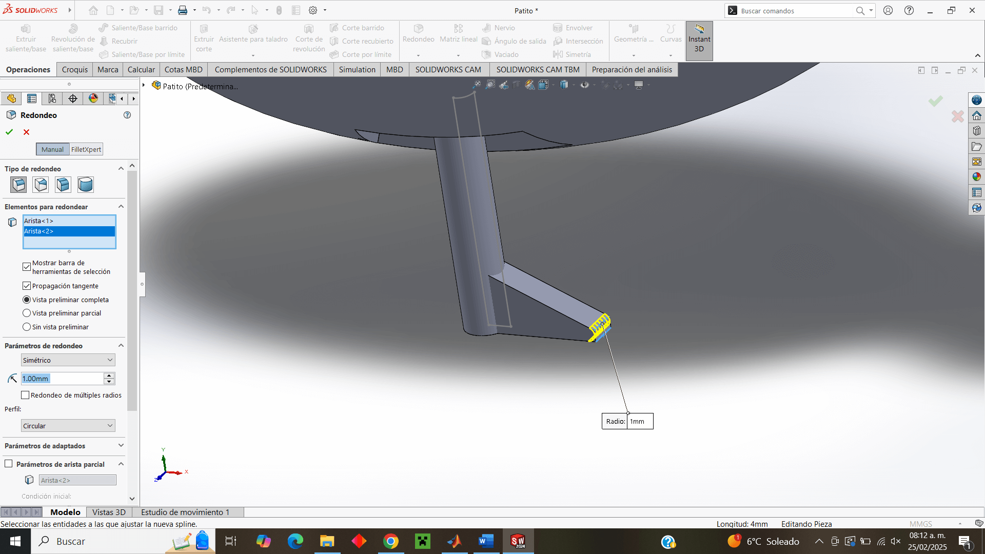
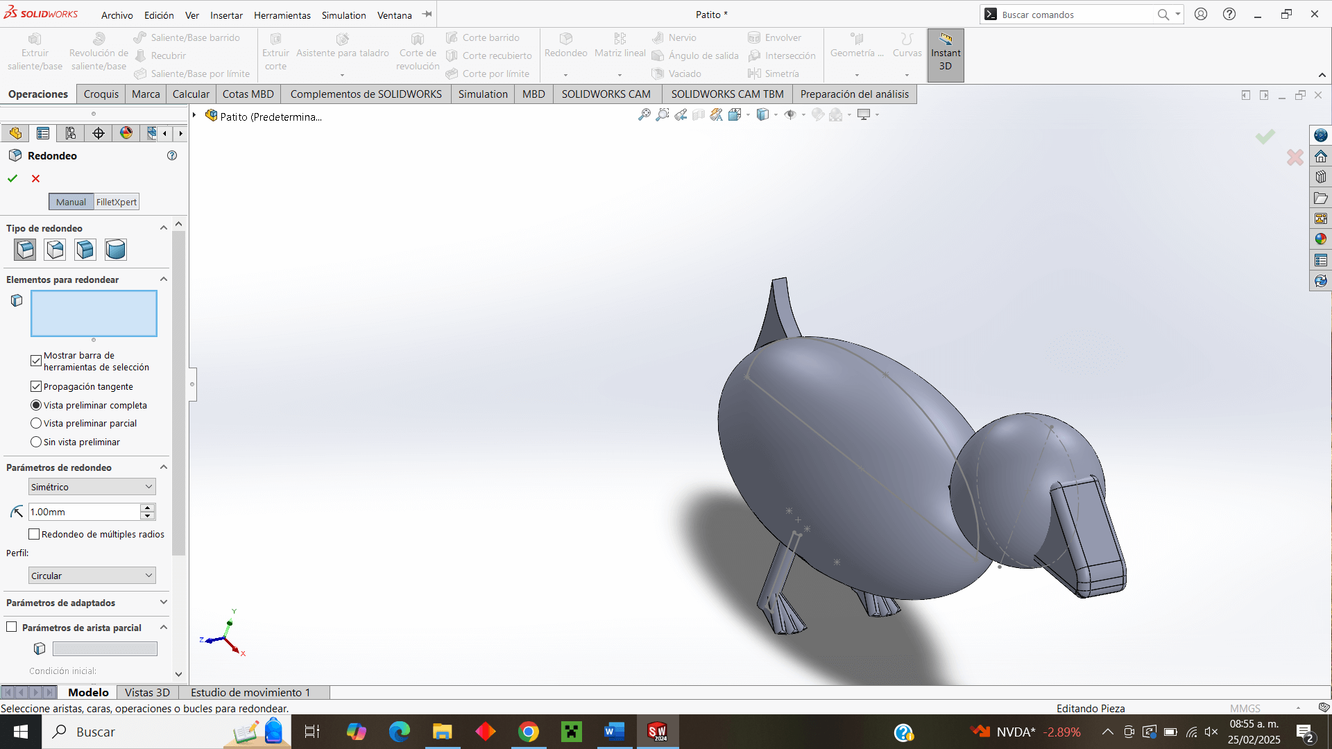
I round the corners for a smoother finish.
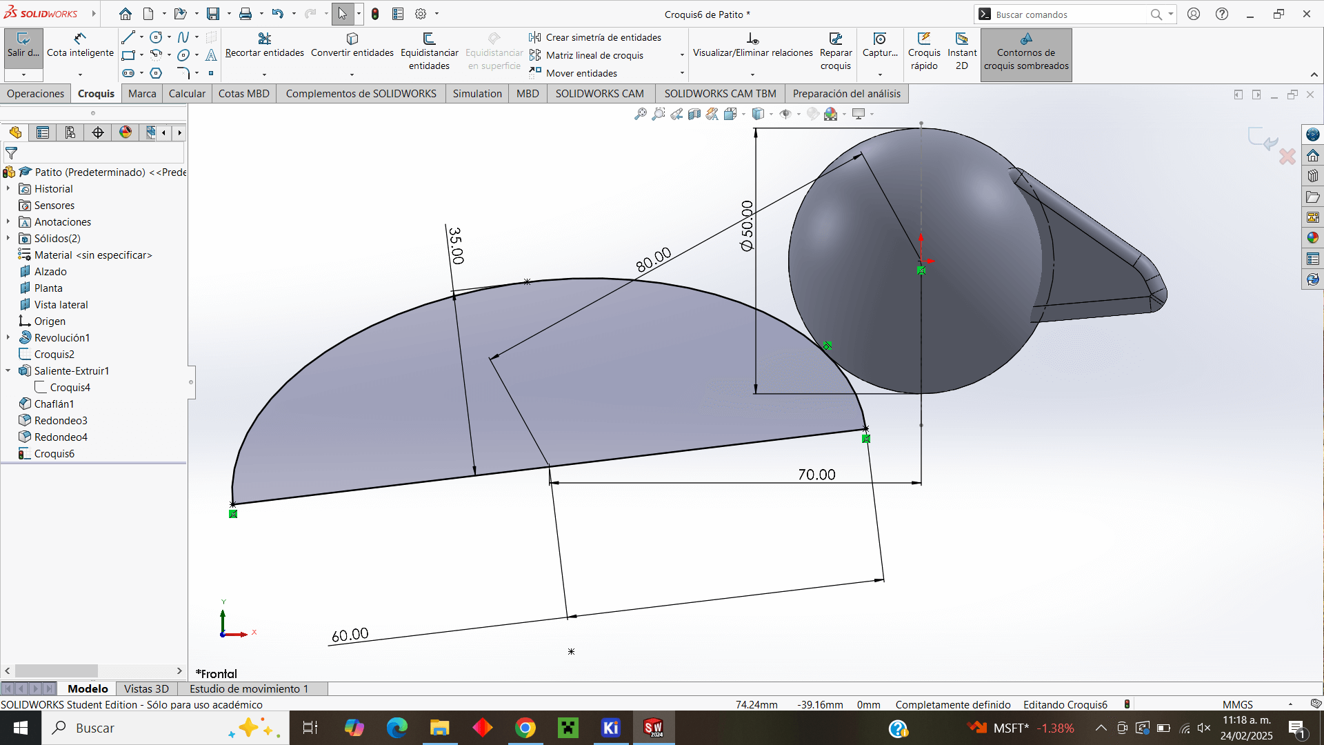
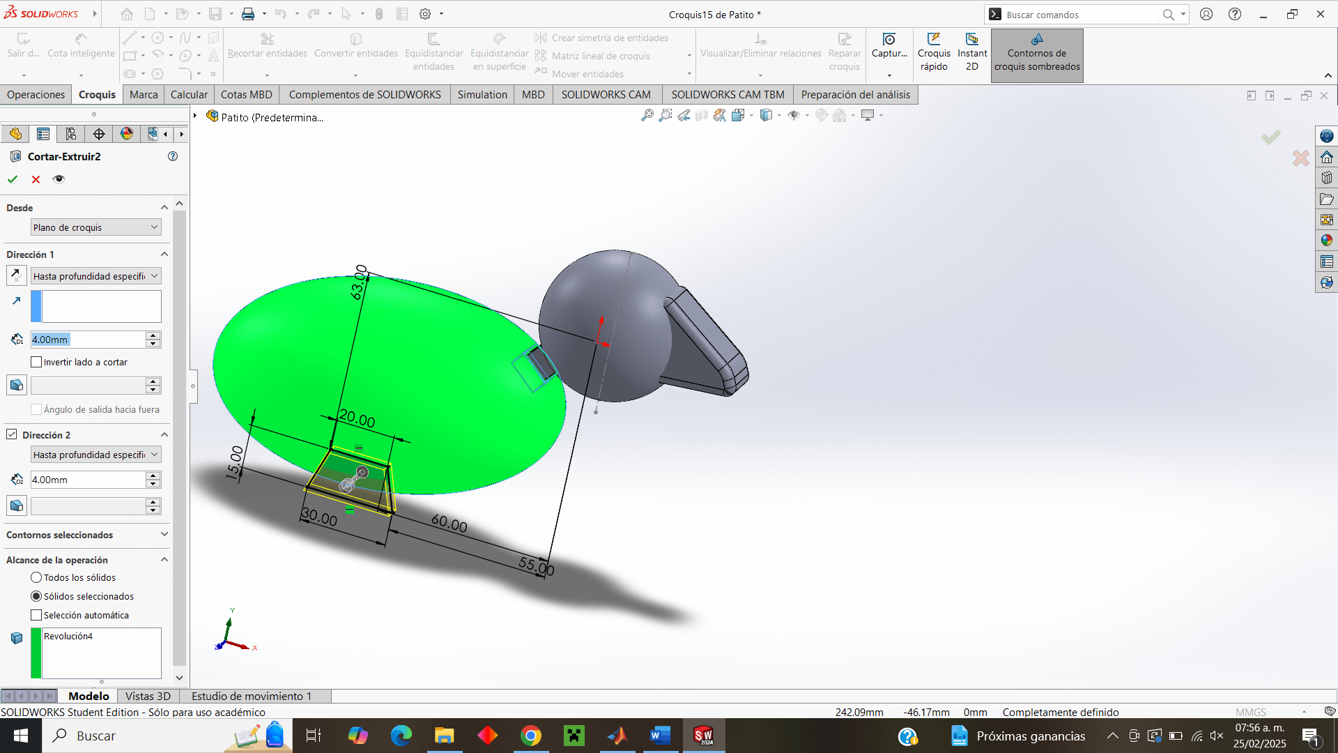
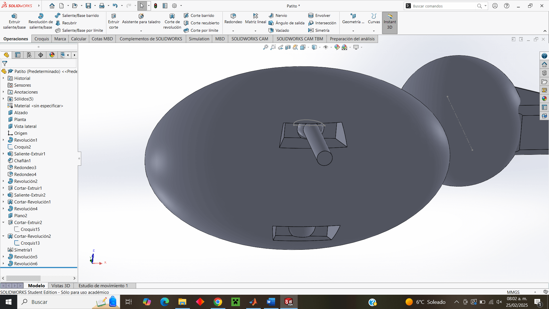
Now, for the body design I draw an ellipse in half, to use the revolution extrusion again.
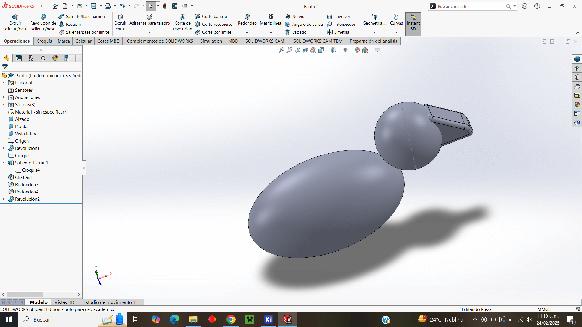
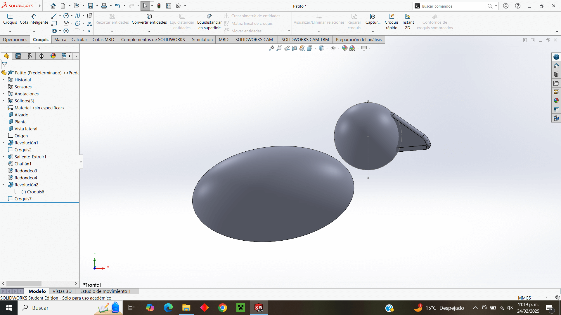
I decided to move the body a little further away from the head in order to be able to make the neck.
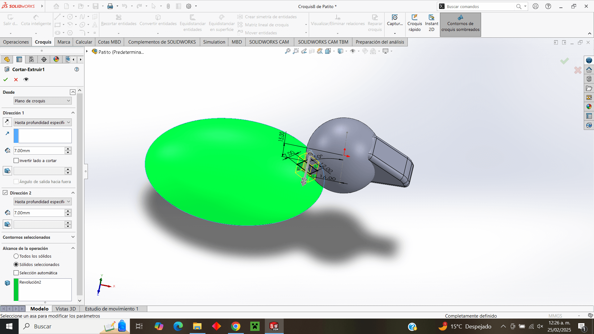
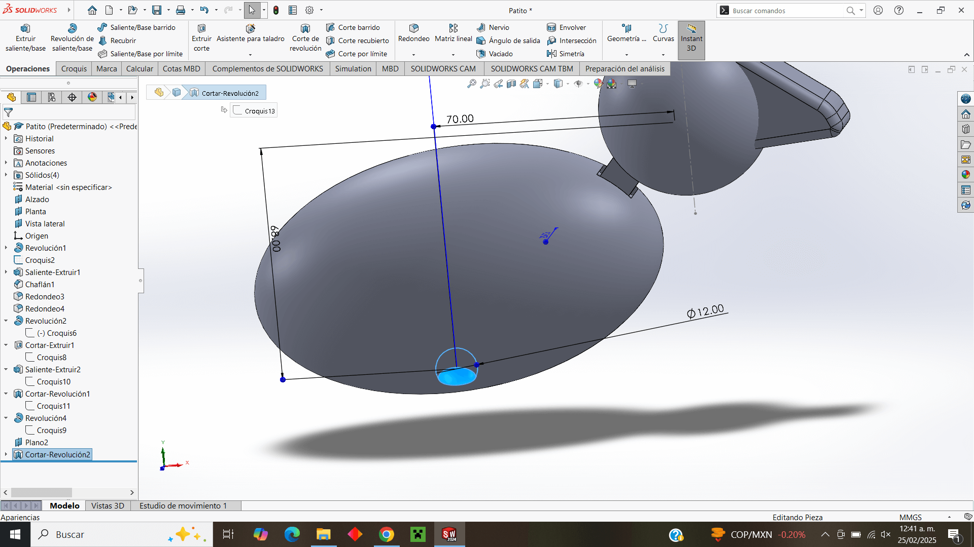
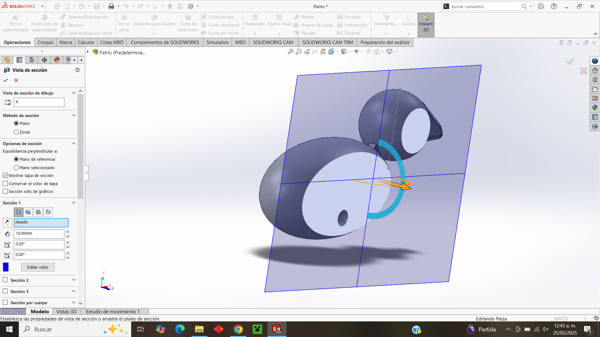
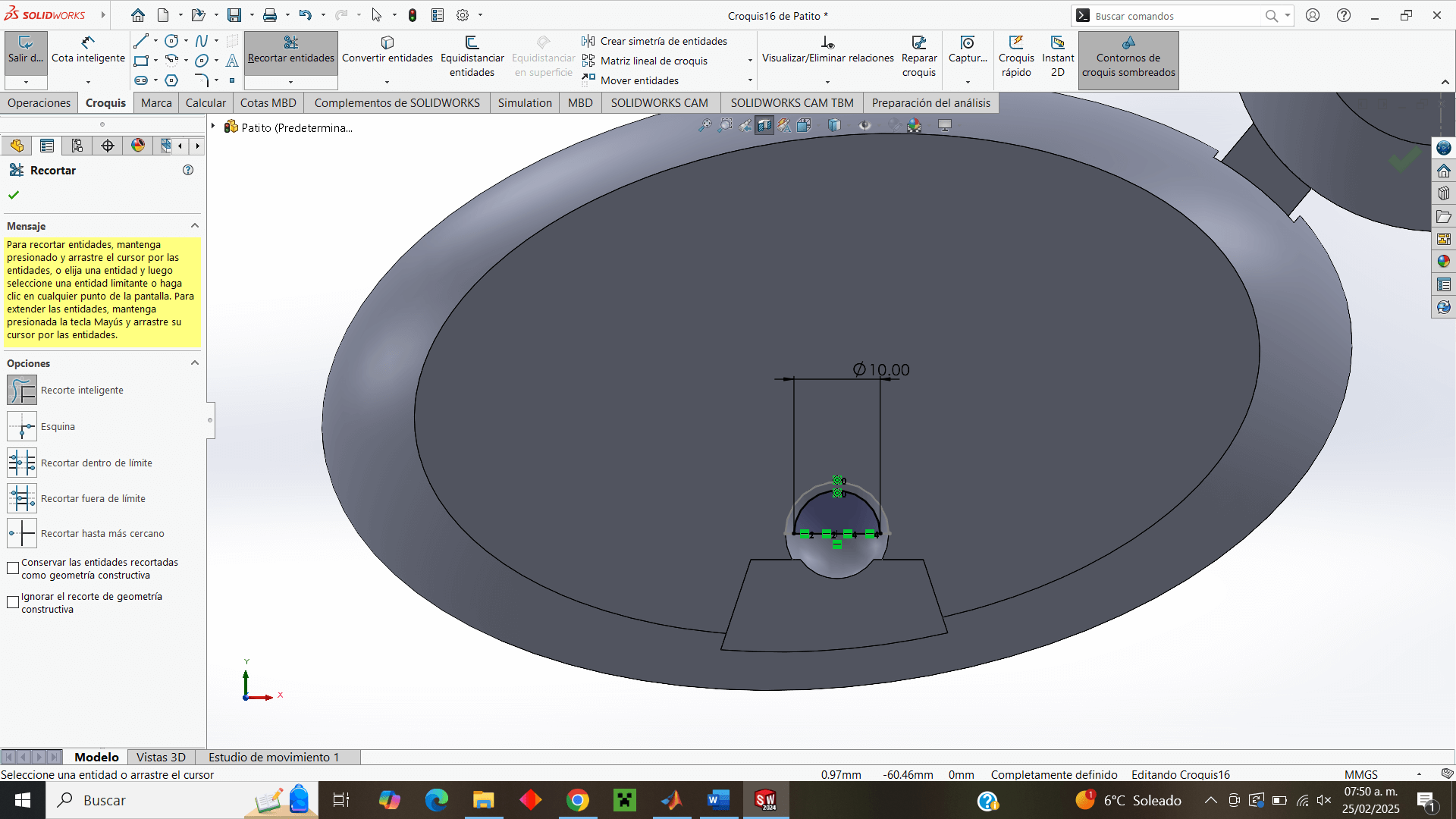
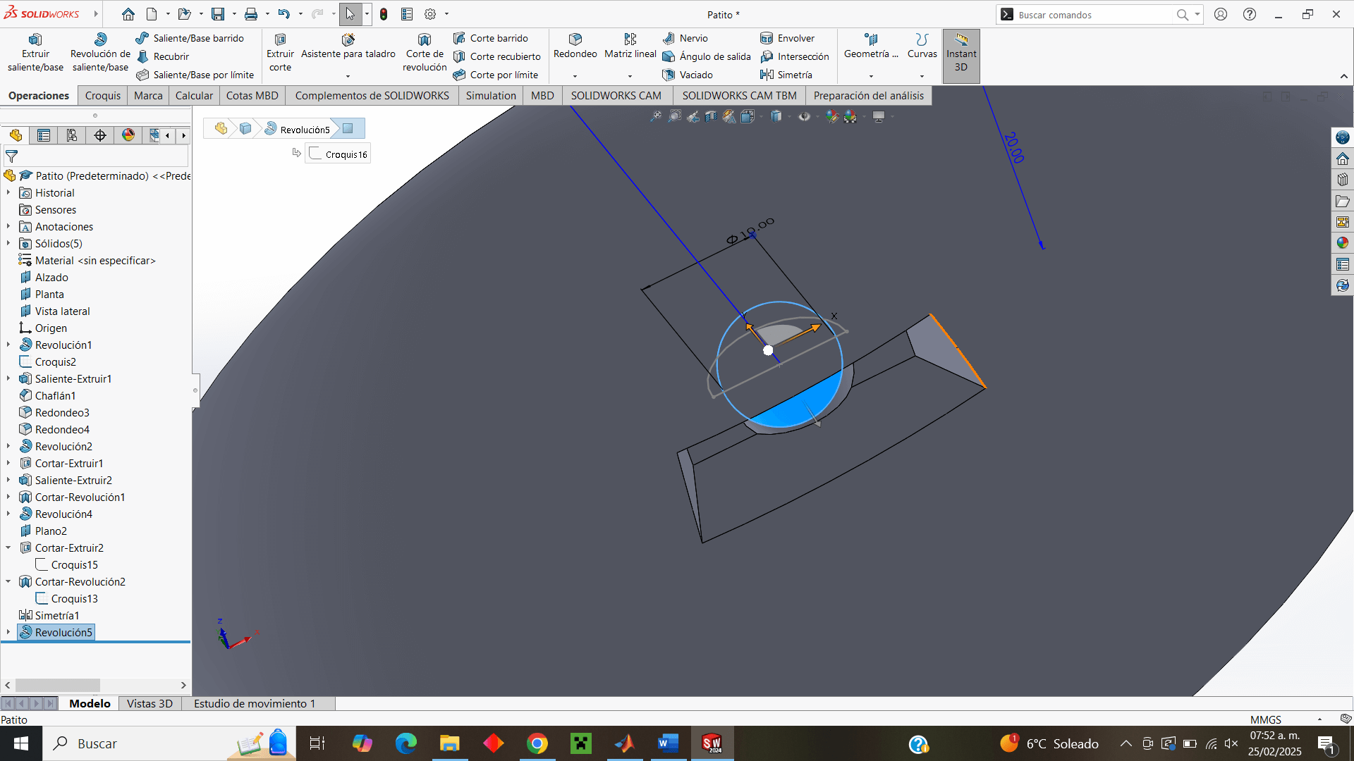
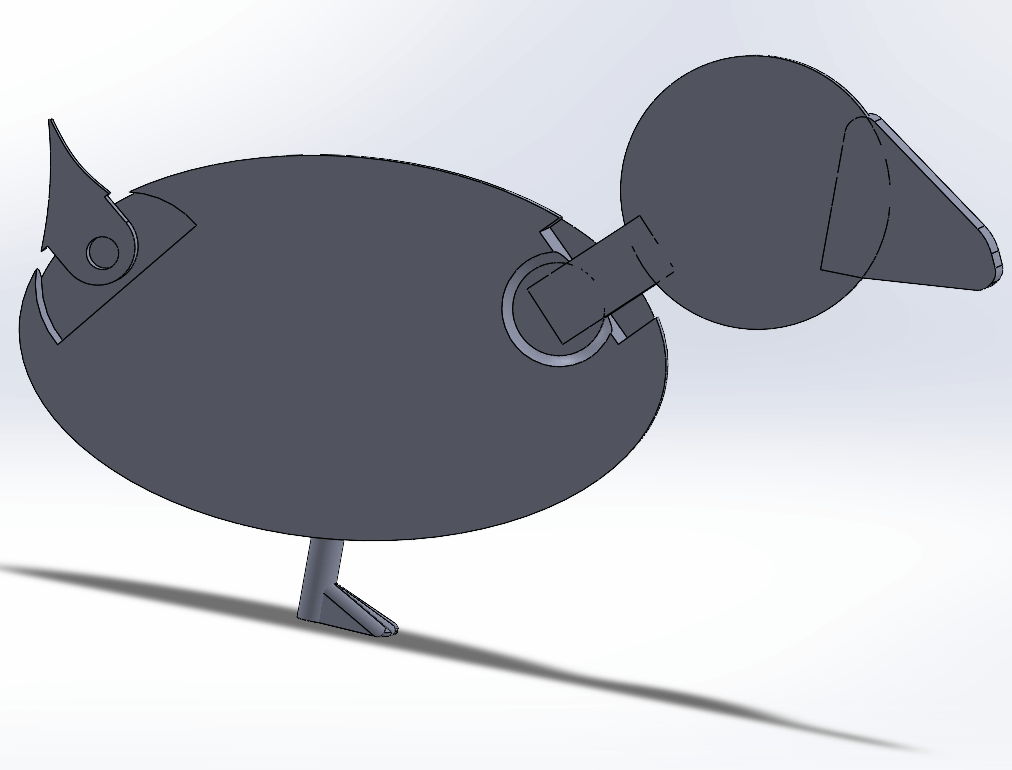
I use the cutaway view to see only half of the piece, and on the same plane I work and make the neck joint, which in a simple way can be seen as a ring that is crossed by a cylinder.
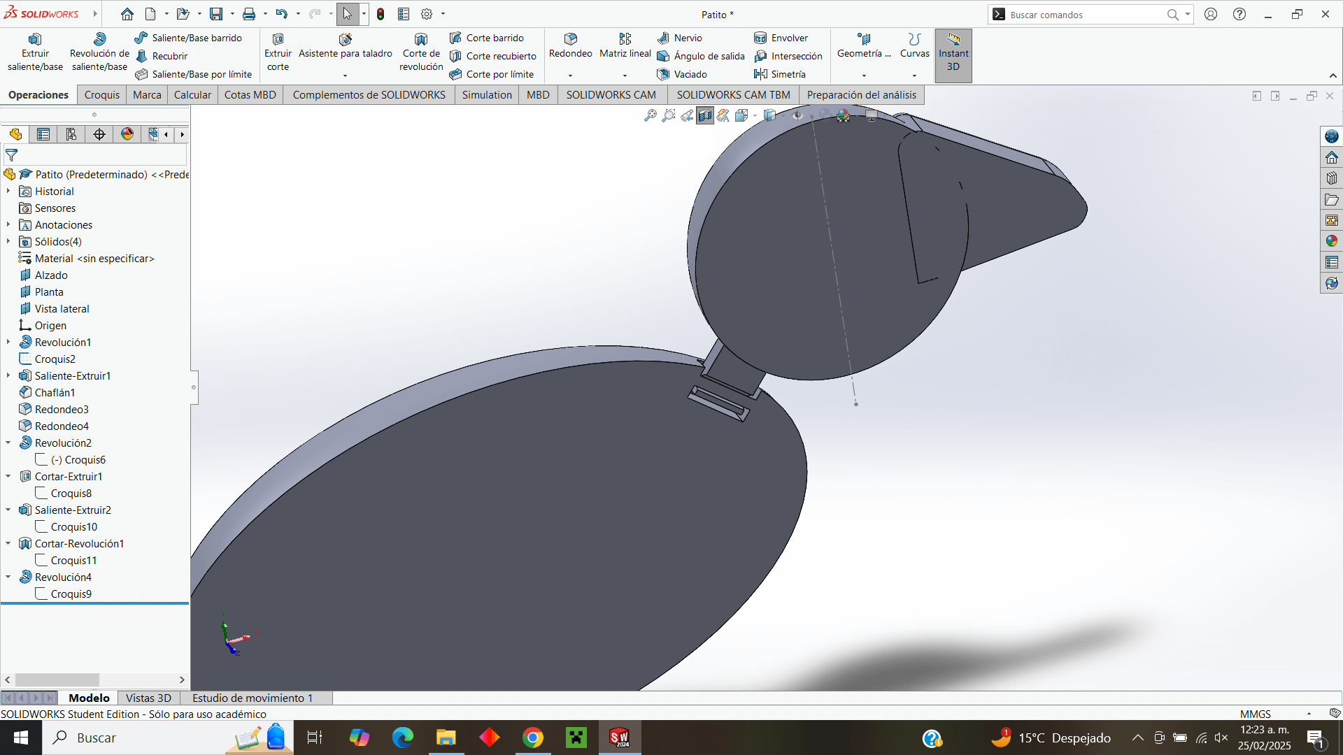
I make the cut so that the "ring" has enough room to move to the sides
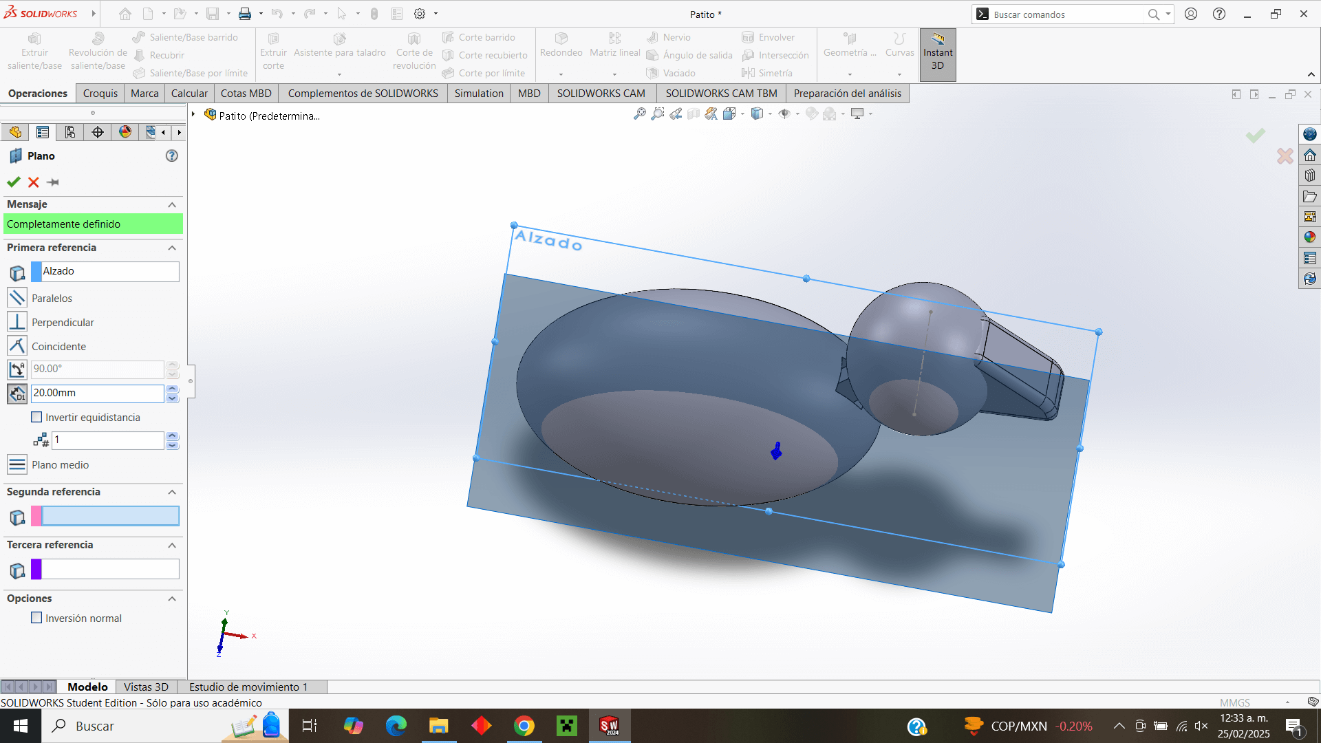
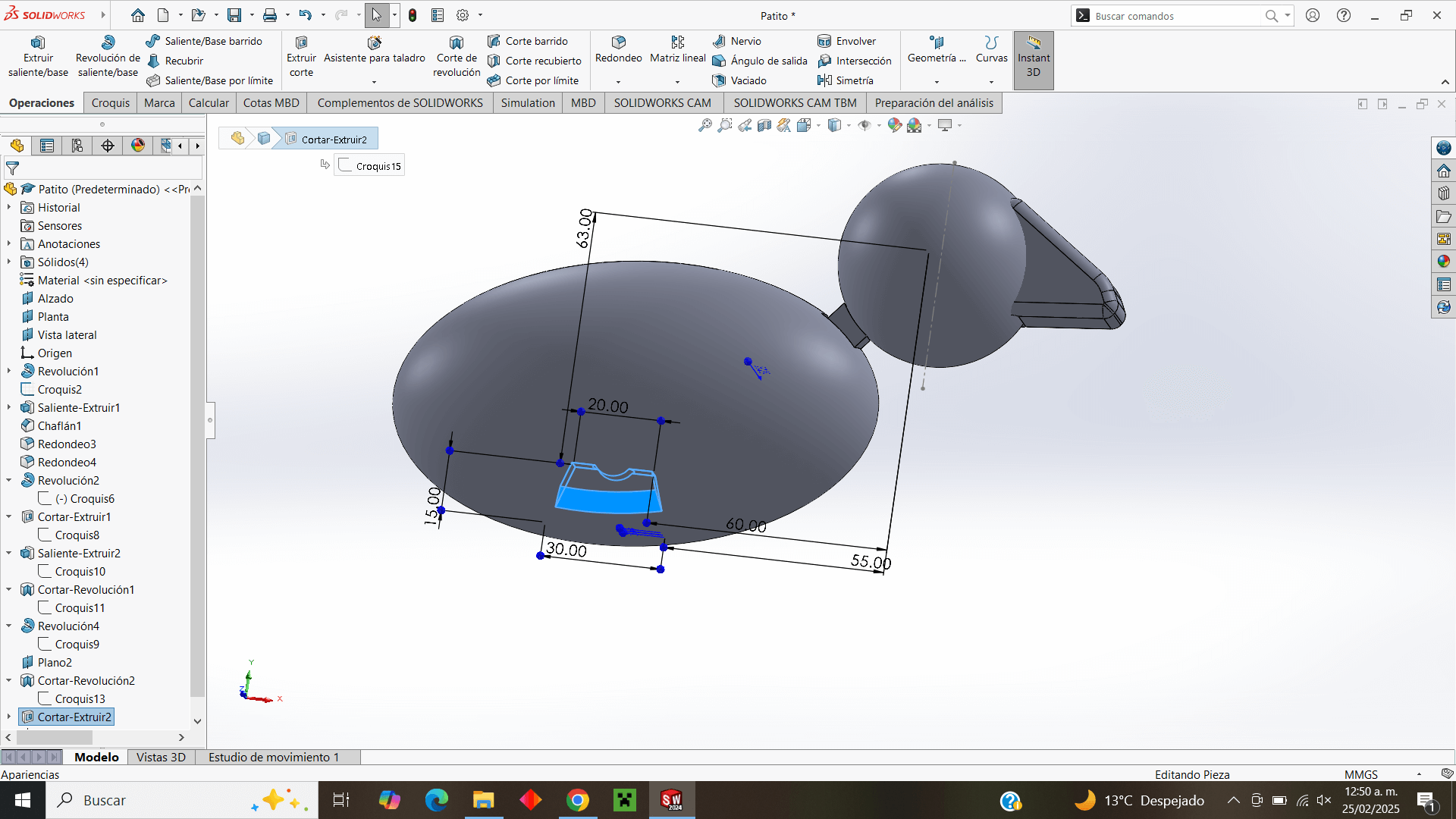
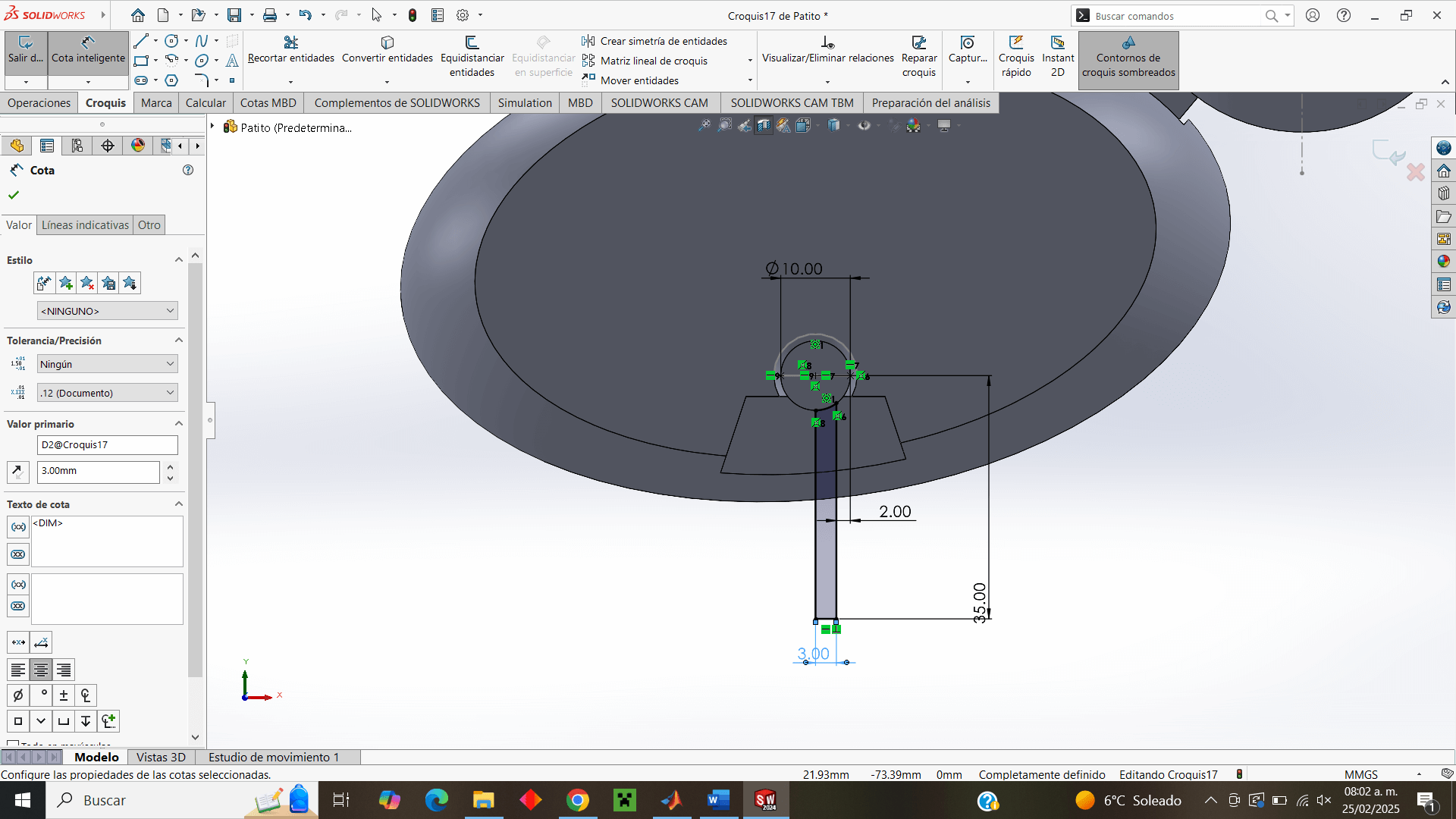
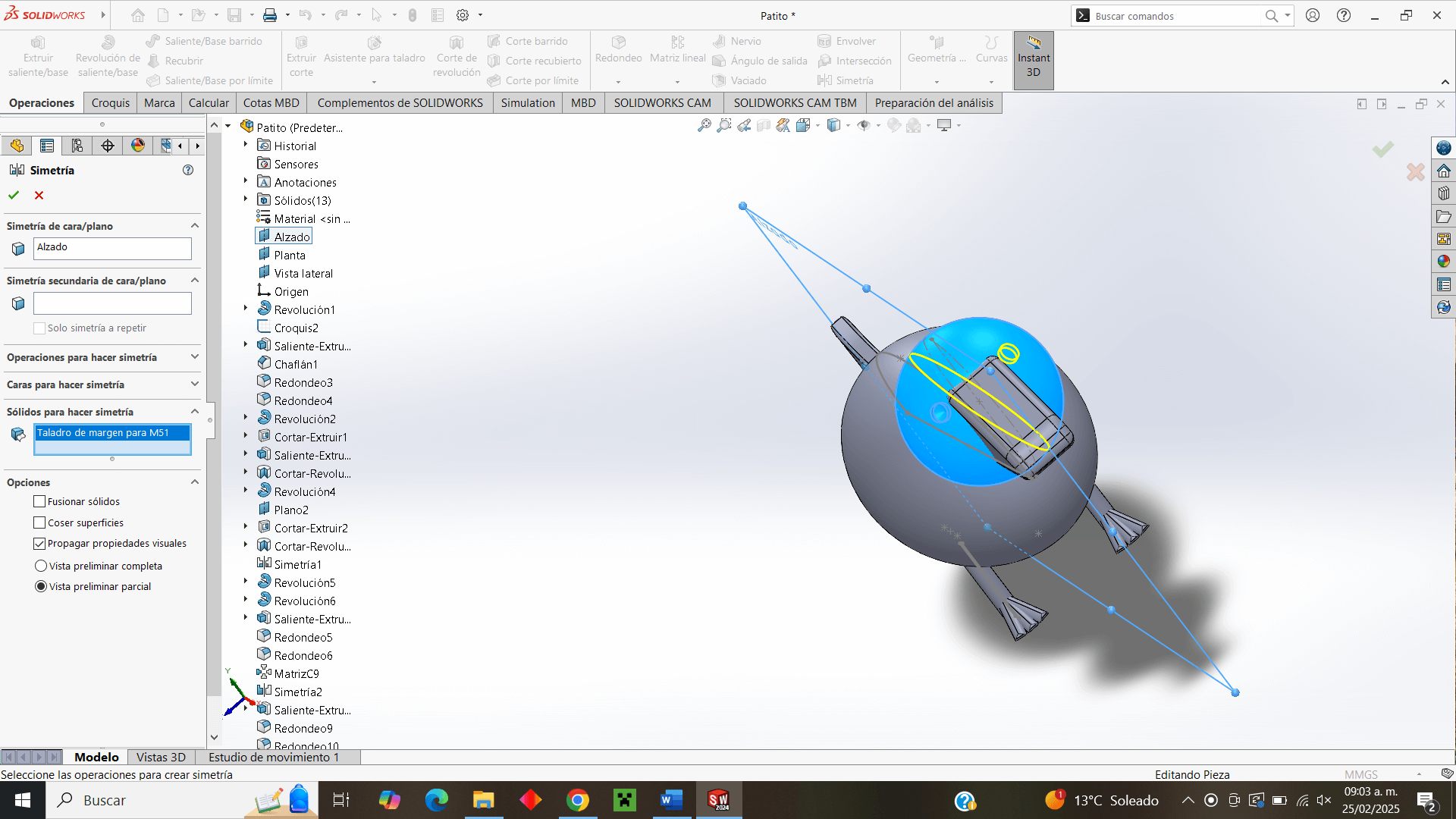
Now I place a plane 20 mm from the elevation plane, in order to design the duck's legs, which are obviously far from the center of the piece.
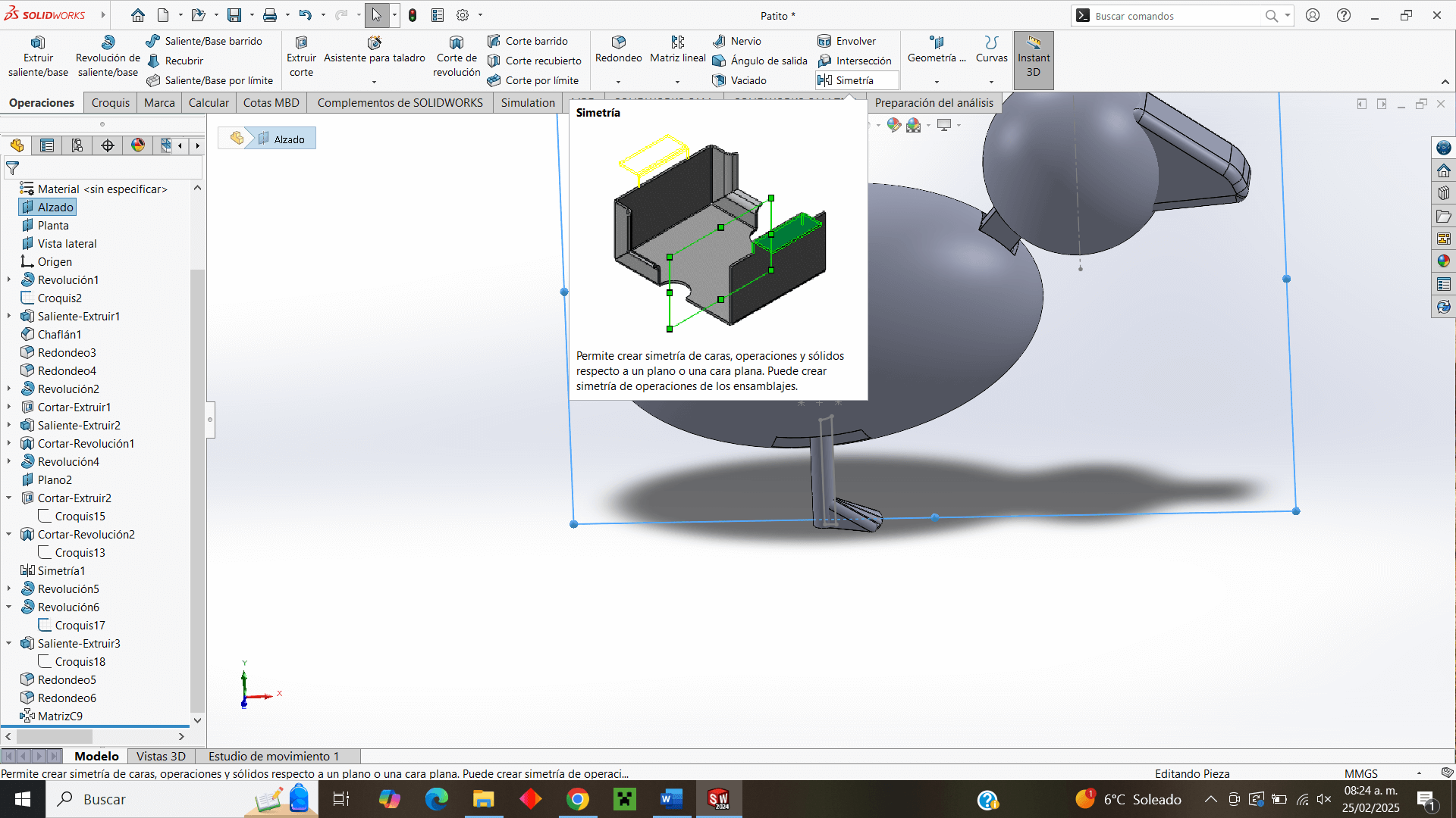
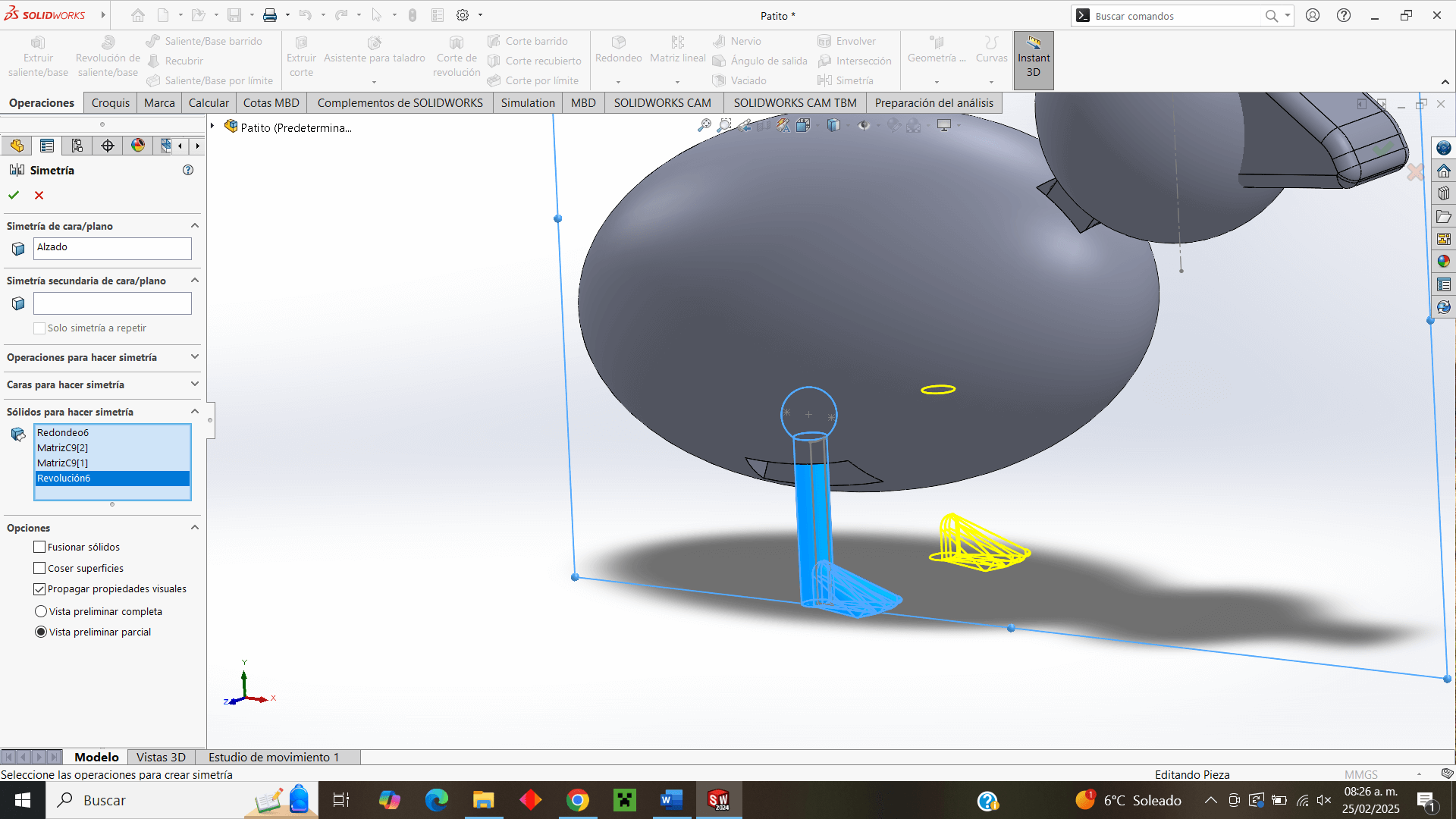
Once the plan is done, I work on it and make the holes where the leg joint will go to later make a symmetry and have the holes for the two legs.
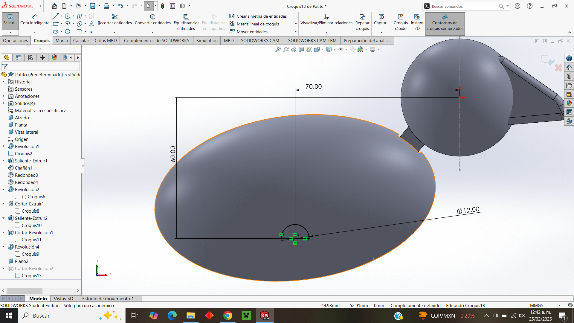
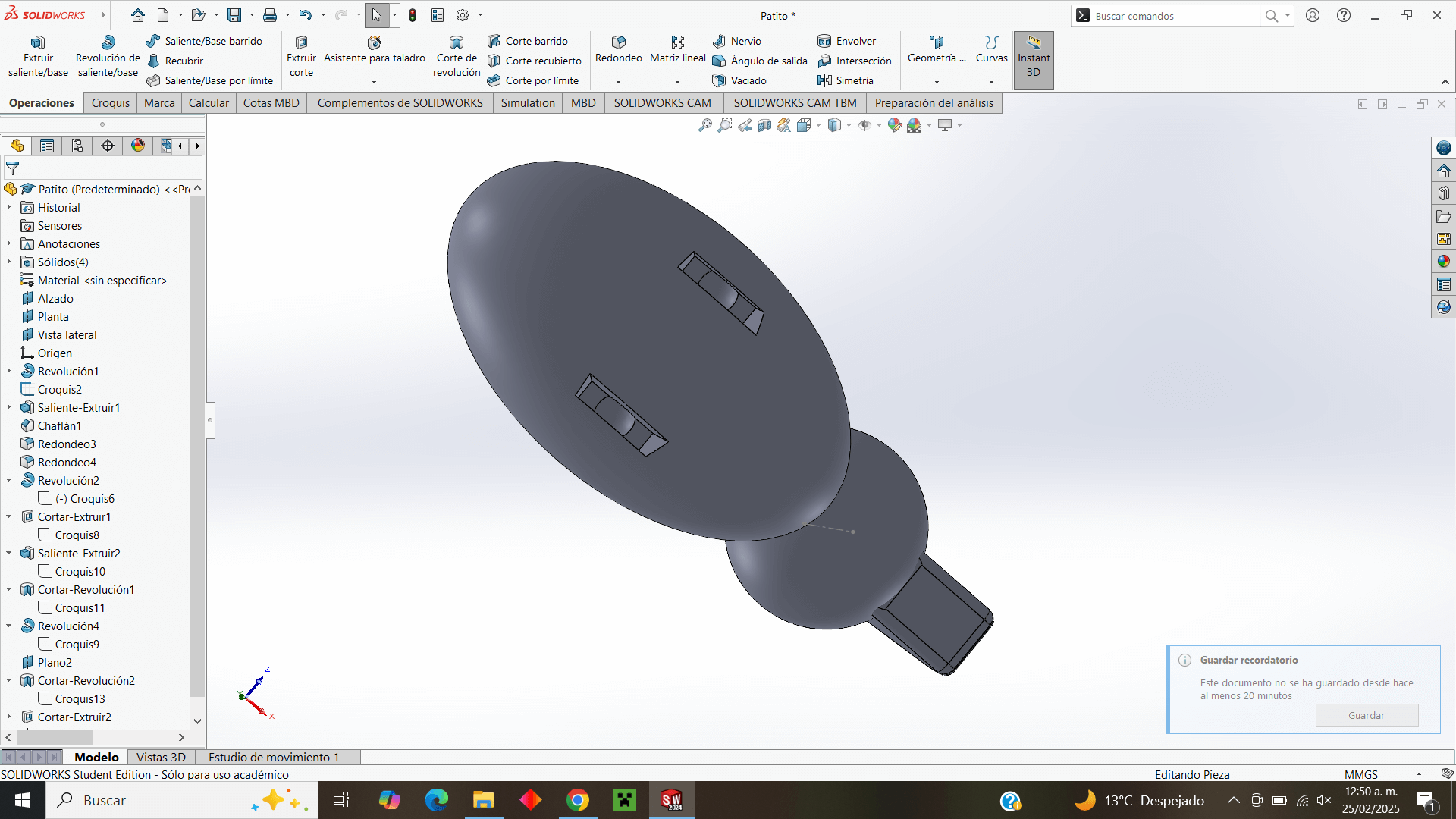
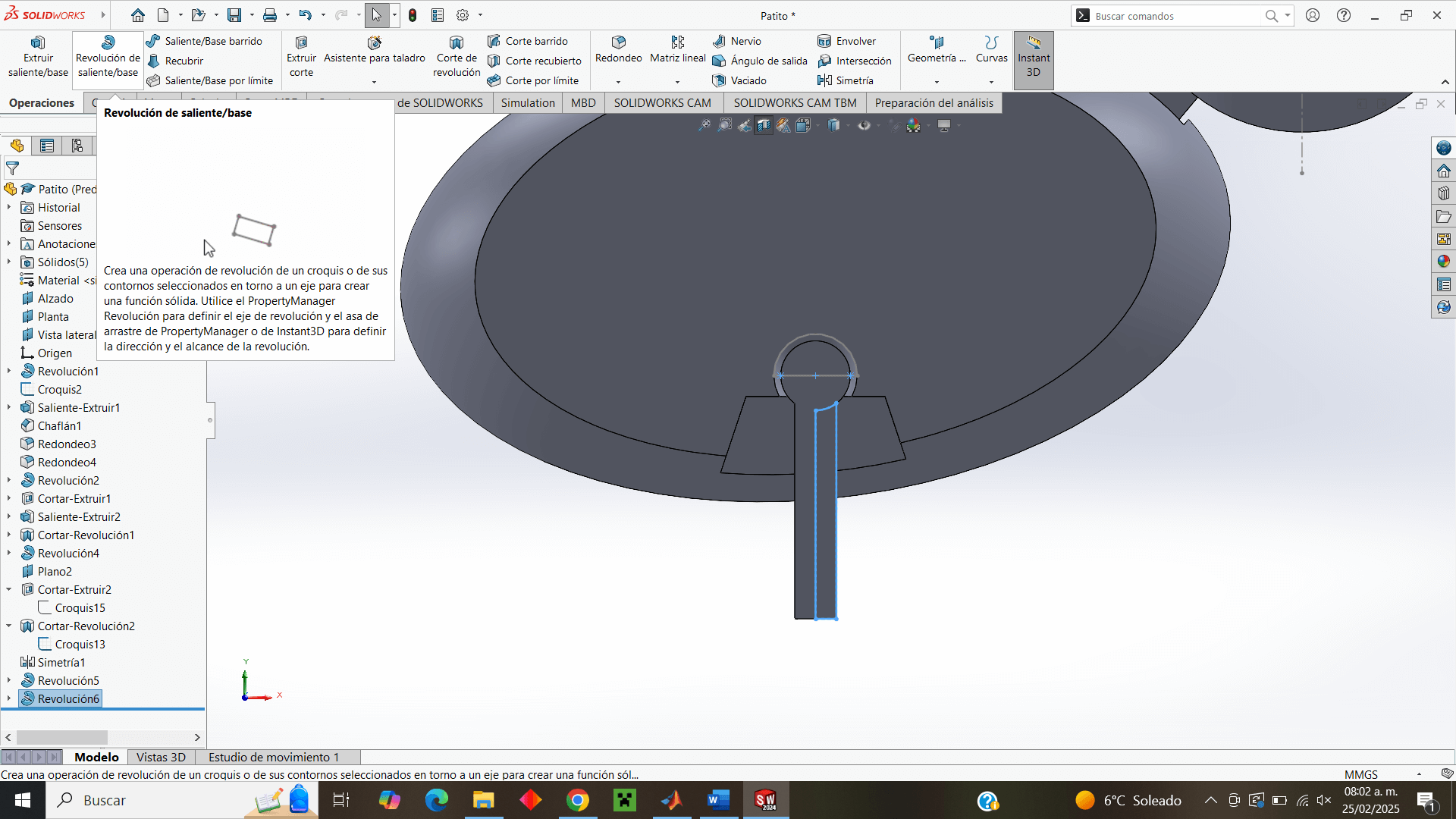
Now, similar to the previous procedure, I make the joint in that plane with the difference that it will not be a cut but an extrusion and I make the complete leg to make a symmetry again.
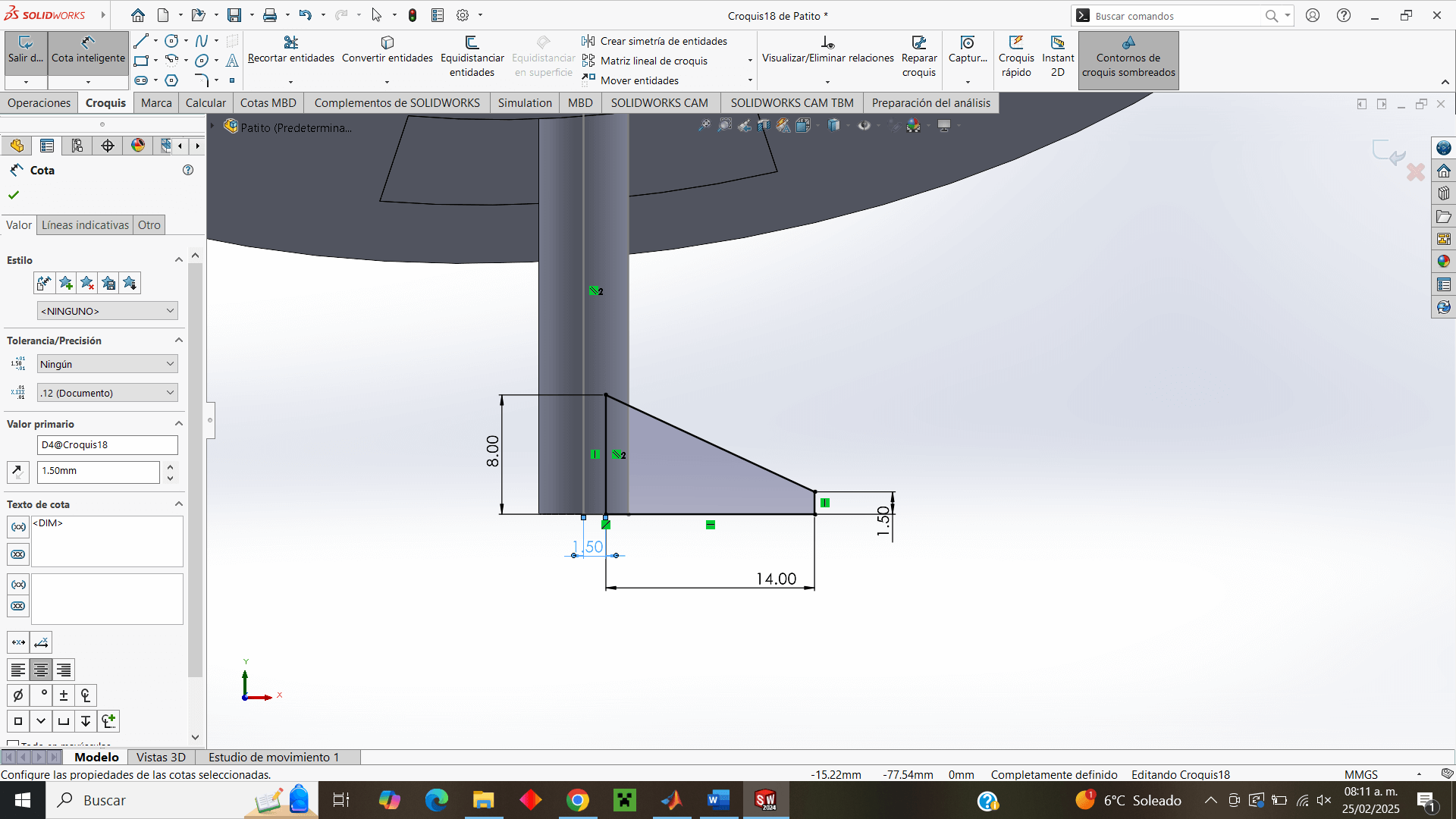
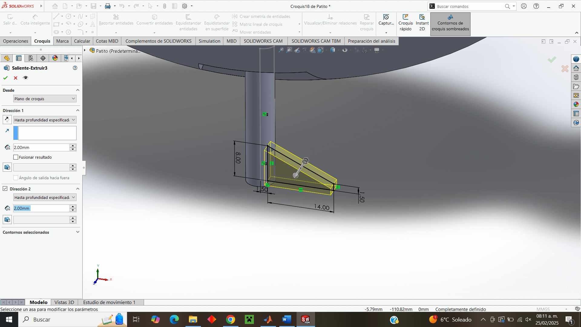
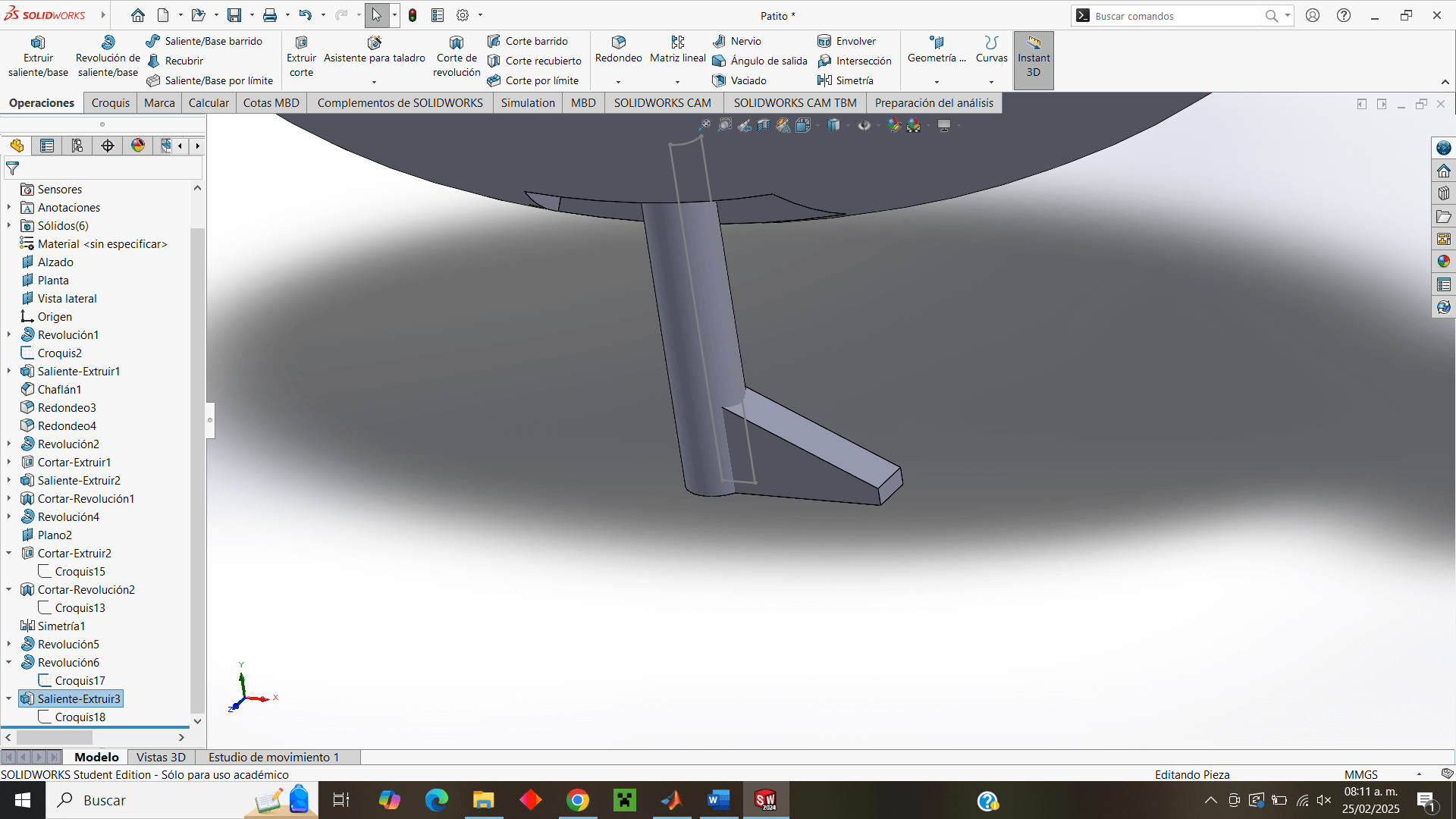
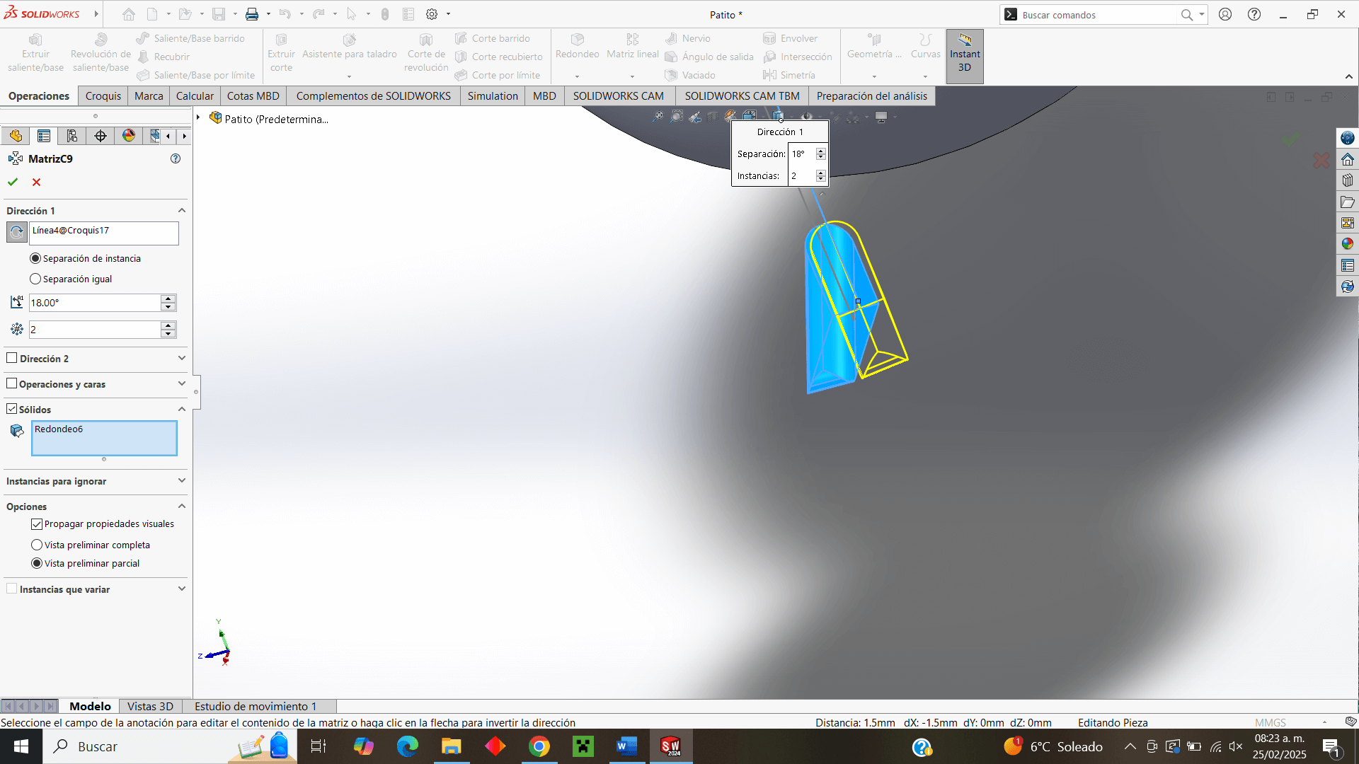
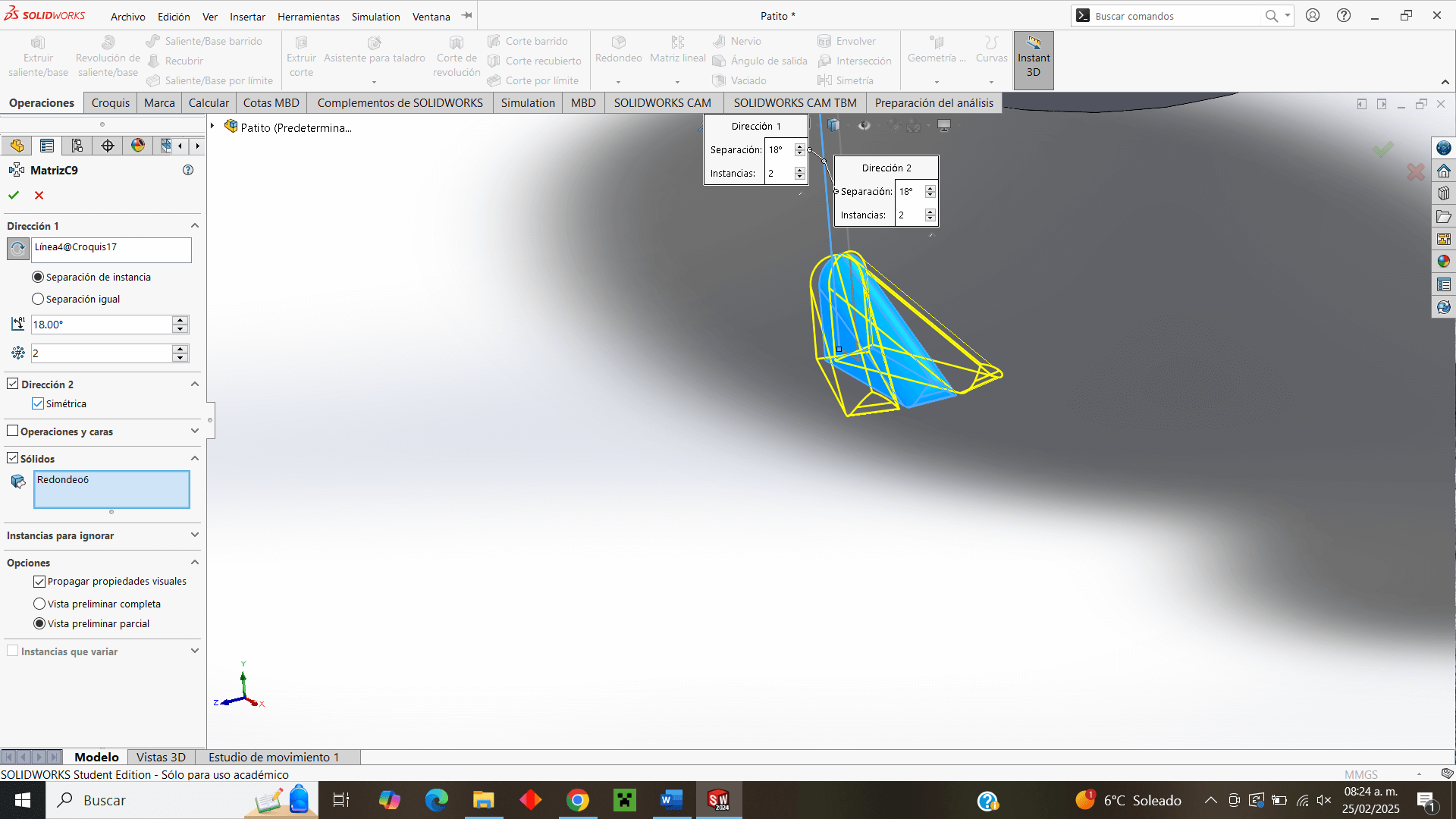
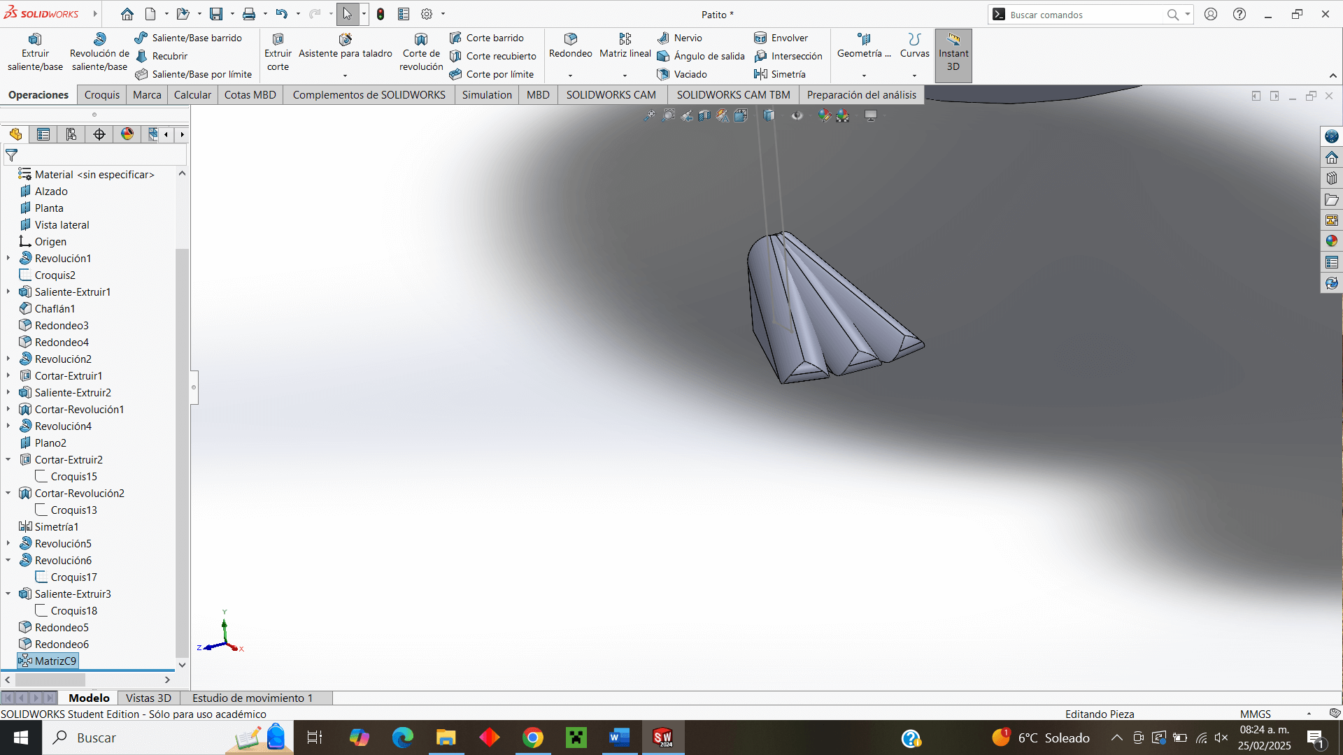
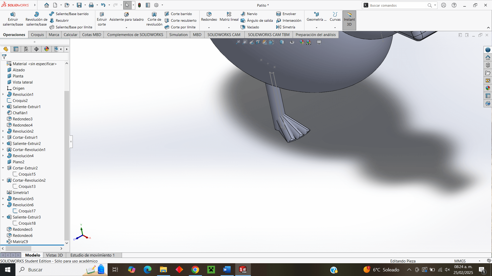
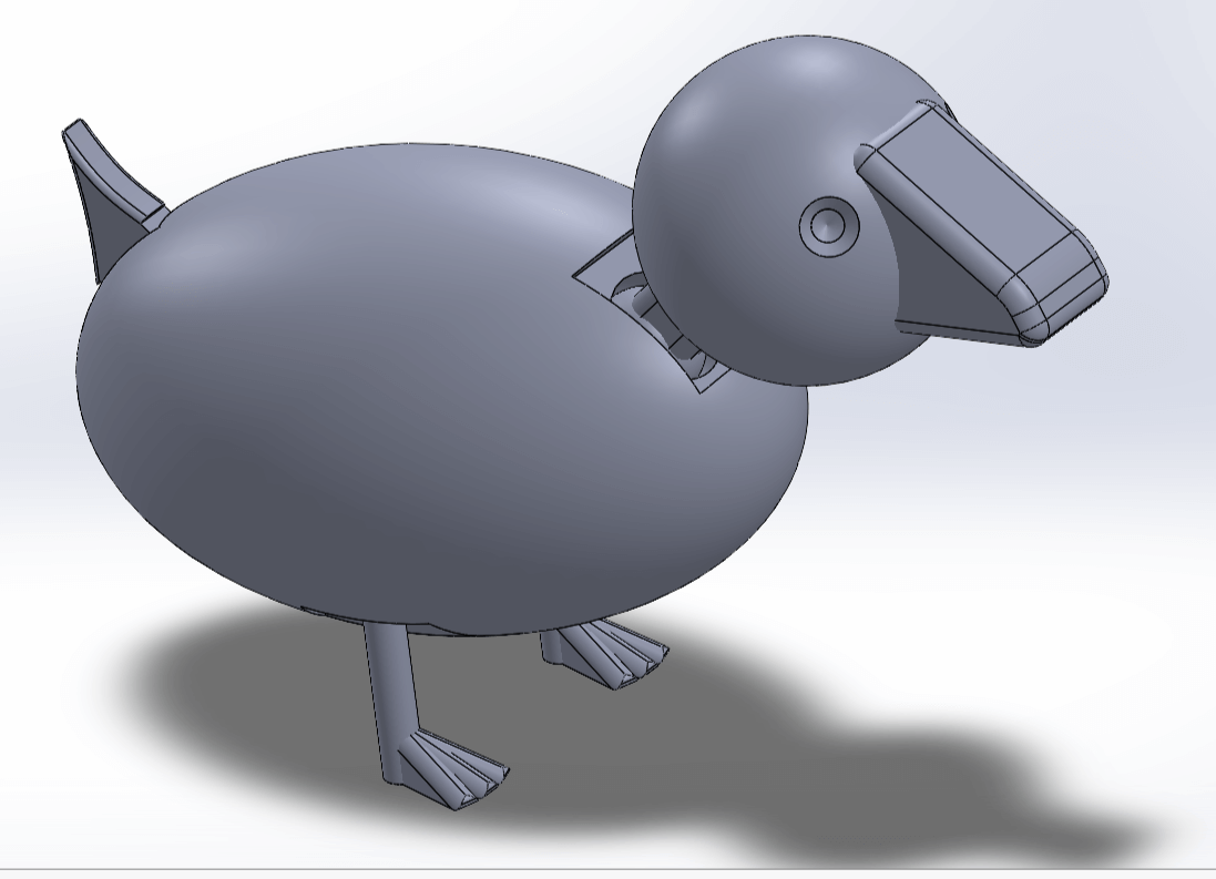
A special operation I decided to do was with the foot of the leg, to simulate the "triangular" legs that ducks have, making use of the "Matrix" operation, adding two extra pieces with an angle separation to give that characteristic shape of the ducks' palms.
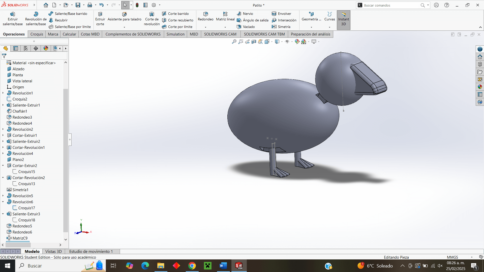
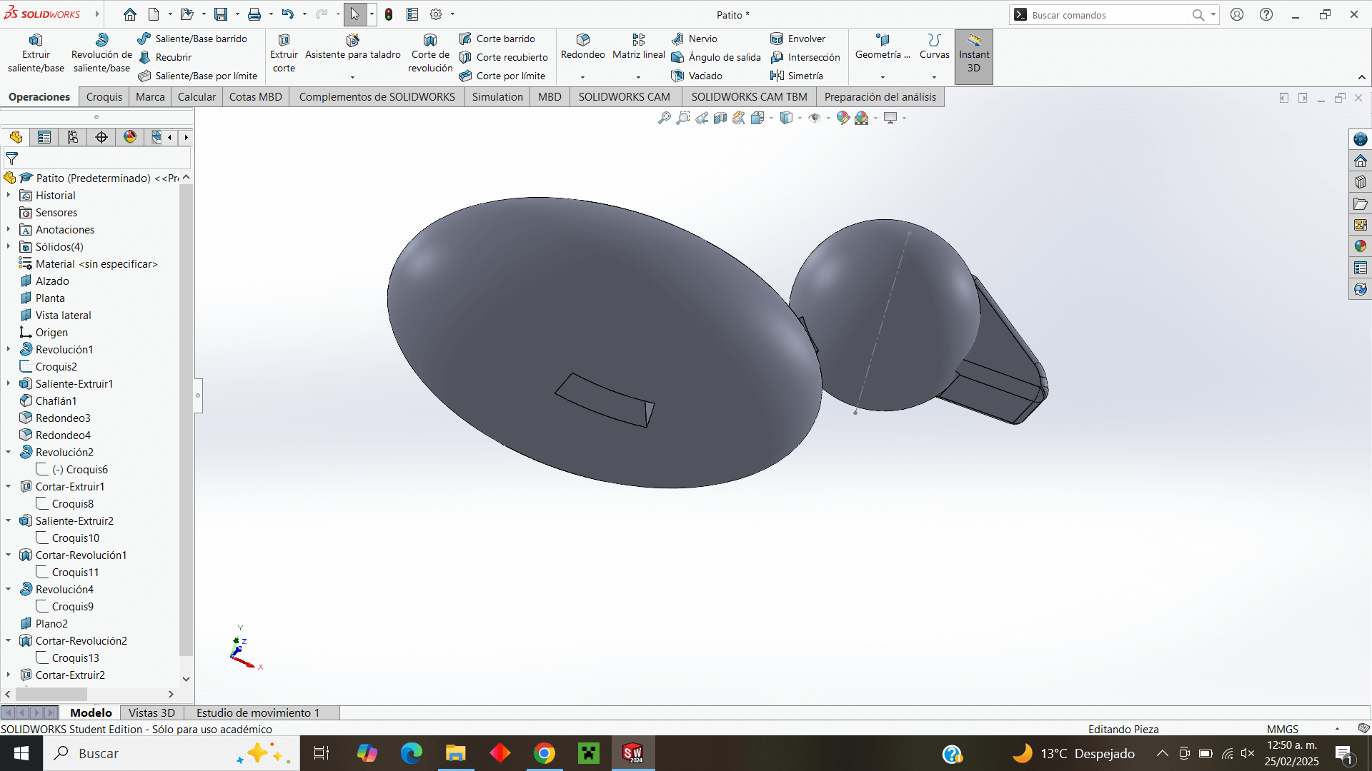
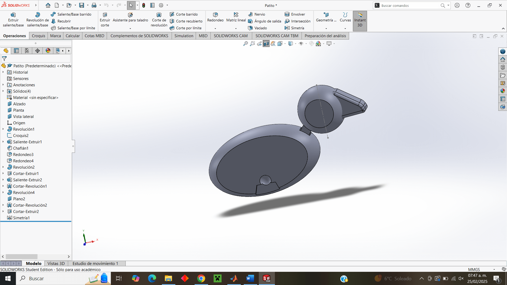
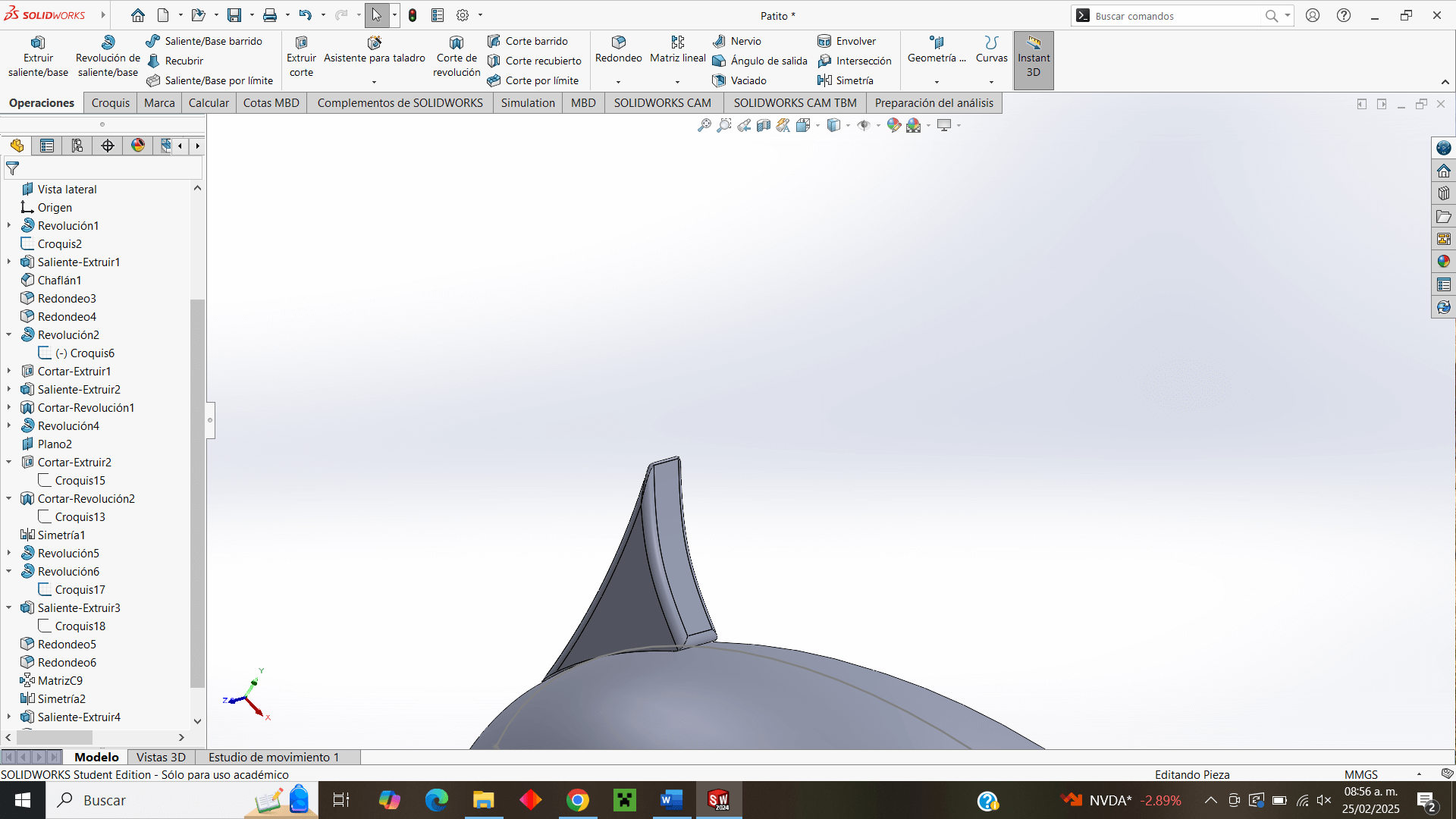
Almost lastly, I make the duck's tail to give a more "correct" detail to the body of a duck.
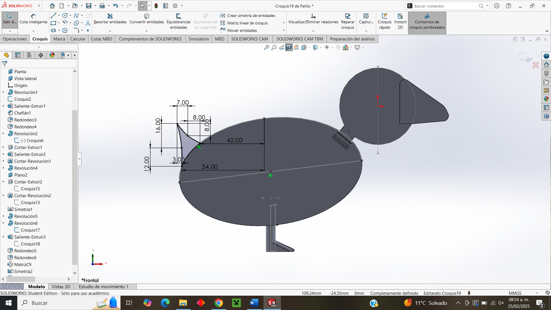
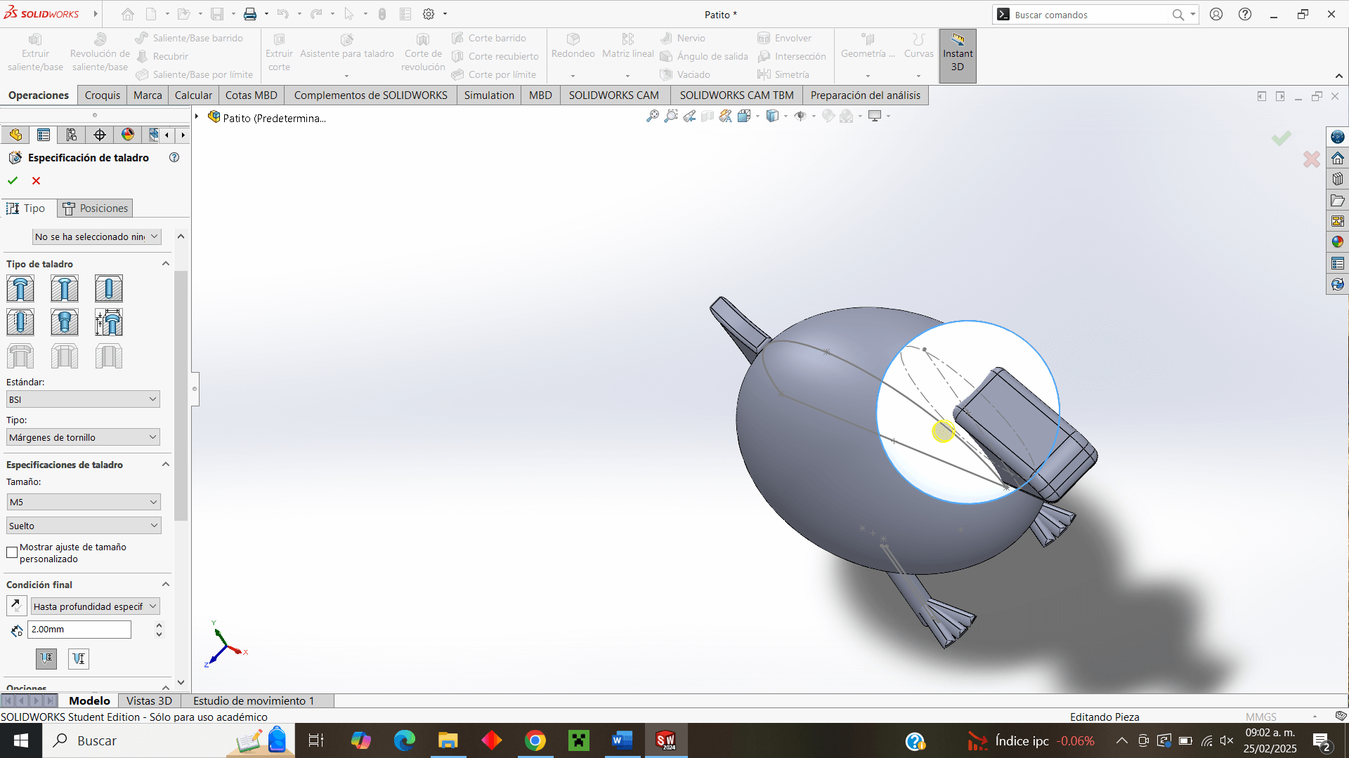
Finally, in the design, I use the "drill specification" operation to make the eyes and give the design a little extra detail.
3d printing
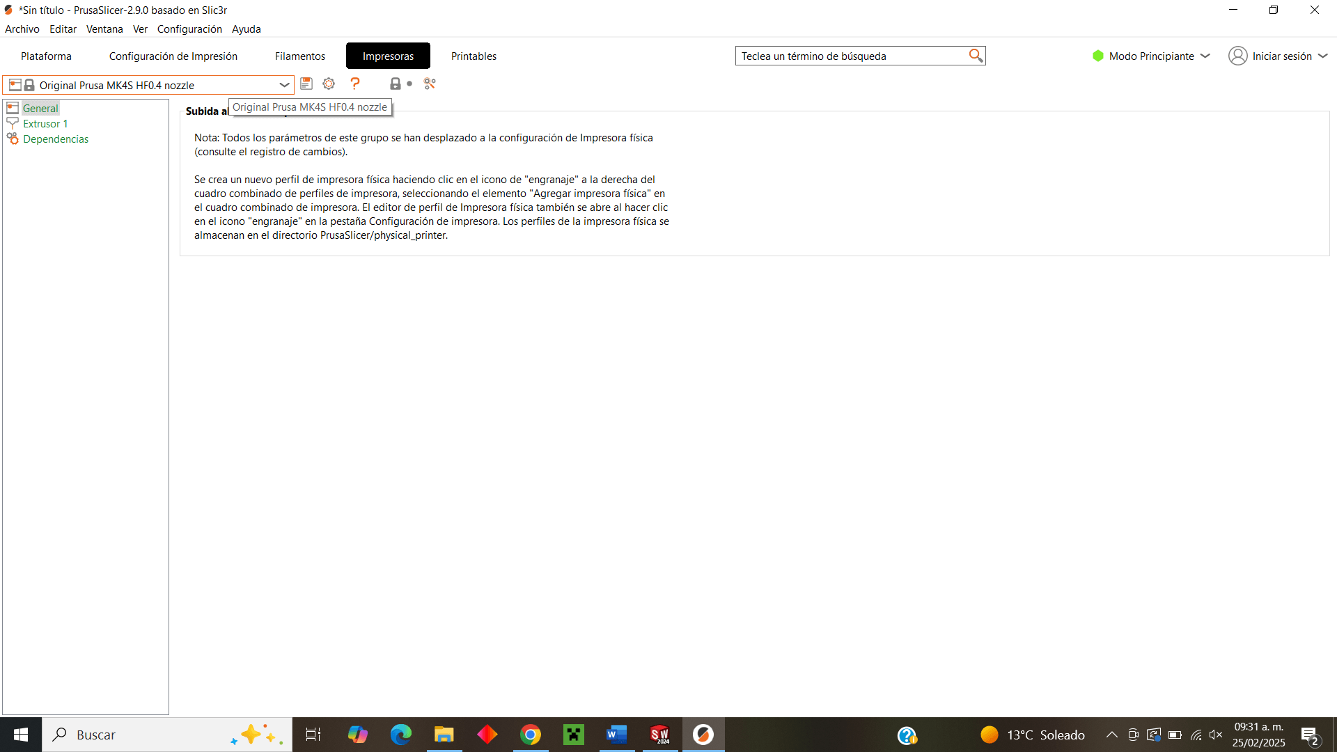
For 3D printing I will use the PrusaSlicer software version 2.9.0 where I will select the appropriate configuration for the printer I will use, in this case the Original Prusa MK4S HF0.4 nozzle
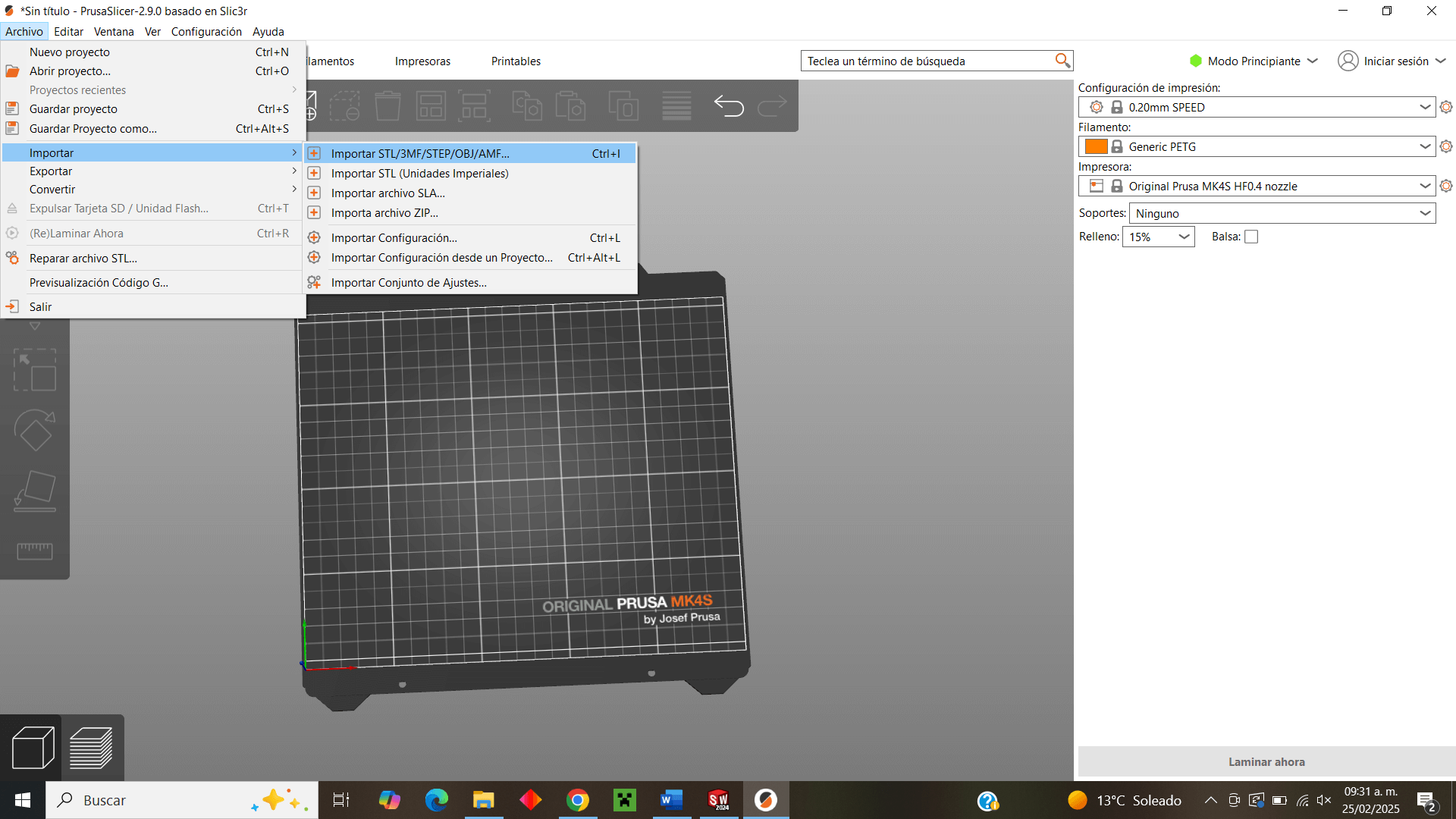
Now that I have specified the printer, I have the specific size of the print bed, where I can import the .stl file of my duck made in SolidWorks
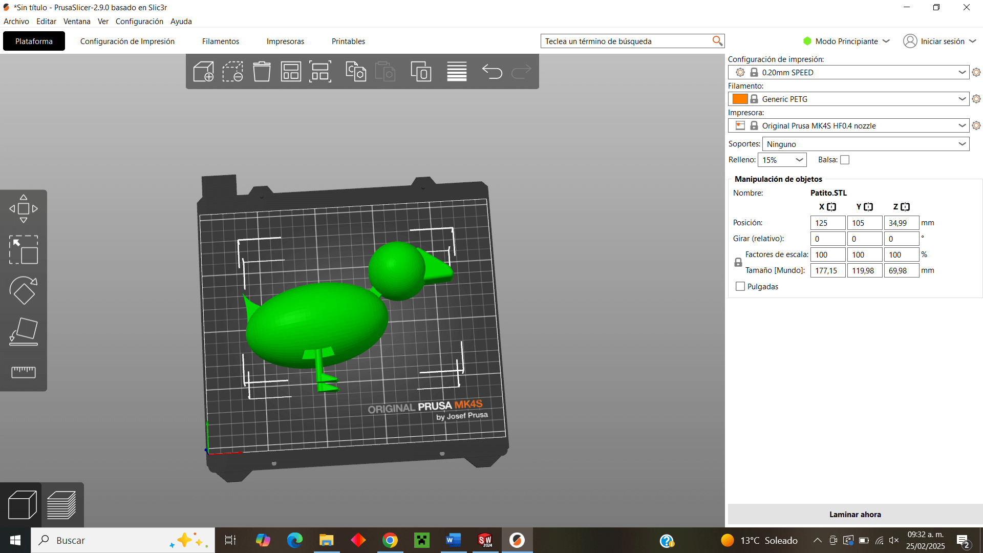
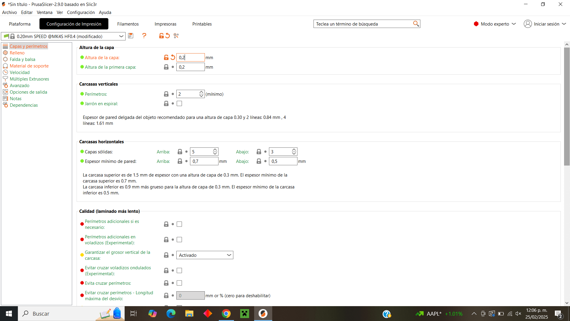
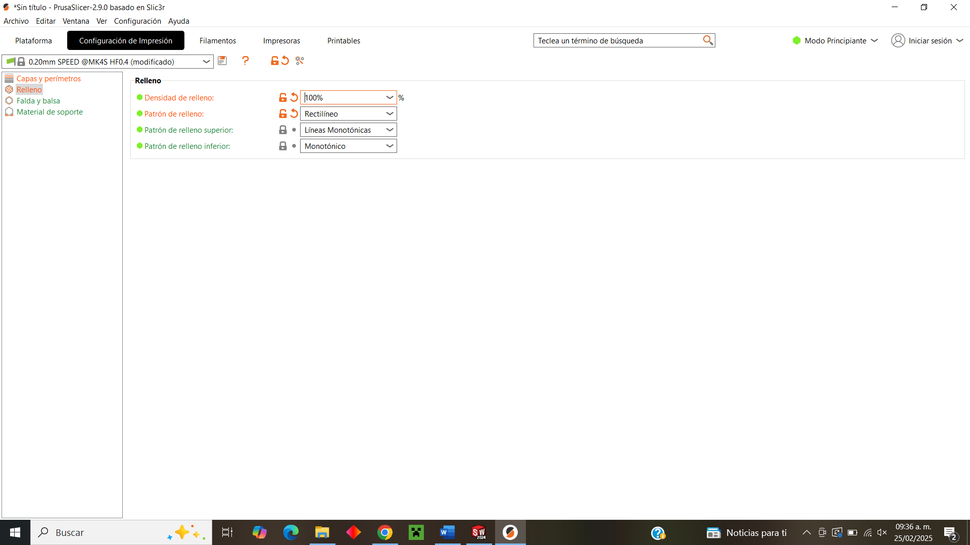
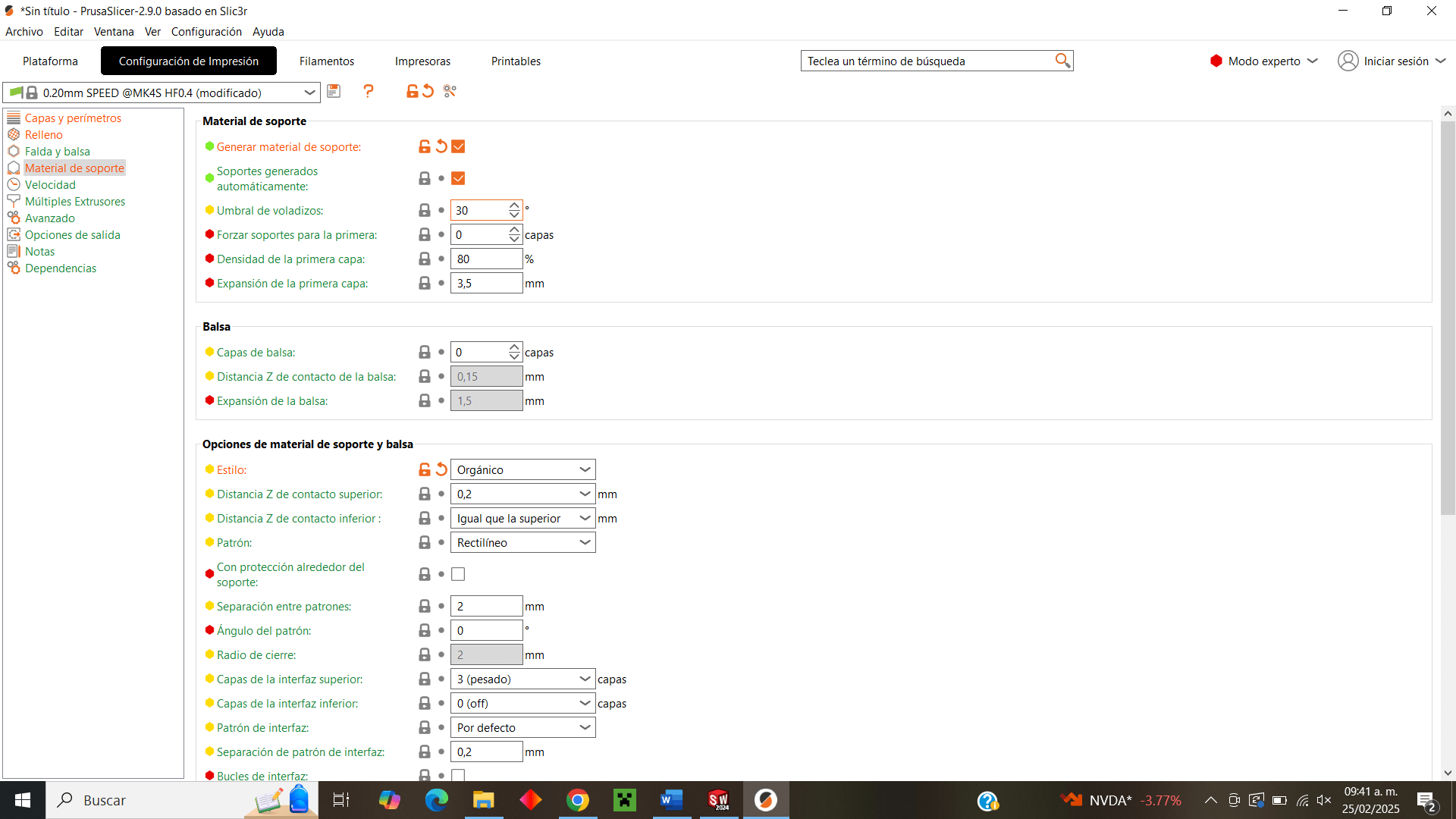
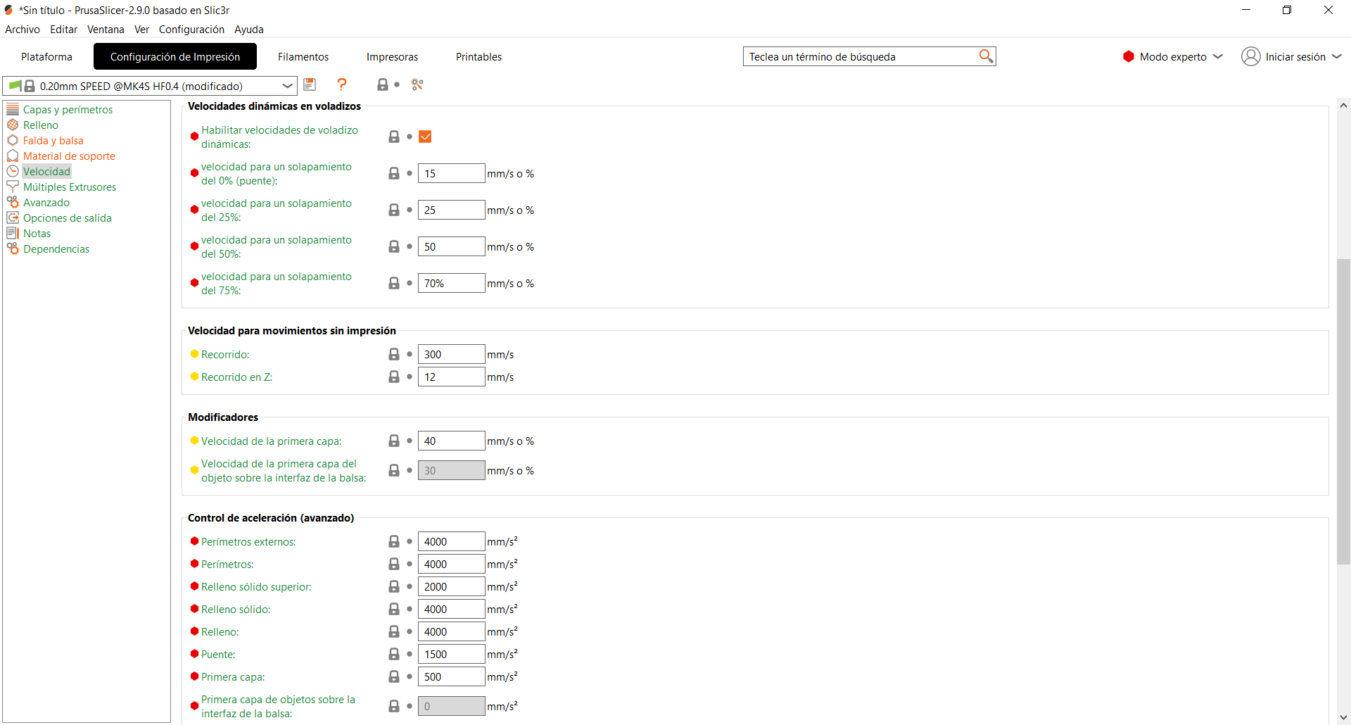
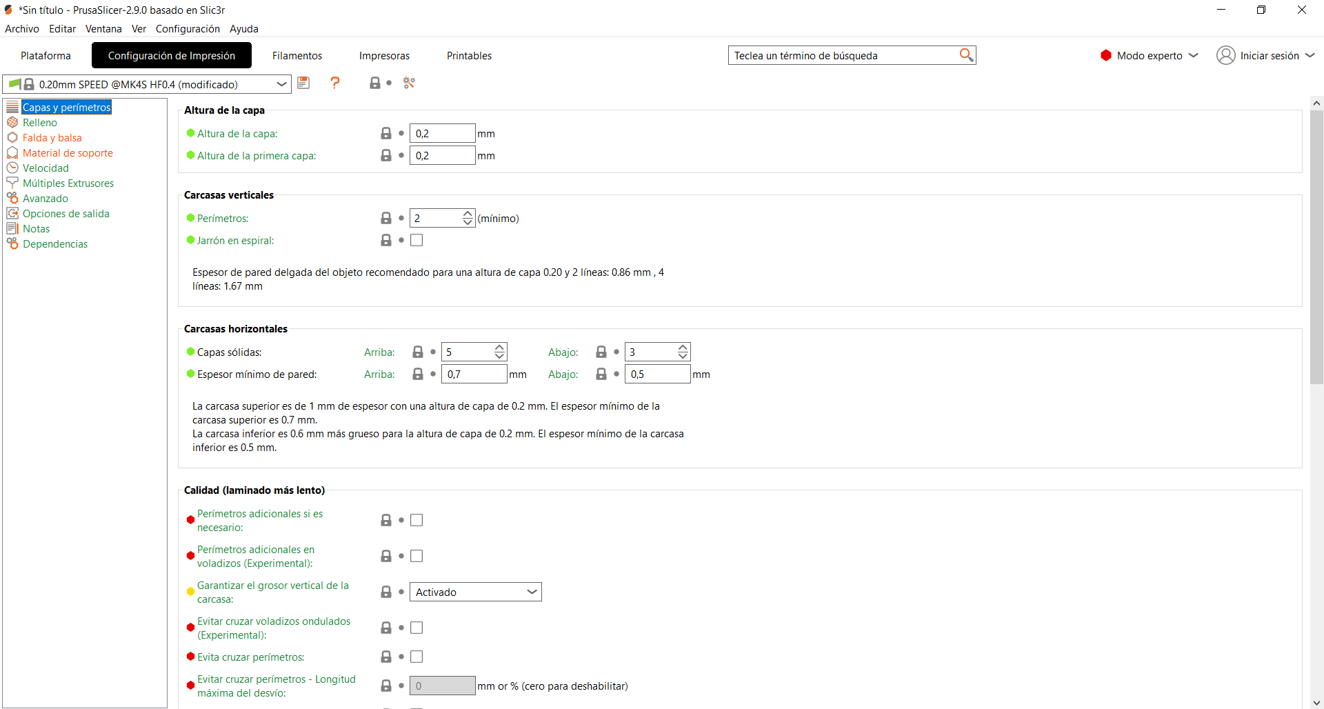
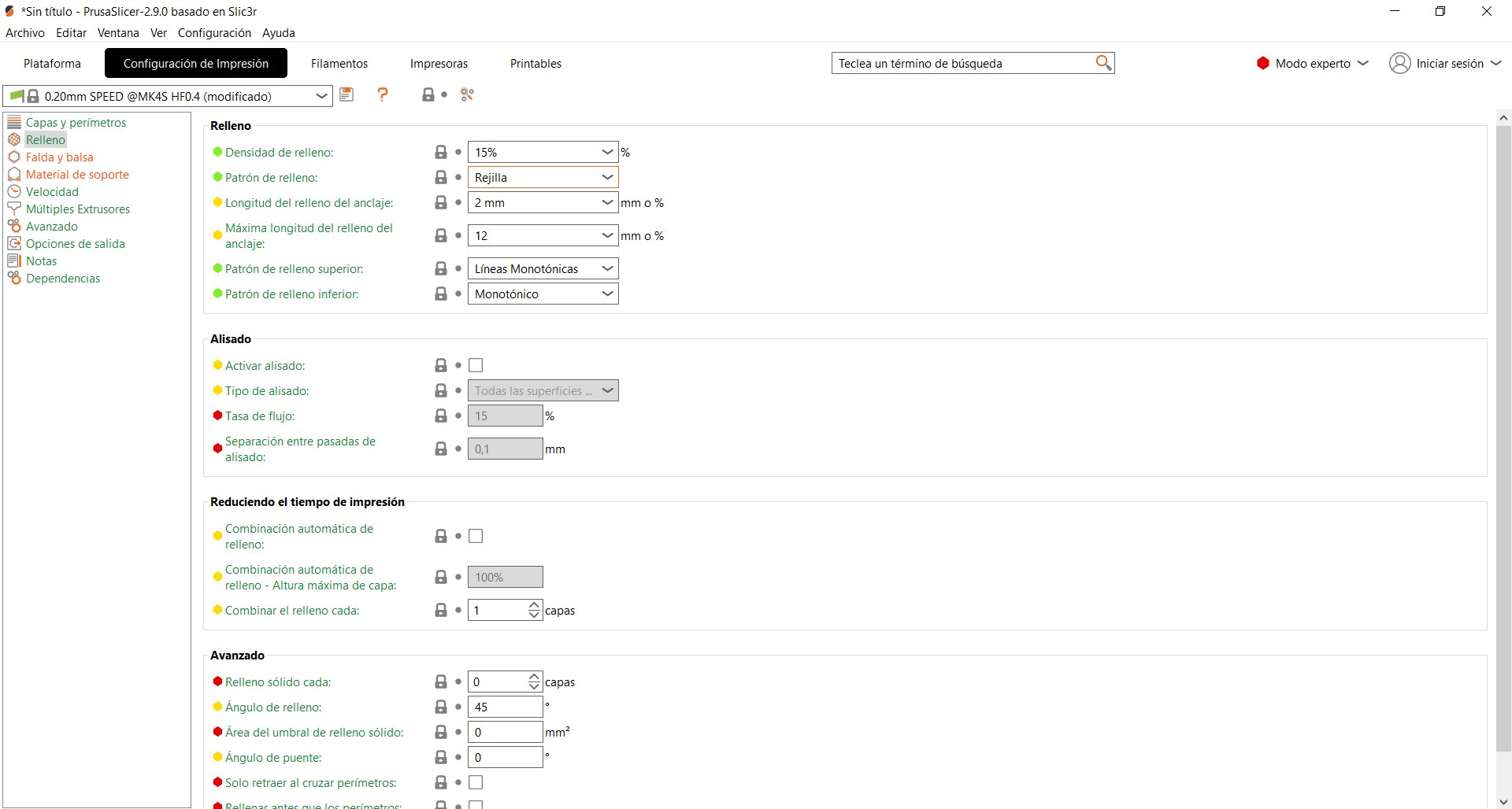
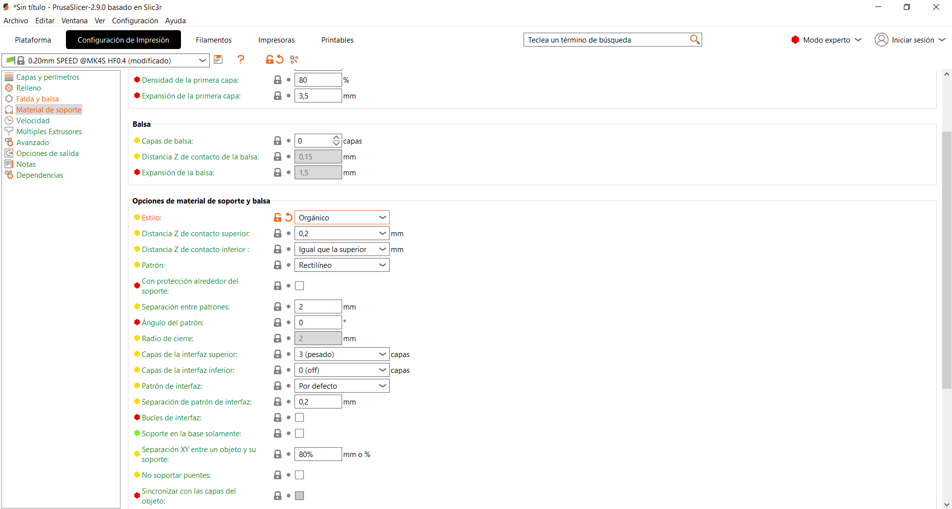
Now, the next step is to change the printing configuration parameters, among some changes I highlight the layer height (0.2mm), the fill density, the fill pattern (rectilinear), the support material style (organic), the nozzle temperatures specified for the printer and the material to be printed (PLA), finally deselect the G-binary code option since the printer does not accept that type of files.
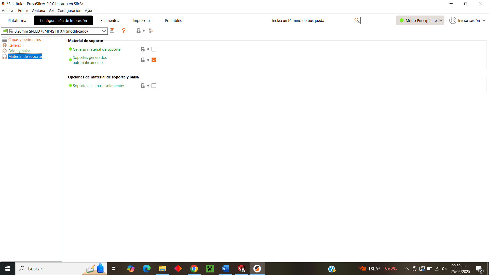
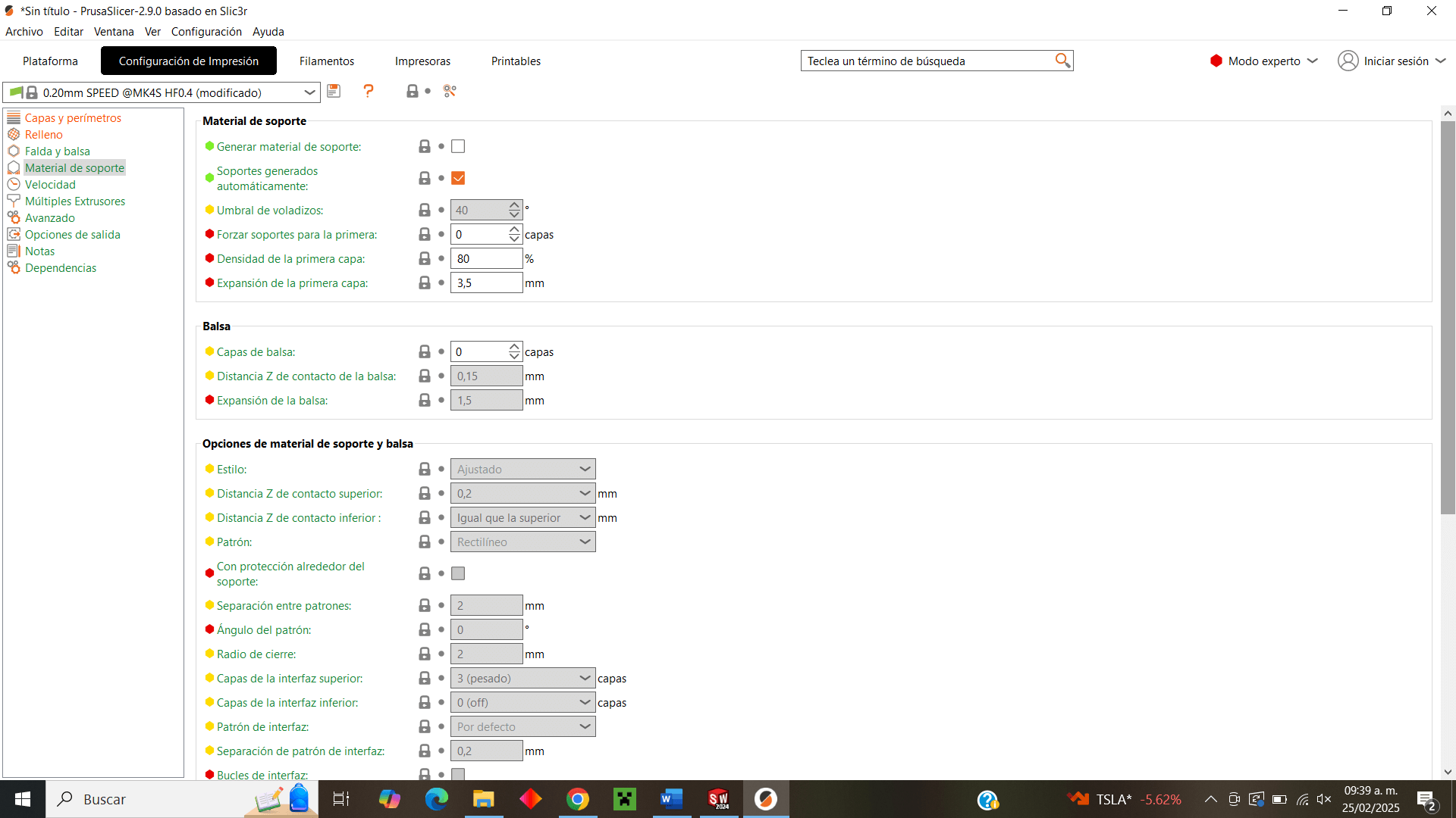
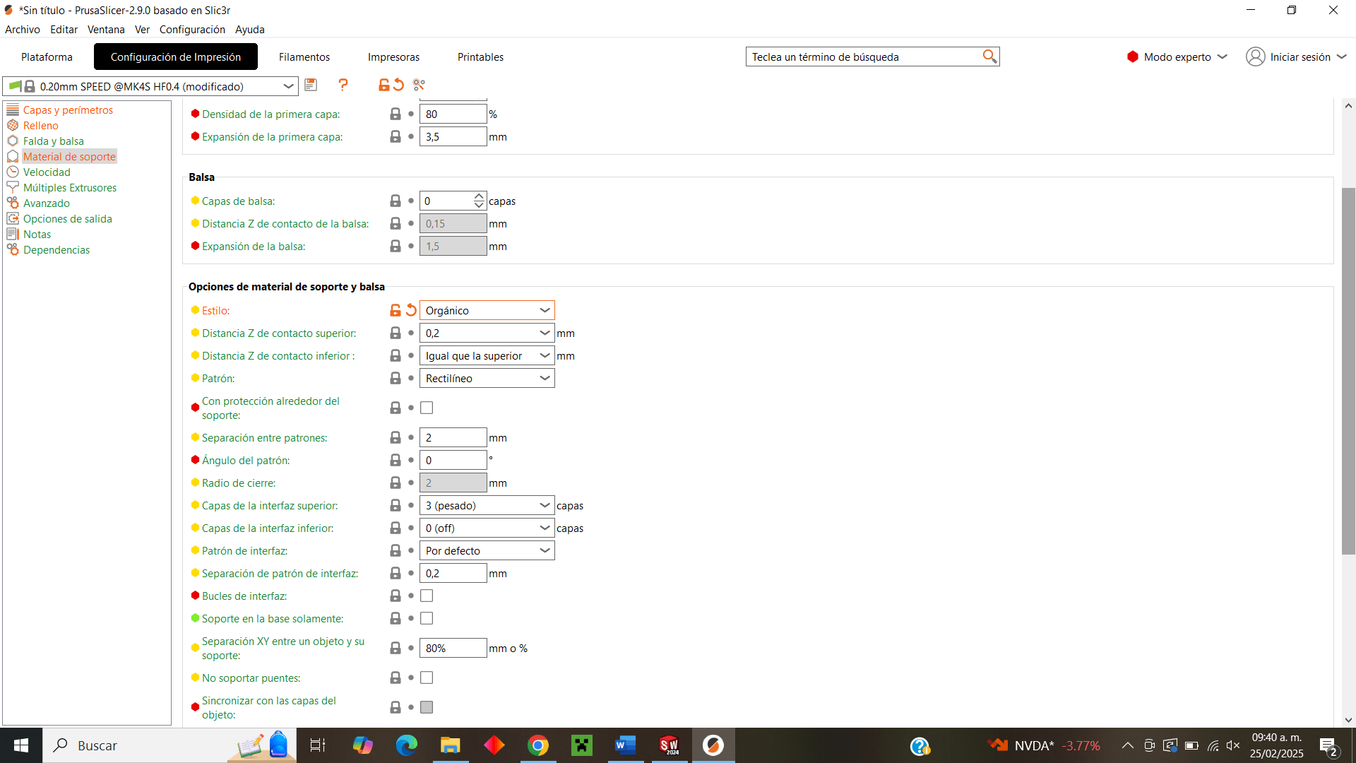
Finally, in the software, I slice the print to observe the automatic supports that will be placed on the piece, see the printing time and the amount of material that will be used.
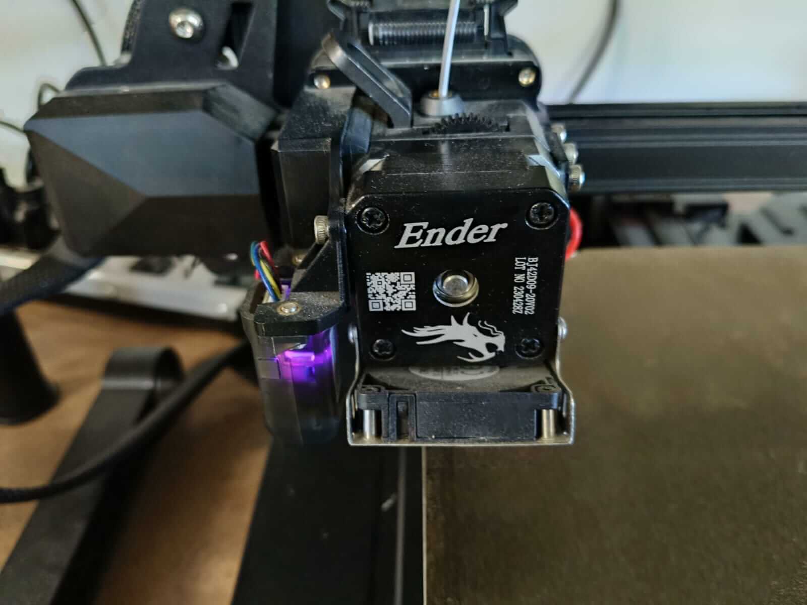
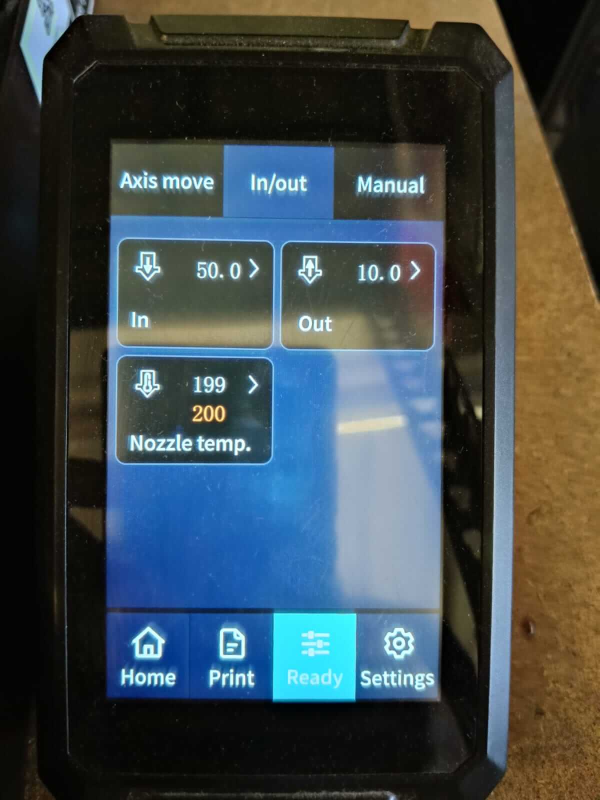
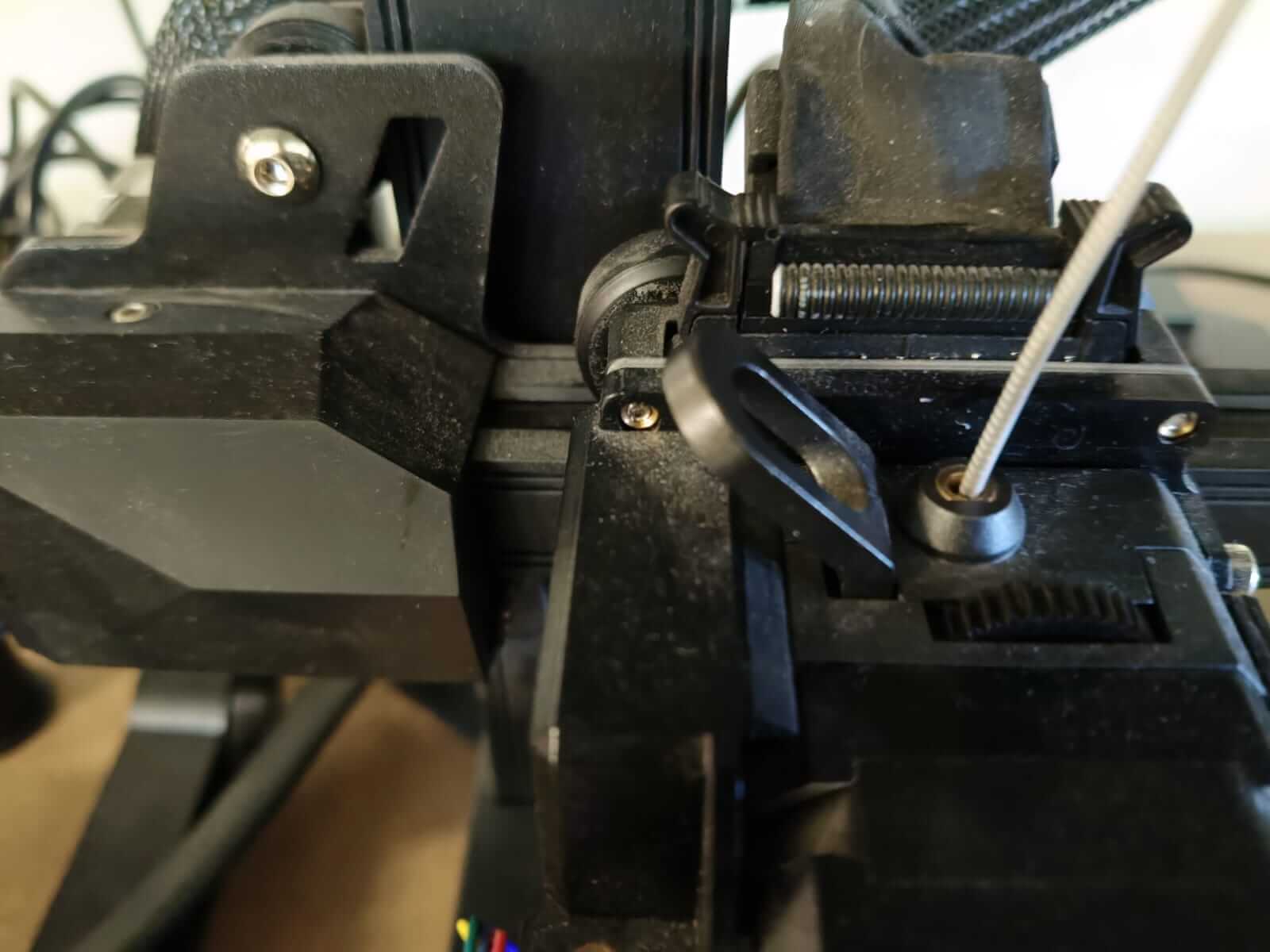
In the printer I was going to use there was a filament that I couldn't use so I had to change it, so I proceeded to heat the nozzle for a short time and then remove the safety lock and remove the filament, then place the new filament and heat it until the nozzle "spit out" the new filament and check that it had been placed correctly.


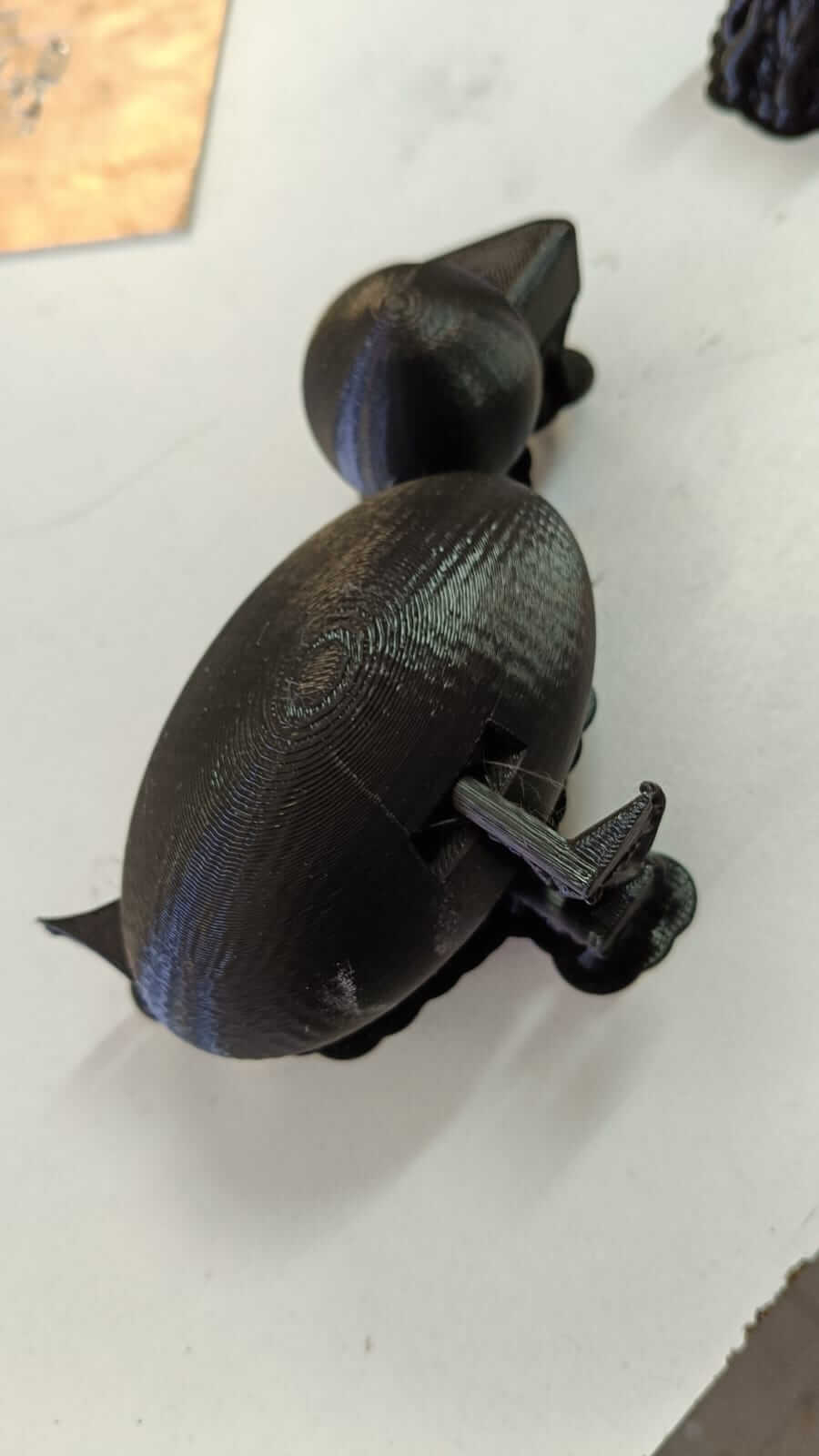
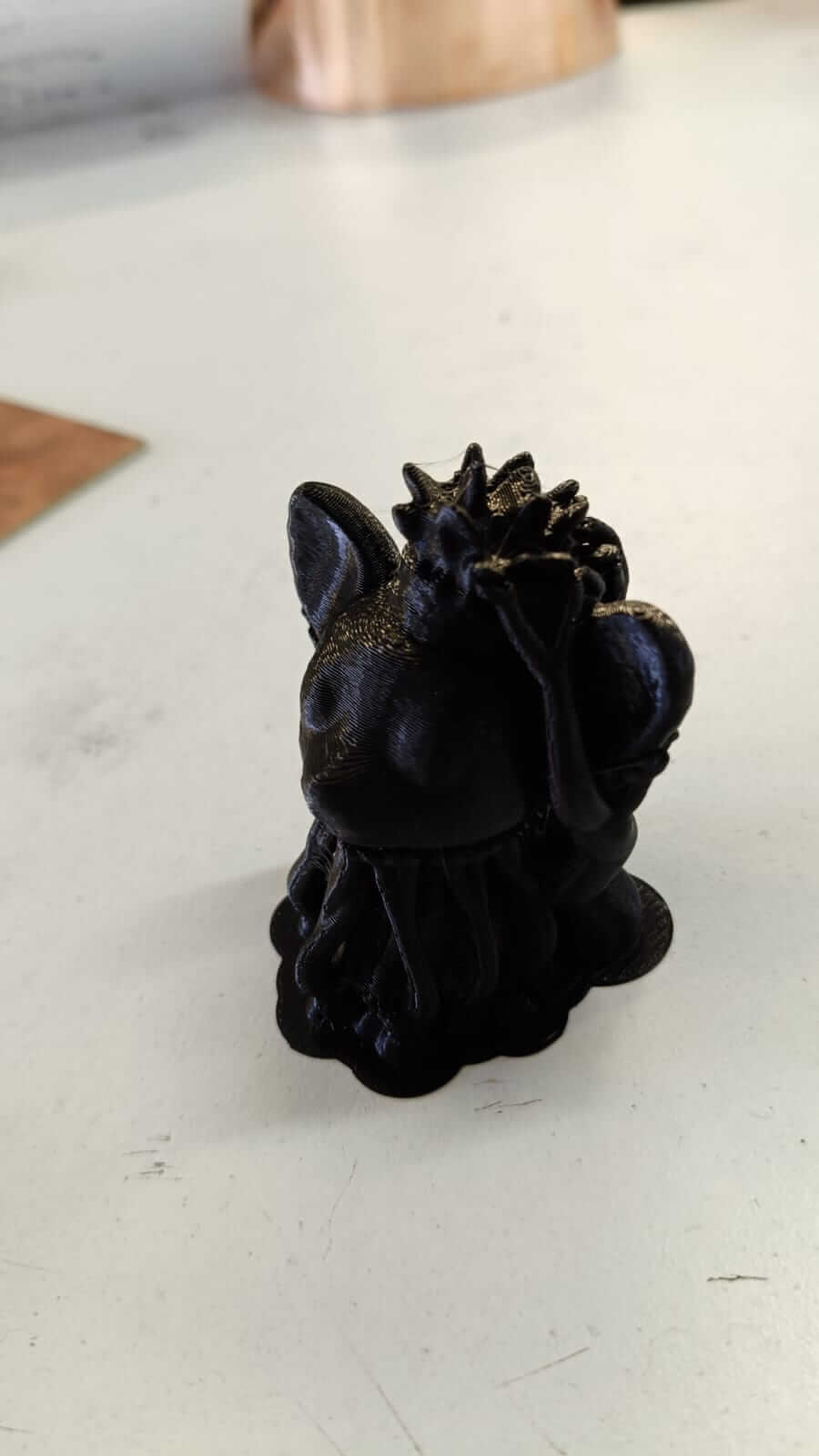
Unfortunately, my print went wrong due to three possible factors: one is that the filament ran out before finishing, another is that the material I put to print was PETG and not PLA which is the one I used for my duck figure, the last one has to do with the parameter settings, but it took me a little longer to come to that conclusion and I will explain it better later.

For the time being, I decided to redesign the duck, changing the design of the head joint and adding a joint in the duck's tail, as well as drilling the eyes in a different way.
3D scanning
For the 3D scanning practice, I decided to experiment with the Android app Polycam, as I was curious to see the scope and capability of the app to scan objects without using something as sophisticated as computer software or a scanner camera.
For this I will use as a test object a flowerpot of my pet that my sister has, it is a chihuahua dog.
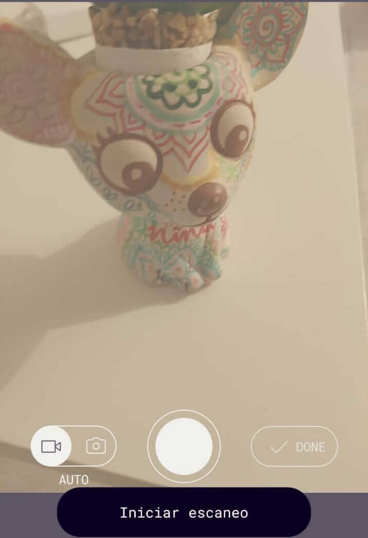
The application uses the front camera of the cell phone and starts when you select "start scan", then it begins to take several captures of the image as I move around the object, and something that I noticed is that the captures stop if they detect an image similar to those already captured, since it vibrates every time you take a photo, and it reactivates again when it detects a different angle that it has not captured, this allowed me to know that the scan was complete when the phone no longer vibrated
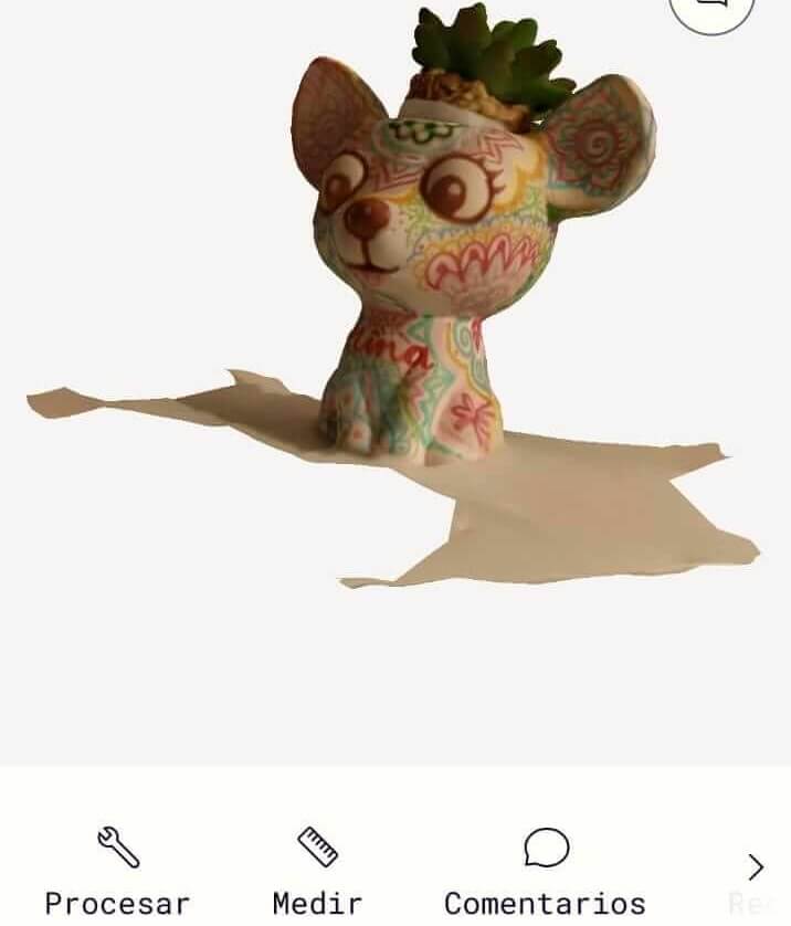
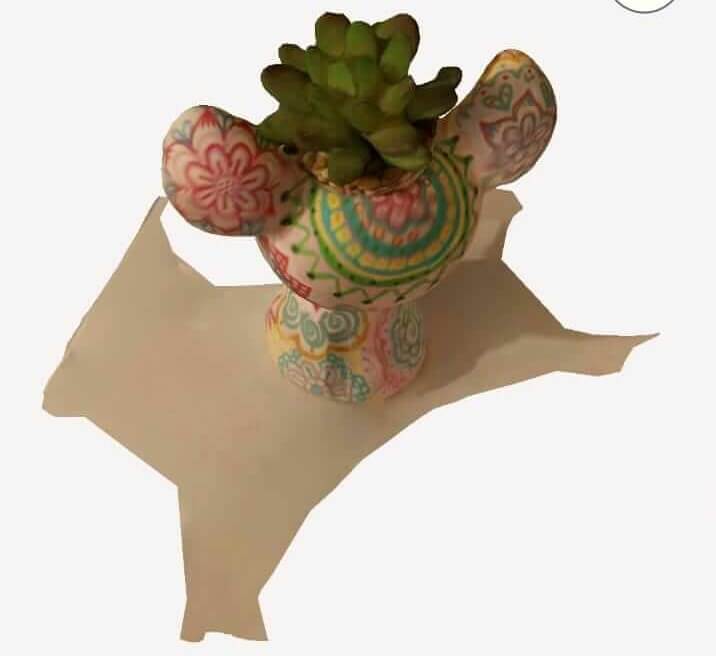
In the end, 155 photos were captured, processed, and the resulting 3D scanned model was as follows:
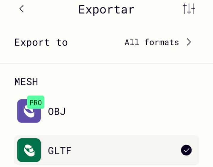
The next step is to export the file to a .glft format, however I emphasize that the paid version has more formats to export the file among several options
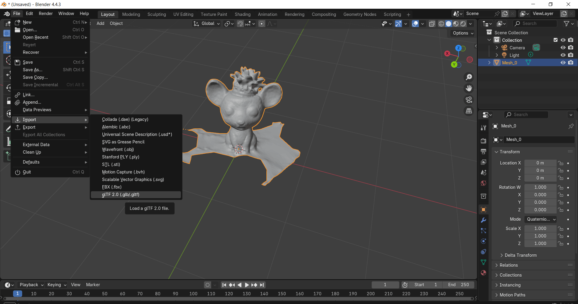
We open the Blender software and import the .gltf file and view the render
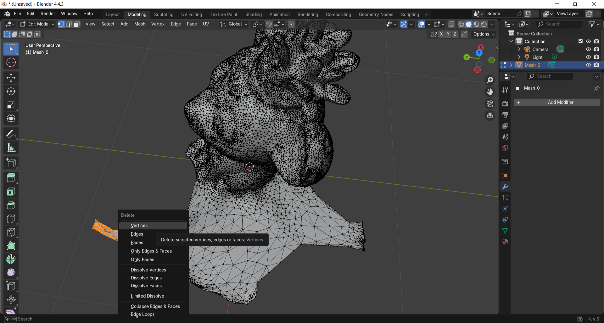
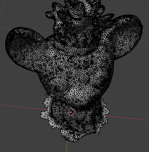
Now we look at the vertices of the render and remove some and clean the image to have a more defined figure
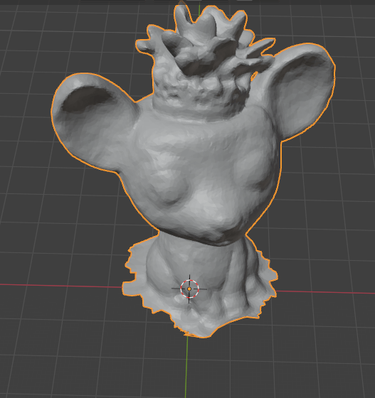
Now that we have the render, all that remains is to export it as an .stl file so that we can print it later
I open PrusaSlicer again and place both STL files, then I adjust the size of the pieces to a scale that I consider appropriate.
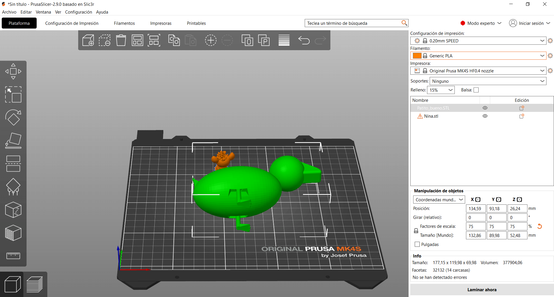
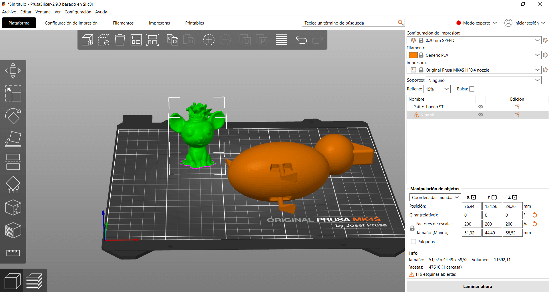
Now comes the other reason why my previous print could have failed, and that is that the printer I used was a Creality and not a PrusaMK4S, so the printing parameters such as speed or bed size were not the correct ones, so this time I made sure to use the correct printer for the one I was setting up the print for, I lowered the infill to 15% to avoid wasting material, I used the grid infill pattern to make a resistant figure and I continued using the organic supports
As a result, both prints came out correctly and there were no problems during printing this time.
From this week I can mention several things I learned about 3D printing that I didn't know, such as the fact that the size of the prints reduces as they cool and there is that margin of difference when designing parts, also how important it is to pay attention to the printing parameters I'm configuring and that they are correct for the right printer, in addition to using the correct material. As for 3D scanning, it was a new tool for me and I found it fascinating, as it opens up many possibilities for doing interesting things, such as making gifts that are scale replicas or having a 3D model of something real and basing it on your design, etc. The possibilities this practice opens up are extensive and quite useful for making a wide variety of projects.