3. Computer controlled cutting
This assignment consists of two parts, the first consists of a group assignment documenting the characteristics and capabilities of the laser cutters available at Fab Lab Puebla, in addition to the results of the laser cutting tests with respect to the power and speed assigned to the cut, in order to observe how "clean" and deep a cut is with certain parameters. Finally, adding information on cutting types to generate part joints.
Now with the knowledge of the group assignment, I have a clearer idea of the scope of the laser cutter, I will have to give total freedom to my creativity to design pieces of a construction kit and fulfill part two of the assignment, that is why my idea is to design a buildable photo frame where more than one can be placed and at the same time more can be joined together and put together a figure, the design will be for 10x10 cm paintings.Another point to complete in the assignment is also to learn how to use a vinyl cutter, for that I will design a figure in one of the software I used last week and send that file to the vinyl cutter.
3D part design
To carry out my idea, I took as inspiration the data provided by the group assessment from last year 2024, since it brings the information I need such as the measurements for flexible parts, joints or power/speed of the laser cutter

And exploring further on the page, I found the link to the page where he was inspired to get the measurements to give flexibility to a piece

I visited the source page and learned more about how this type of piece worked

I downloaded the file provided by the Fab 2024 page, to open it and observe the parmetric measurements used in this piece and thus use them in the design of my piece

I export the data of the equations used to parameterize

And I import the file where I am designing my piece

Using the equations I give measurements to the lines for the bending of my piece

As I change and determine the final measurement of my piece, I observe and verify that the values of the lines remain parameterized


Now I start designing the rest of my pieces that will be used to join the frames


I rounded its outer corners to give it a more "friendly" and less robust design, this would be the joining piece of the flexible pieces.

Piece to join the vertical and horizontal parts of the support frame

Part to join the frame with the flexible piece

Part to ensure the union of the frames

Frame piece (horizontal)

Frame piece (vertical)

All the pieces of the kit are designed, so it's time to save the file as a .dxf

When saving, this interface opens to select the face to be displayed in the dxf, so, I select the front

A window opens showing the dxf of the preview of the face that we selected, I make sure everything is fine and I save. It would be the same with the rest of the 3D pieces

Unlike the rest of the parts, the flexible part is in a sketch and not extruded like the rest of the parts, so to save it in .dxf the same procedure is followed with the difference that we will not choose a face or edge, but rather, we will choose the "Annotation Views" option and we will take the "Current" option as the view to export.

The next step is to open the SmartCarve 43 software, where one by one I export my .dxf files and place them on the sheet, however, during my process I notice a detail, that a line is missing in one of the cuts of my flexible piece

Therefore, I decided to use the software's own drawing tools and fill the gap manually

This would be the result, which looks good and closes the rectangle cut

The drawings of all the pieces have already been imported and inserted, but to move each piece individually without moving the lines of the drawings, I decided to group all the lines of a piece, doing the same with the rest of the pieces, which made it easier for me to select and move the drawings on the sheet

Finally, I copied and pasted the pieces necessary to cut and once ordered, I selected "File saves" which opened a window, where I selected "Generate OUD" which is the file I need to send to the laser cutter.

The laser cutter
This is the laser cutter that was assigned for the Fab Academy assignment
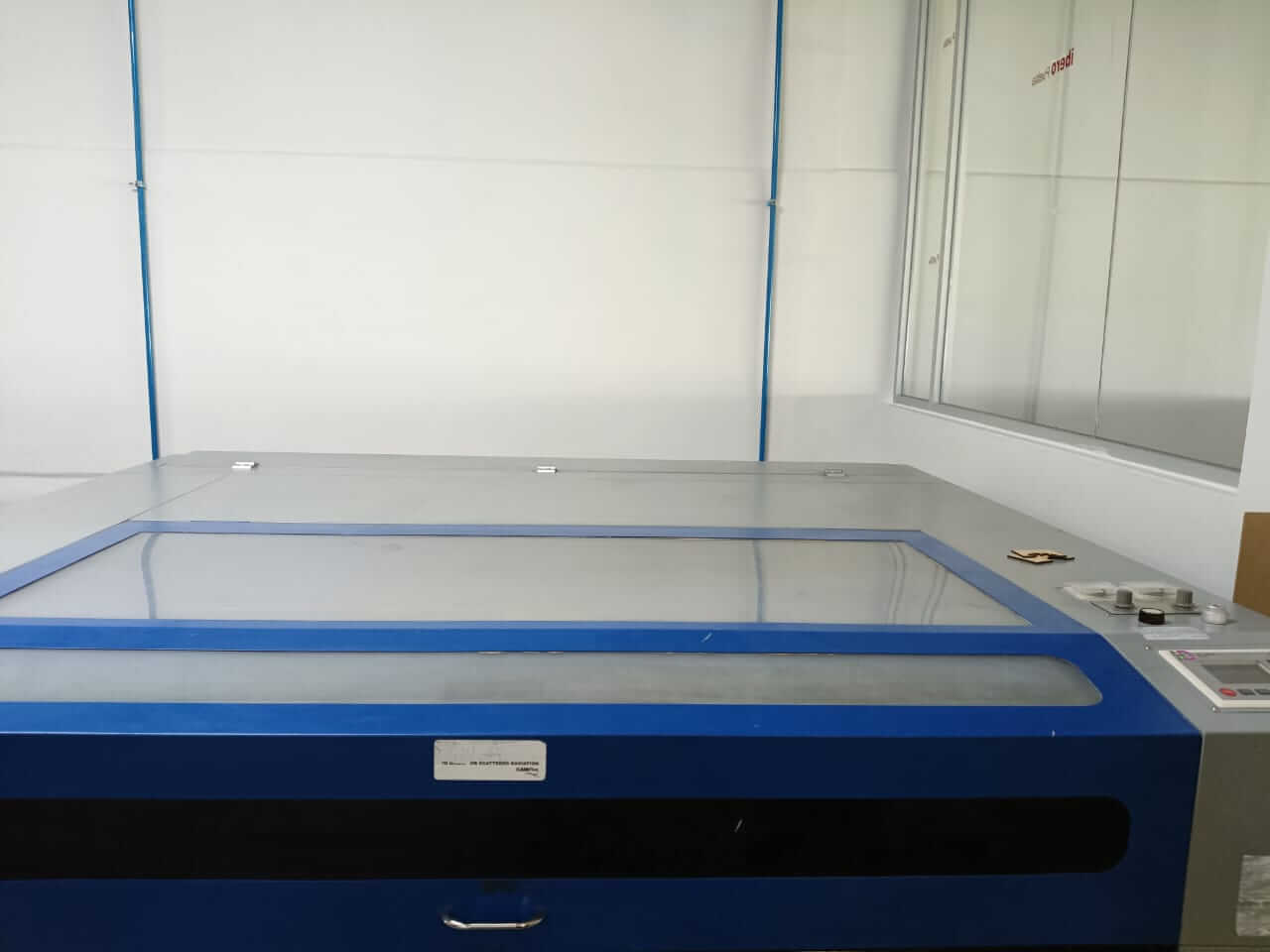
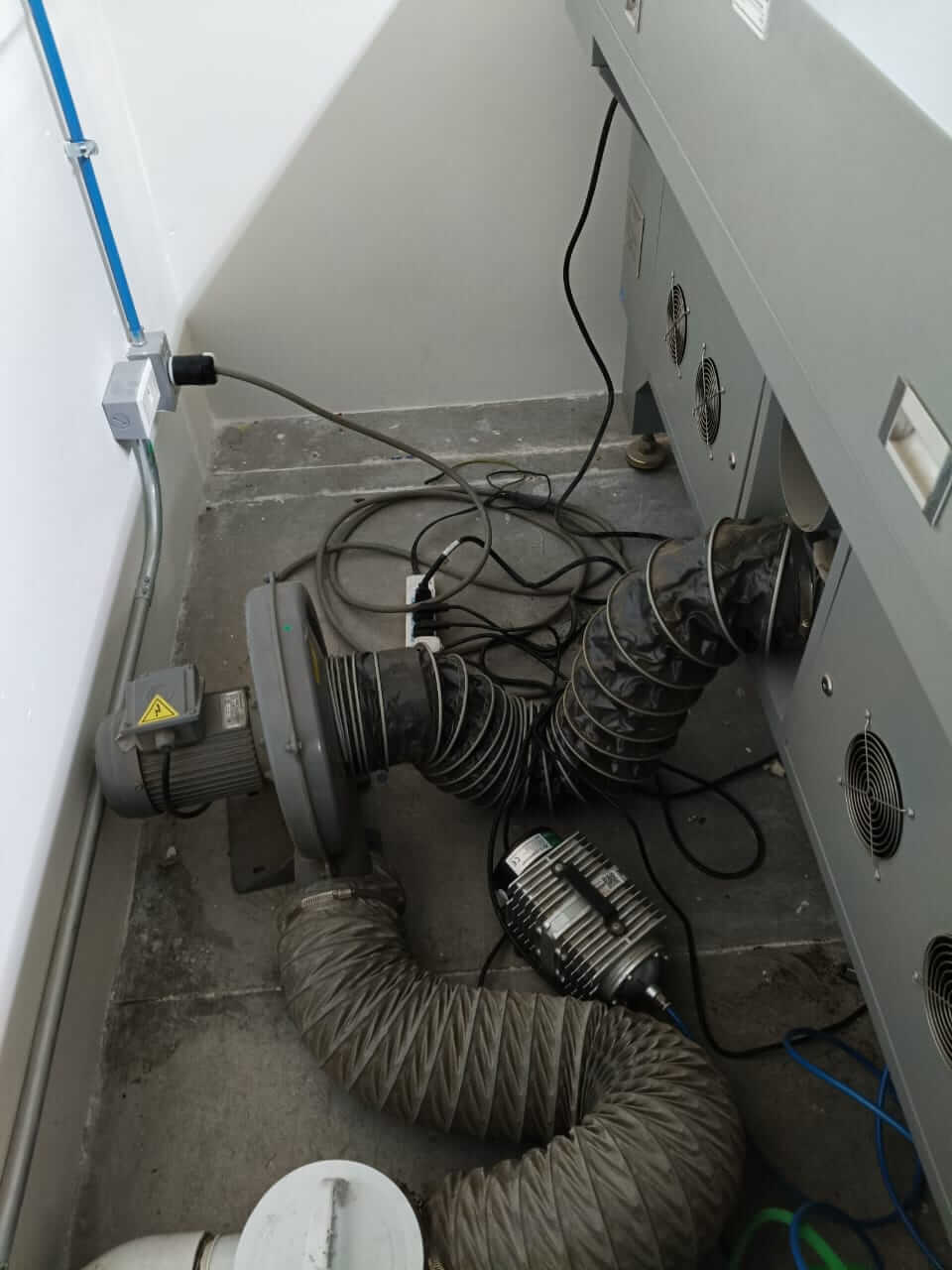
First we check that the cutter receives power.
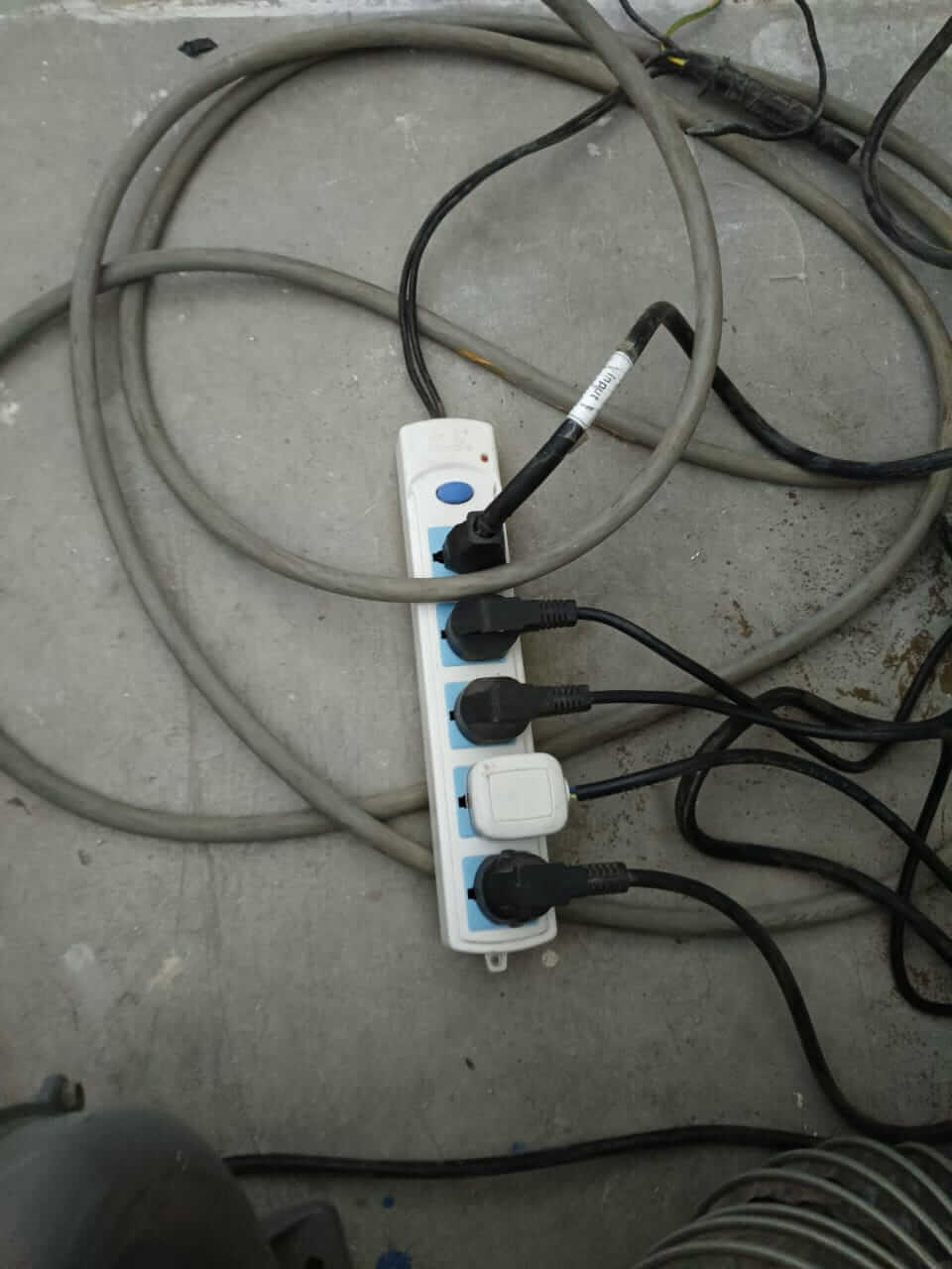
For that you press the blue button on the multi-contact
I then insert the key into its respective place and turn it, then turn the red knob and finally press the red button on the side of the mower to turn it on completely. I insert my memory with my file to cut, I save it in RAM and load the file, I mark the origin on a corner of my MDF and with frame I verify that I have enough space to cut, once I confirmed all this I pressed the "Start" button, all this through the control panel with screen.
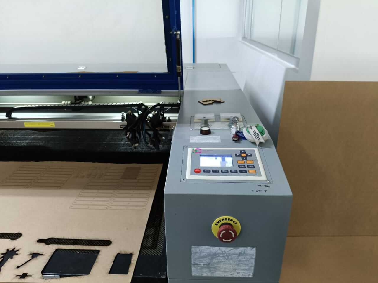
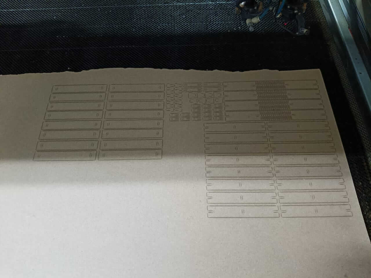
My cut is ready but I notice something, the depth of the cut was not enough and only the drawings were marked on the mdf, so I look at the panel and I realize that the parameters are incorrectly configured, I probably did not assign them correctly when saving the OUD.
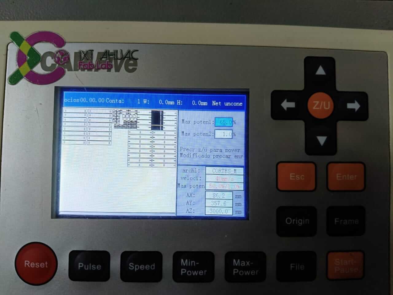
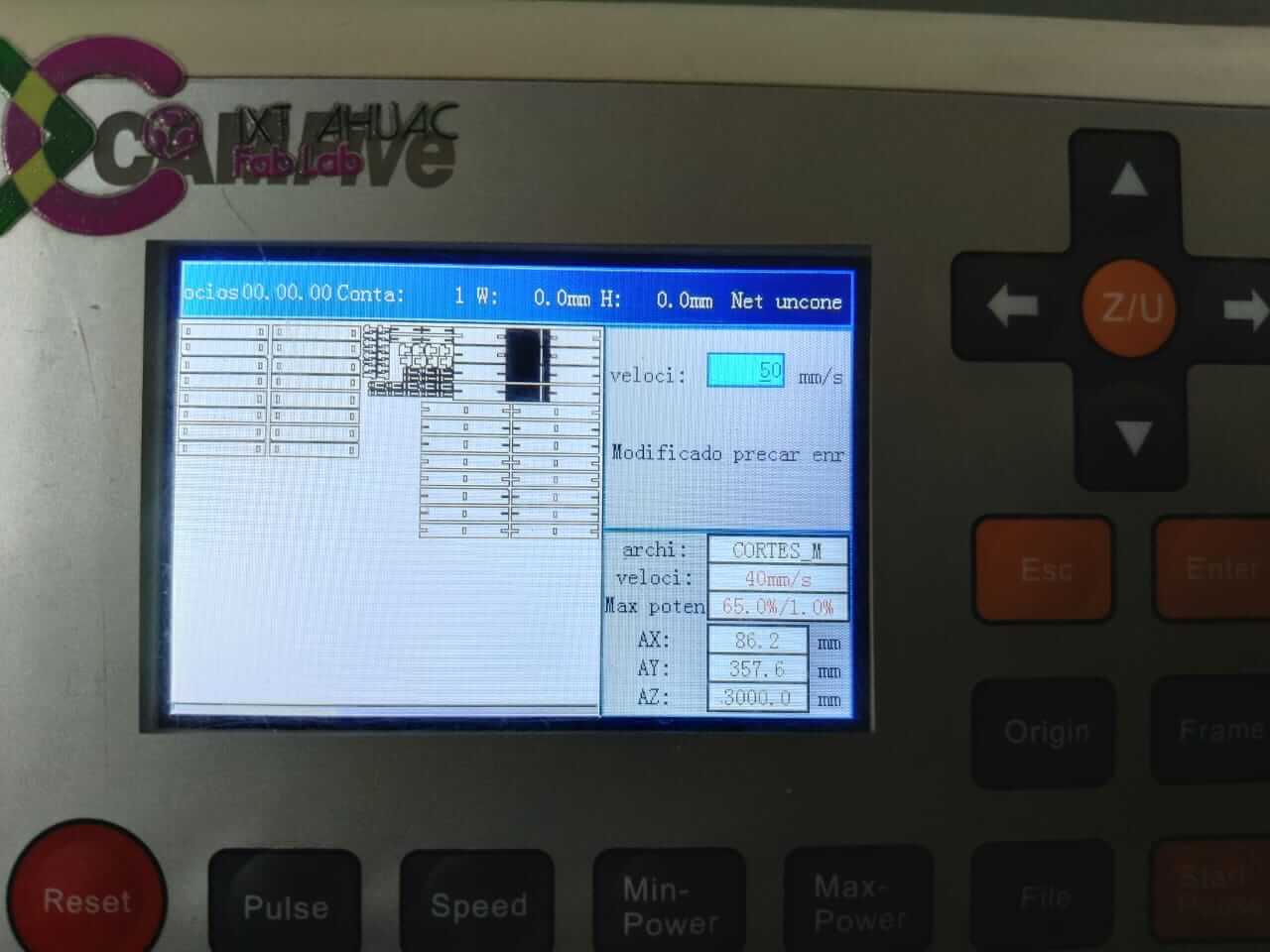
So I decide to set the power (65%) and speed (50 mm/s) manually
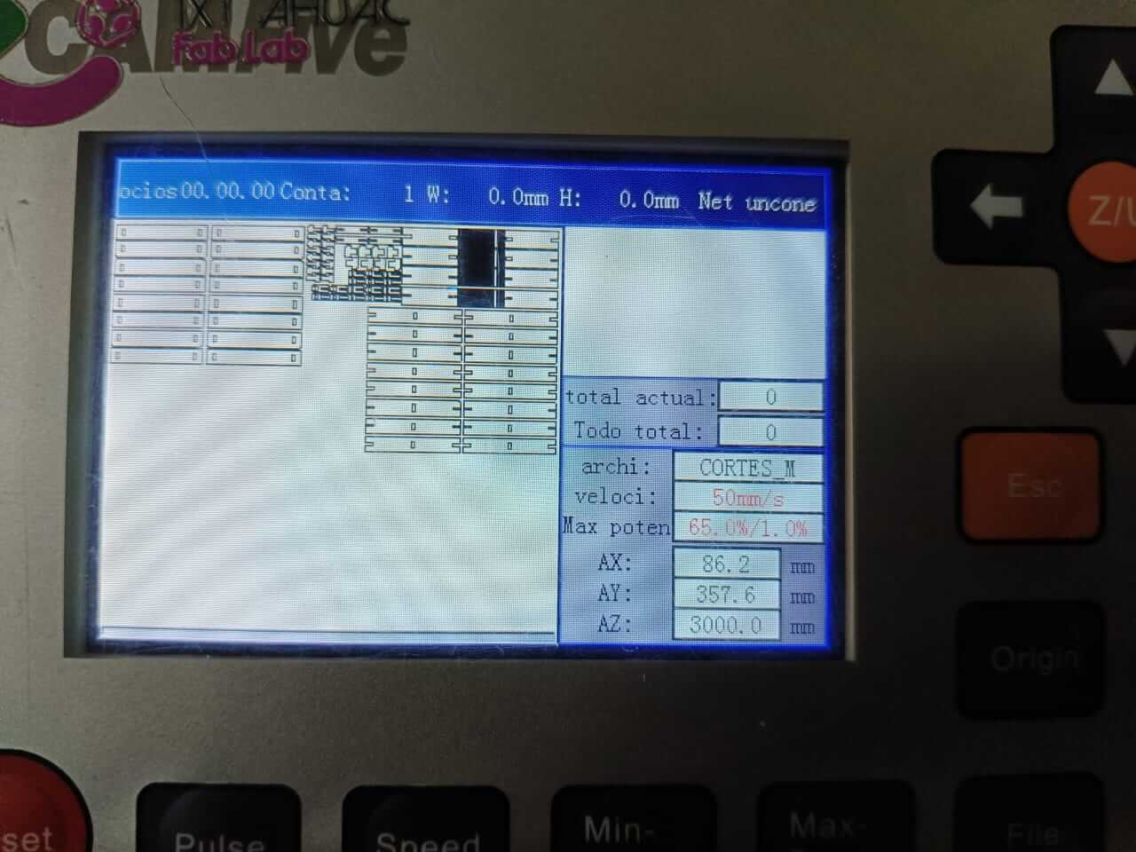
Finally the cutting of my pieces was successful, and here you can see the result of the union of my flexible pieces and others
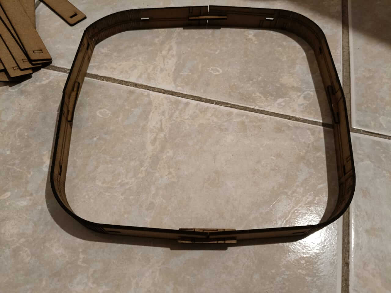
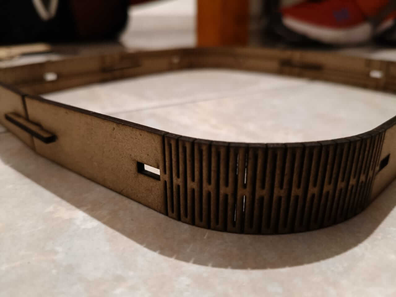
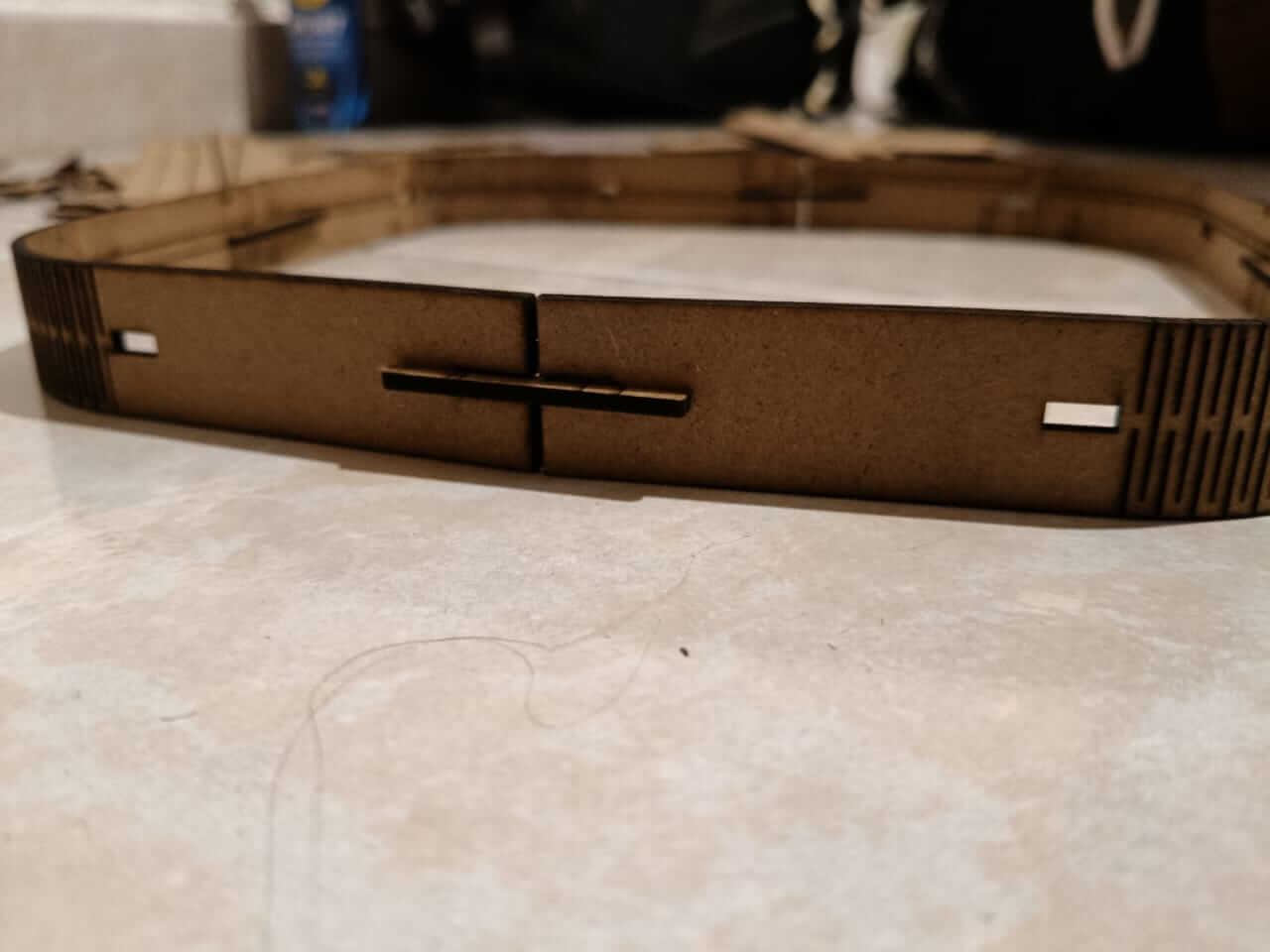
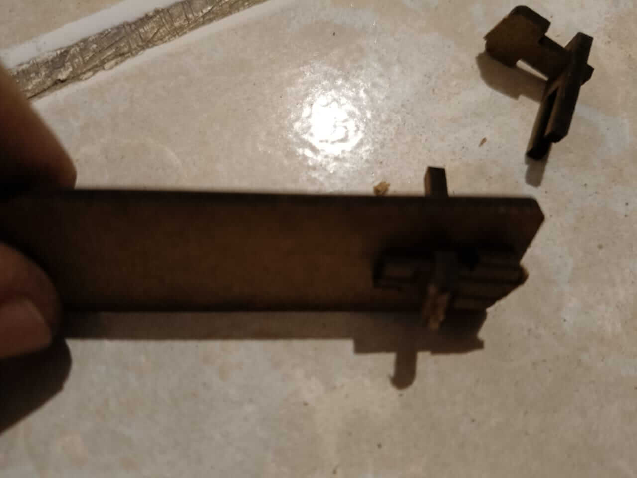
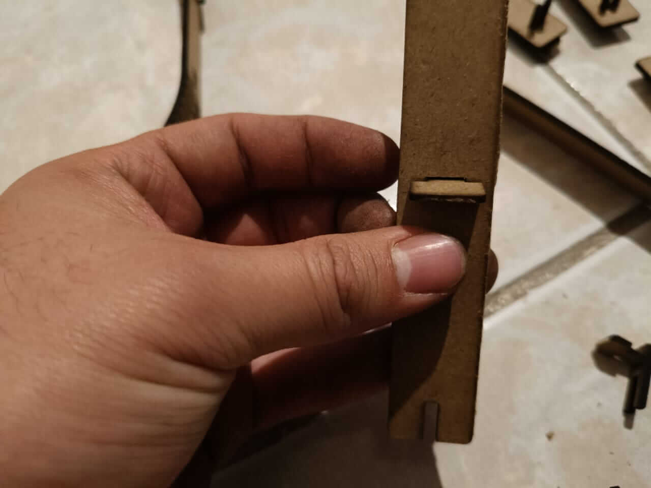
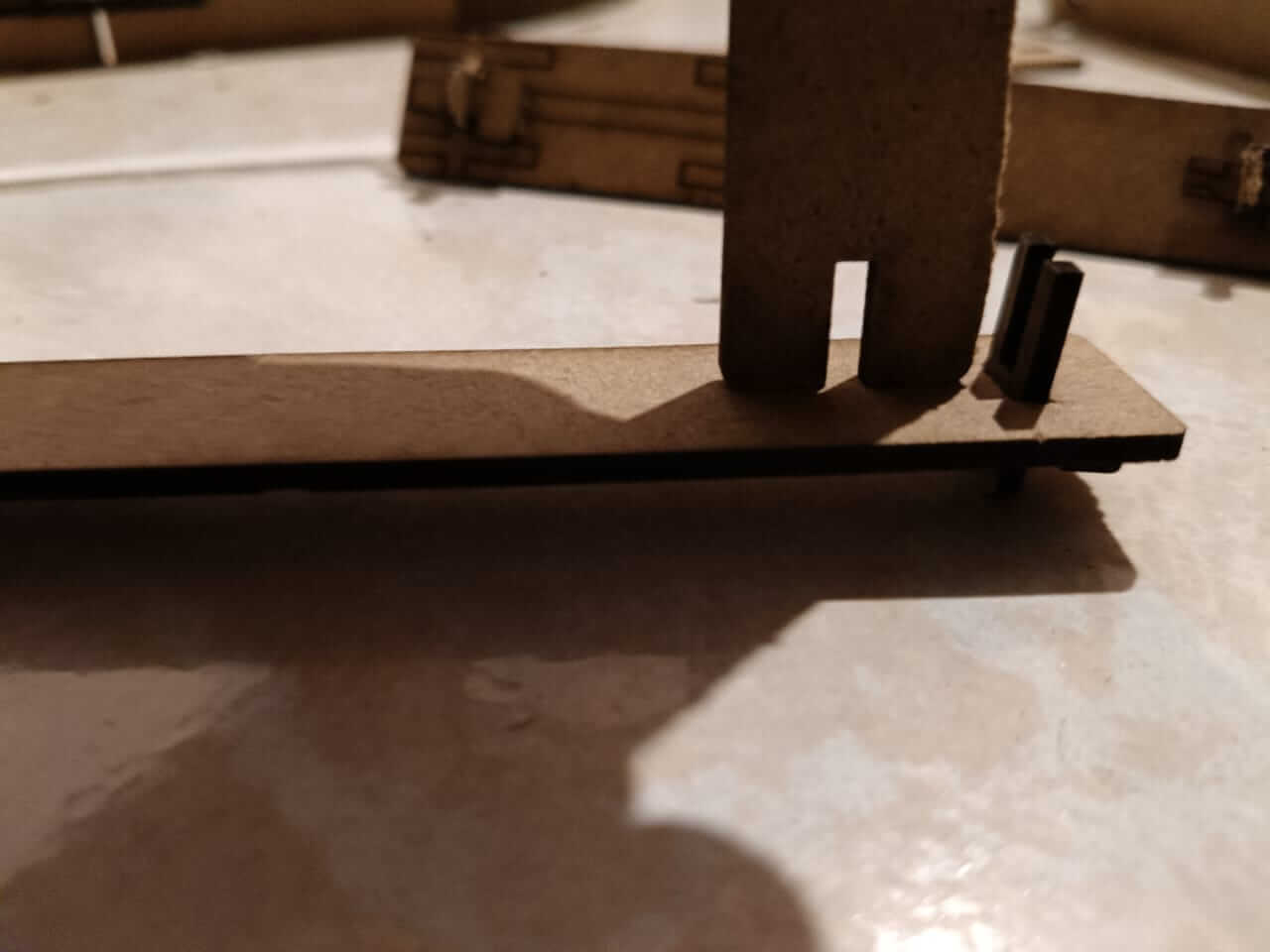
However, the piece that joins the horizontal and vertical part of the frame is not well designed, since the fit does not reach the necessary end, so I will have to make some adjustments to the design and cut again.
