Computer Controlled Machining
Plan/Dates:
Hopefully, the 27th time's the charm! — Grant Imahara
ZB FAB Academy W07 Planning/Documentation
Process This Week:
- SAFETY FIRST!!
- CAD a BIG object
- Transfer to a CNC toolpath
- SAFETY FIRST (again)!!!
- Mill
Tasks This Week:
Group assignments:
- Do your lab's safety training test runout, alignment, fixturing, speeds, feeds, materials, and toolpaths for your machine
Individual assignments:
- Make (design+mill+assemble) something big (~meter-scale)
- Extra credit: don't use fasteners or glue
- Extra credit: include curved surfaces
Below, I walk through some of the notes/screenshots that I have from my work this week and explain my thought process as I was completing my assignments. *Note that as of 3/12/25, I was not able to finish the milling of the table because of a scheduling conflict at my lab. As a result, I do not have my finished product images, but the milling will be completed by EOD on 3/12 or 3/13 and my page will be updated hastily thereafter.
- Computer Controlled Machining Group Assignment:
- Our CNC Machine is a 96x48 Forest CNC Convert-A-Table. This means that it is a CNC plasma table AND and a CNC router. It can plasma cut metals when the spoil board is removed and the bed is filled with water. After draining the water table the spoil board is replaced and secured, softer materials such as wood and plastic/polycarbonate can be cut. We create the part files in OhShape, SolidWorks, or Fusion 360. For non-metal cuts, we generate tool paths using Vectric’s Cut 2D Pro
- CNC Terms
- CNC: Computer Numerical Control
- End Mill: A cutting bit used for milling
- Spoil Board: A sacrificial surface from which to hold objects down on and not be overly concerned when an endmill goes too deep and cuts into it.
- Alignment: Levelness and straightness of the spoil board
- Fixturing: How material is held to the spoil board in order to be cut on the bed
- Flute: A channel on an end mill to direct the cutting debris
- Runout: Runout refers to inaccuracies in a tool or piece of equipment that cause it to spin off its ideal axis. Spindle runout occurs when a spindle no longer rotates on its intended axis, which can result in: Issues with tolerance control. Inaccurate machine registration. Excessive chip load.
- Toolpath: The path that the endmill follows to cut the material
- Tabs: Small sections of material that the machine does not cut to hold material in place when cutting through the entire thickness of material
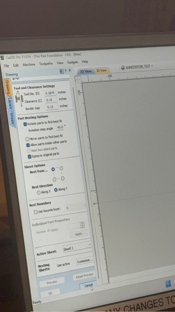
- Creating tool paths in Cut2D Pro for CNC machines involves several steps. Here's how we do it:
- Import files into Cut 2D Pro (.dxf files are preferred).
- Set Material Size: Ensure that the overall material size matches or exceeds the size of the finished product. You can do this in the Job Setup section.
- Set X, Y and Z zero for material: Manually move the router head to the X and Y the respective edges of your material alining with the tip of the bit. To set Z zero manually move the router head to the middle of your material and use the Z-zero touch pad.
- Select Vectors: Start by selecting the vectors you'll be using for machining onto appropriate layers (if applicable).
- Choose Tool path Strategy: Work through the tool path strategy icons (pocket cut, profile cut, engrave or drill) you wish to use to machine the job. This will calculate all the required tool paths.
- Preview Tool paths: After creating each tool path or at the end of calculating them all, preview the tool paths in the 3D view. This step is important to verify the position, detail, and look of the overall finished part.
- Save Tool paths: Choose the appropriate Post-processor. In our case we are using the ForestCNC router.
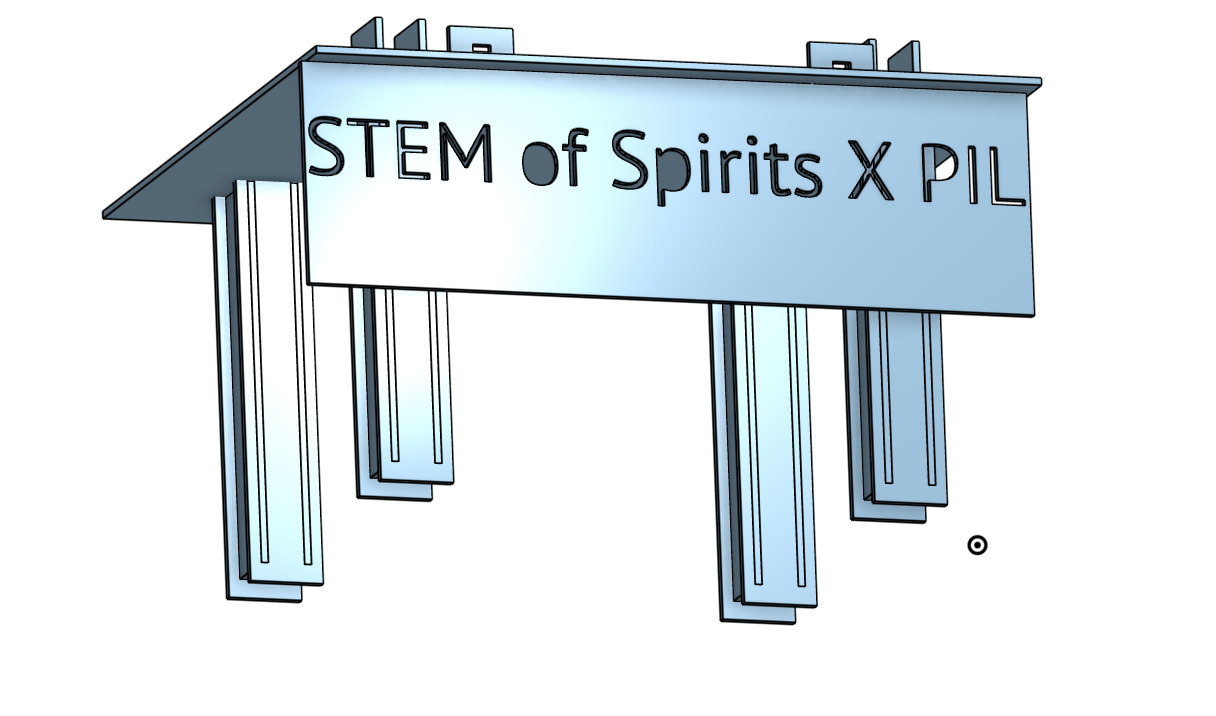
- For my individual assignment, I created a table for the PAST Foundation's annual fundraiser STEM of Spirits. I was intruiged by the challenge of creating a table that required no fasteners or adhesives, so in my CAD, I strived for a design that allowed for that.
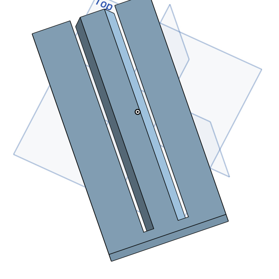
- I created two versions of legs, one that had a triangular design, that, did not end up working as a result of a limitation of our CNC machine. The second set of legs featured a square design that attached, through slotted sections to the table top.
- For the front of the table, I designed an apron that featured text and attached via two slots and tabs to the table top, which allows for some dissabsembly.
- Before doing anything else, I double checked the fit of my parts in OnShape, to ensure that both a.) I had accurately reflected the thickness of my material in all parts, through good parametric design, and b.) that once cut, each of the pieces would actually fit together (seeing as everthing went well with the milling). (In the picture above, you will see that posts stick out of the top of the table, these are there as a feature that helps to secure the boxes that the PILs come in).
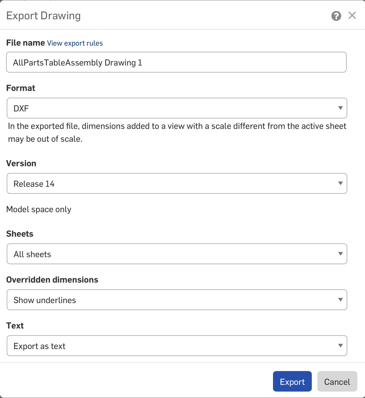
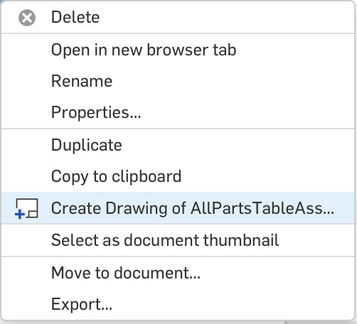
- I was able to export the entire assembly that I CADed to a drawing file in OnShape and then export that as a .dxf to our CNC table.
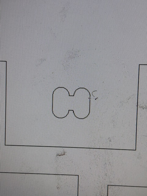
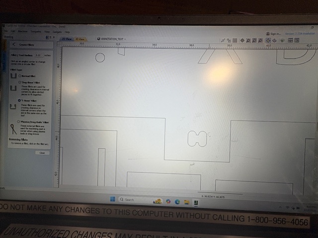
- In order to make the press fit legs fit into the pockets cut in the table tops I had to modify the corners of the tool path. CNC routers cutting inside edge paths will not make square corners so I had to do the "dog bone" (actually "T-Bone" in this case) corners so the square corners of the leg tabs wouls fit.
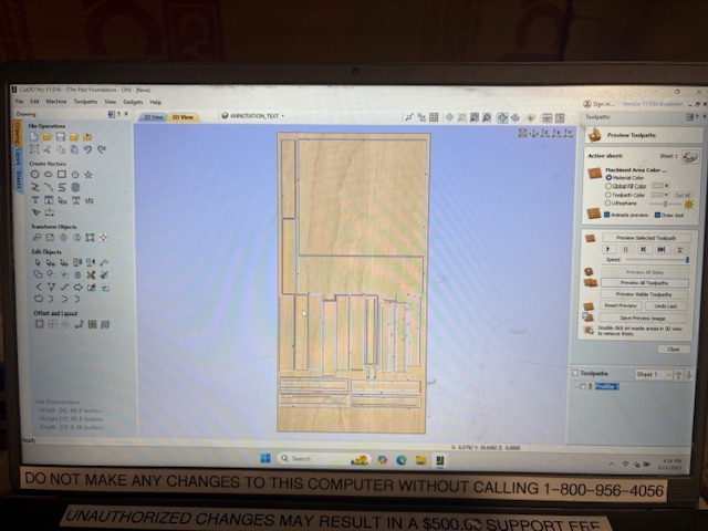
- I also had to ensure that, since I wanted to keep the internal parts of my lettering, that I attached them to the surrounding material, so I added some tabs in Cut2DPro in order to have them stay attached during the milling.
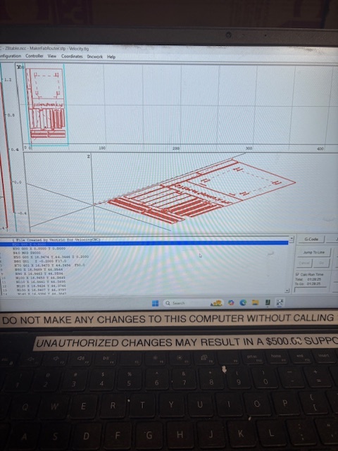
- Images of toolpath:
- Once I finished preparing the toolpath (adding tabs, fixing vectors, etc.) I milled, and finished the table by attaching some preprogrammed (sorry, Neil) LED lights to the back side of the apron, and sanding. For the holddowns, I used both clamps and screws and stopped the milling as I went in order to make sure that all pieces stayed down as necessary.
- Unforturnately, one of the big issues from this week is that my first time actually getting to use our CNC machine, including the software, was on Tuesday afternoon (as noted above because of a comedy of errors in scheduling) this means that my documentation for this week is kind of rushed and should be more flushed out in terms of pictures and layout. If I had more time, I would have finished the instructional video that I am creating and would have added sections of it to the page for each of the steps to outline everything in my project. Moreover, I could have used clearer stills from that instead of taking rushed images on Tuesday afternoon in order to show off some of the elements of the CNC that are currently challenging to see/understand.

- One of the biggest improvements that I could have made to my process this week would have been to start off with a more clear design of what I wanted in the end before beginning. I knew that I would need a lot of time to design this because it is well outside of my normal CAD wheelhouse, so I just got right into it without enough planning
- In my original, triangular, design of the table legs, I should have thought through how the machine was cutting the pieces. Creating angled cuts, as is necessary for that kind of design was somewhat problematic with our specific CNC machine.
- Another improvement that I would have loved to have had time for would have been to create a slightly smaller design for rests that could secure the PIL boxes in place.
- I would have also loved to cut something for myself, personally, on this sheet (seeing as I had room). Specifically, I want to bring in a design for a modular hanging or standing guitar stand that I have been working on. If (read as when) I do finish this in the coming weeks/months I will update here, but the basic idea is that I have a normal(ish) looking guitar stand with a wall mount piece to which I can attach the guitar stand base. Additionally, the "Base Guitar Stand" would have clips on it that would allow you to lift the guitar, still in the stand, towards the wall mount. In otherwords, this design is both a floor stand and a wall mount stand that allows you to transition between the two.
- For my final project, if I want to do anything with the CNC milling process, I will want to think wayyyyy ahead about it. Additionally, although I'm not entirely sure how this could fit in right now, if for example, I wanted to package or create a case for the project, then I might choose to do that through CNC milling
- The milling machine is a powerful and fun to use tool, but I'm not sure exactly how much my speed it is. Although, I will say, I do like the independence in the kinds of materials I can use with it between wood and metals (using both the router and plasma on our CNC).
Attaching here by 3/15 EOD an edited version of the instructional video that I am making for my Lab
Files Used:
