Embedded Programming
Debugging is like being a detective in a crime movie where you're also the murderer. — Filipe Fortes
ZB FAB Academy W04 Planning
Plan/Dates:
- Thursday 2/13/25 EOD:
- Group assignment: compare between XIAO RP2040 and the XIAO SAMD21
- Friday 2/14/25 EOD:
- Browse through RP2040 microcontroller data sheet
Work to mill/laser a working PCB that would allow me to test the RP2040 on a development/bread board(This didn’t end up working)- Saturday 2/15/25 EOD:
Finish milling/Begin to write code through Arduino IDE- Sunday 2/16/25 EOD:
- N/A
- Monday 2/17/25 EOD:
- Finish code development/testing and run on board
- Start documentation finalization/formatting
- Tuesday 2/18/25 EOD:
- Catch-up day/tie loose ends
- Finish Documentation finalization/formatting by 14:00 EST
Reduced Process This Week:
- Install Arduino IDE
- Install RP2040 Libraries
- Write, Test, and Run Code
Tasks This Week:
Group assignments:
Individual assignments:
Below, I walk through some of the notes/screenshots that I have from my work this week and explain my thought process as I was completing my assignments.
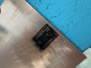
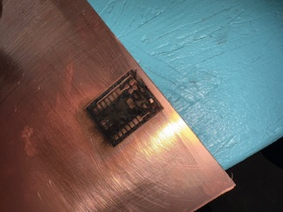
I was hoping to be able to work with the actual board for this week, but unfortunately out XTool machine was not working the way that we wanted it to, so my attempts to create a board didn’t work. If they had, then I would have been able to run the same code seen later (in Wokwi) through the actual board. Instead I will show the steps to run the code, and then also the successful code execution in Wokwi.
-
Read the Data Sheet for the RP2040


- Install Arduino IDE onto local machine
- Install the proper libraries for the Seeed Xiao RP2024
- Search the board manager and find the RP2024
- Here, you would normally be able to (and I was hoping to) connect to the board through Arduino IDE and a breadboard. Instead, I will be running the code through Wokwi to simulate the execution on a Raspberry Pi Pico board using the RP2024
-
My lab has a limited selection of microcontrollers, restricting comparison options.
Currently available microcontrollers: Seeed Studio XIAO RP2040 and Seeed Studio XIAO SAMD21.
Both microcontrollers look similar but have key differences.
To compare them, I read their datasheets, identified specifications, and created a comparison table.
RP 2040 SAMD 21 Architecture ARM ARM SRAM 264 KB 32 KB OS Not Applicable Not Applicable Clock Speed 133 MHz 48 MHz Number of Cores 2 Not Applicable Flash 2MB 256KB Compatible Languages Micro/Circuit Python, Arduino Micro/Circuit Python, Arduino Pins - 11 Digital
- 4 Analog
- 11 PWM
- 1 I2C
- 1 UART
- 1 SPI
- 1 SWD
- 11 Digital
- 11 Analog
- 10 PWM
- 1 DAC
- 1 I2C
- 1 UART
- 1 SPI
- 1 SWD
Below are two snippets of code that I used and tested to get an LED to flash both quickly and slowly:

After experimenting with an LED, I moved on to test the capabilities of an LCD screen using the LiquidCrystal.h library. Below shows a snippet of code and exectution of flashing text on an LCD screen using Pi Pico through Wokwi:

For the group assignment:
One of the things that could have been improved for this week would have been to be able to run my board using an actual microcontroller and a breadboard. I was planning to do this to be ahead on assignments for the next two weeks as well, but unfortunately, I was not able to get our XTool F1 to work to laser engrave a PCB (and I do not have milling experience yet), so I was not able to make that happen.
Another dramatic that could have been made to my process this week would have been to be better equipped to read a data sheet. I felt really underprepared in reading the data sheet, so it took me much much longer than anticipated in order to complete skimming it, while also gleaming any kind of information from it.


- Prepare more time for any reading/research for weekly assignments
- I enjoy the process of using the XTool, but I need to make sure that it works to fabricate a PCB for the final project