Computer Controlled Cutting
Am I missing an eyebrow? ― Adam Savage
ZB FAB Academy W03 Planning
Plan/Dates:
- Thursday 2/6/25 EOD:
- Safety Training/Group Assignment: understand settings on laser inc. focus, power, speed, rate, kerf, joint clearance ,and types
- Friday 2/7/25 EOD:
- Use design from W02 to cut on Vinylcutter
- Begin parametric CAD design process for press-fit kit
- Saturday 2/8/25 EOD:
- N/A
- Sunday 2/9/25 EOD:
- N/A
- Monday 2/10/25 EOD:
- In-work: Finish CADing process and laser cut the press-fit kit
- Out-of-work: Start documentation finalization (i.e. uploading pictures, finalizing website design, etc.)
- Try to finish as much as possible by 16:00 EST for mtg. time
- Tuesday 2/11/25 EOD:
- Catch-up/documentation finalization day
Process This Week:
Tasks This Week:
Group assignments:
Individual assignments:
Below, I walk through some of the notes/screenshots that I have from my work this week and explain my thought process as I was completing my assignments.
Process From This Week:
- READ SAFETY INFORMATION
- Air Extraction: Depending on the material being processed, you may need to switch on the air extraction system. This is crucial for removing fumes and preventing the accumulation of smoke, especially when working with materials like wood or acrylic. Always follow safety guidelines and use appropriate ventilation.
- Protective Gear: Wear appropriate safety gear, such as safety glasses, to protect your eyes from laser radiation. Ensure that the laser cutter is operated in a well-ventilated area to minimize exposure to fumes.
- Open Onshape
- Create a new document
- Create variable for parametric dimensions. A driven or parametric dimension is a reference parameter that reports a measurement value for the associated geometry. It does not define or drive the geometry and therefore cannot be directly edited.
- Select sketch plane
- Select corner rectangle tool to being creating base of box
- Select corner rectangle tool again to start making box joint tabs
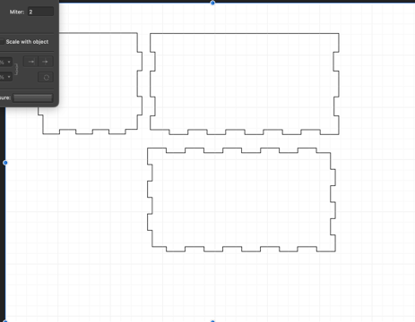
- Dimension length and height of box and tabs using variables established at the beginning.
- Repeat for each side of the box
- After all dimensions are set, click finish sketch and then extrude to account for Kerf
- Assemble parts to make sure box fits together properly
- Create drawing file of parts to export to laser cutter
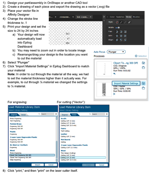
- Open Affinity Designer and import drawing file
- In Affinity Designer edit line thikness to make sure that they will read as vectors in the Epilog laser cutter.
Lines must have a thickness of .01pt in order to be read as vectors.

- Follow the following steps for using the Epilog Laser Cutter
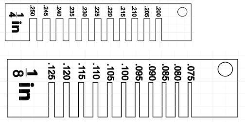
- Make Sure to Adjust for the Kerf


Here is a video of the laser in action
Improvements/Helpful Hints:
- One of the most important improvements that I would make to my process from this week would be understanding that creating when exporting the drawing files from Affinity Designer to the printer, you need to make sure that the size does not get changed. As you can see in the video above, there is a large size discrepency between how it looks in the laser cutter and the SVG file in Affinity.
- Another big improvement that could be made for the work this week is that you should make sure that you actually follow all of the safety protocols for the Lab!! Using the Epilog, I had a small issue where my Materials caught on fire. Although there was not a catastrophic event, I just needed to make sure the air ventilation was on; in this particular case, I had turned on the air filter, but not the actual air compressor.