CAD
Computers are magnificent tools for the realization of our dreams, but no machine can
replace the human spark of spirit, compassion, love, and understanding. — Louis V. Gerstner, Jr.
ZB FAB Academy W02 Planning
Plan/Dates:
- Thursday 1/30/25 EOD:
- Work on 3D model of final project prototype (FPP) shell
- Friday 1/31/25 EOD:
- Begin work in Affinity Designer, learning basics of Vector/Raster
- Saturday 2/1/25 EOD:
- Finalize 3D model of FPP shell
- Monday 2/3/25 EOD:
- Finalize two designs in Affinity Designer
- Documentation catch up time
- Tuesday 2/4/25 EOD:
- Finish Documentation by 14:00 EST
Process This Week:
Tasks This Week:
Below, I walk through some of the notes/screenshots that I have from my work this week and explain my thought process as I was completing my assignments. During week 2 I approached two seperate parts of my final project (at least in the form that it exists in right now). I started by first designing a first draft CAD model of the shell for my midi controller. To start this process, I practiced some basic skills in Onshape, including making several mistakes (see below) that helped to inform my later progress.
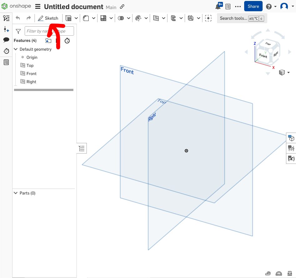
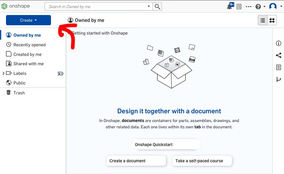
- Create a New Document in OnShape
-
Define a Sketch Plane and begin drawing using constraints to keep nicely defined and organized dimensions.
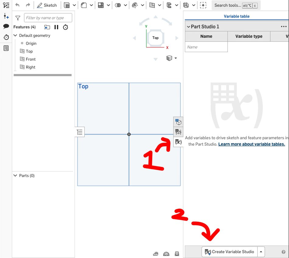
-
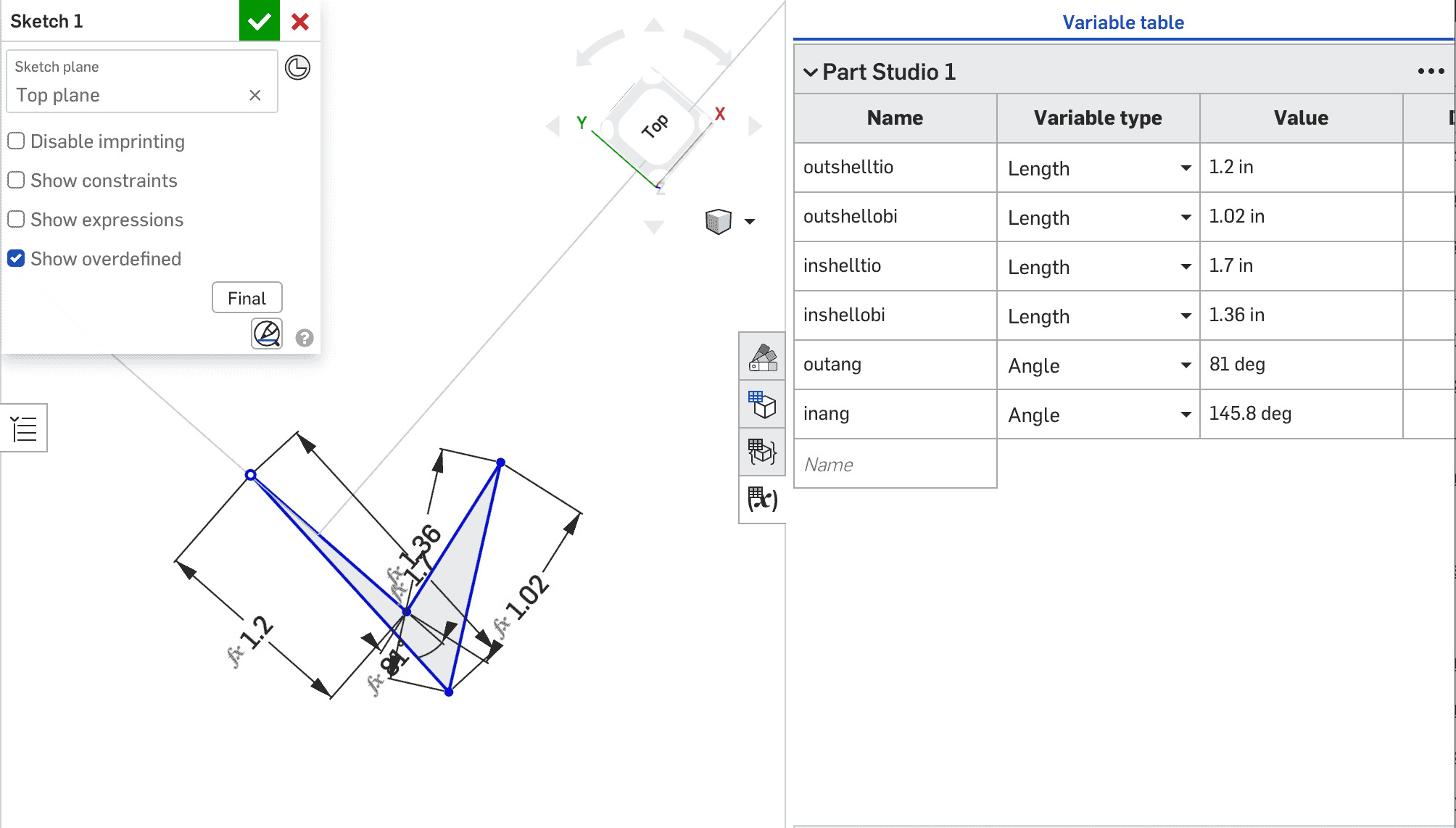
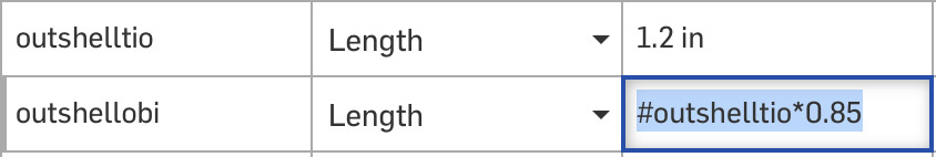
Use parametric design (in OnShape Variable Tables) to keep every dimension relative, so that adjusting the scale of your
design becomes much easier
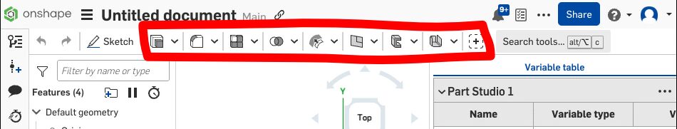
-
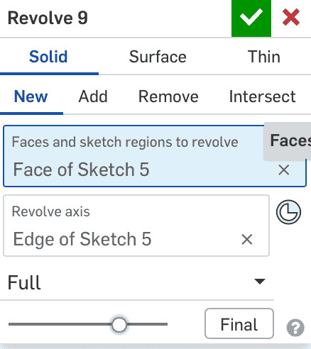
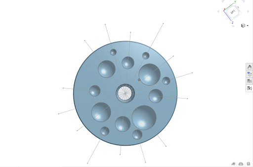
Create 3 Dimensionality by extruding, revolving, etc. using OnShape's different tools.
- In my case, here, I used both Revolves and Extrudes to create a large flat surface and some sphere's for a later boolean removal
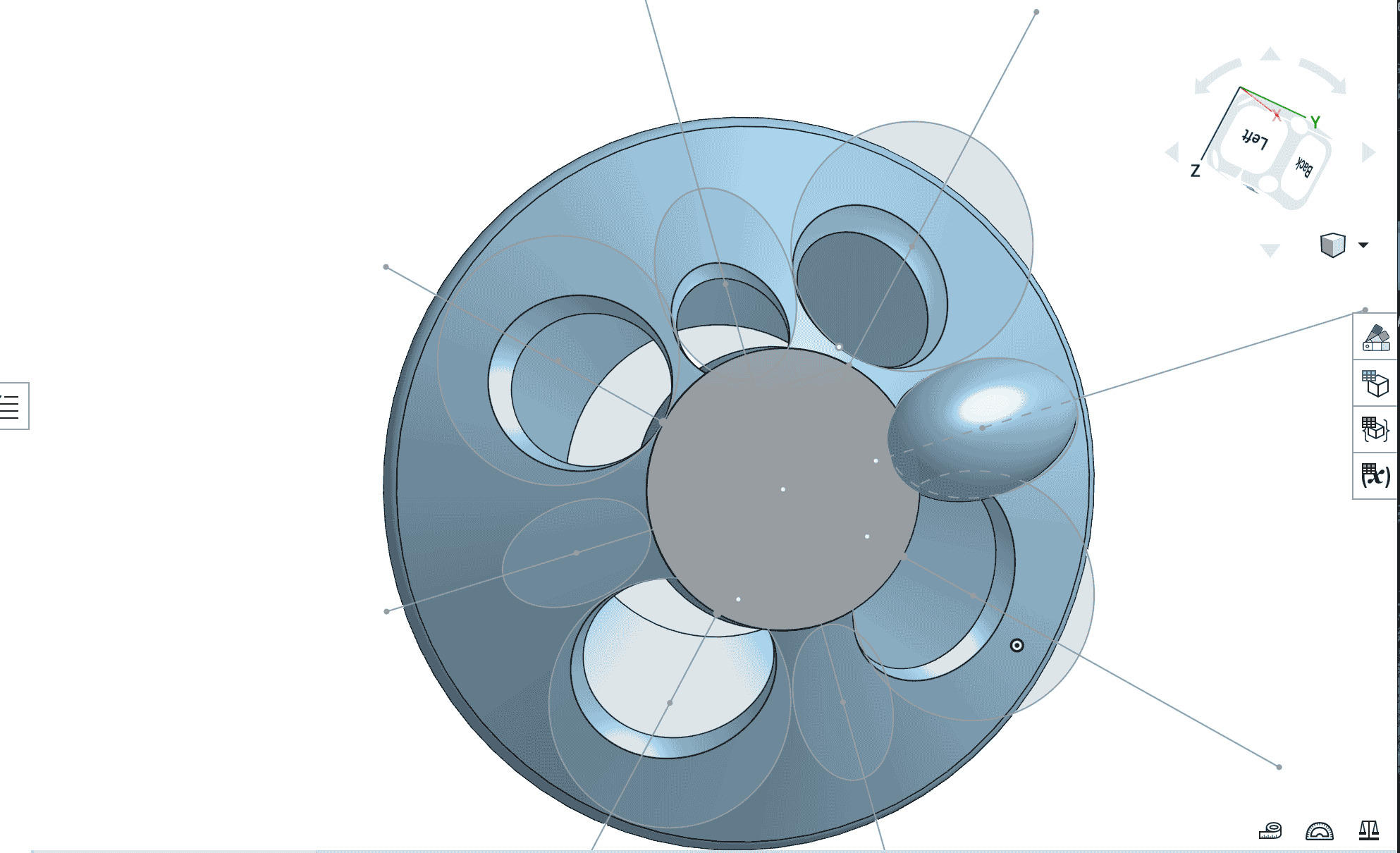
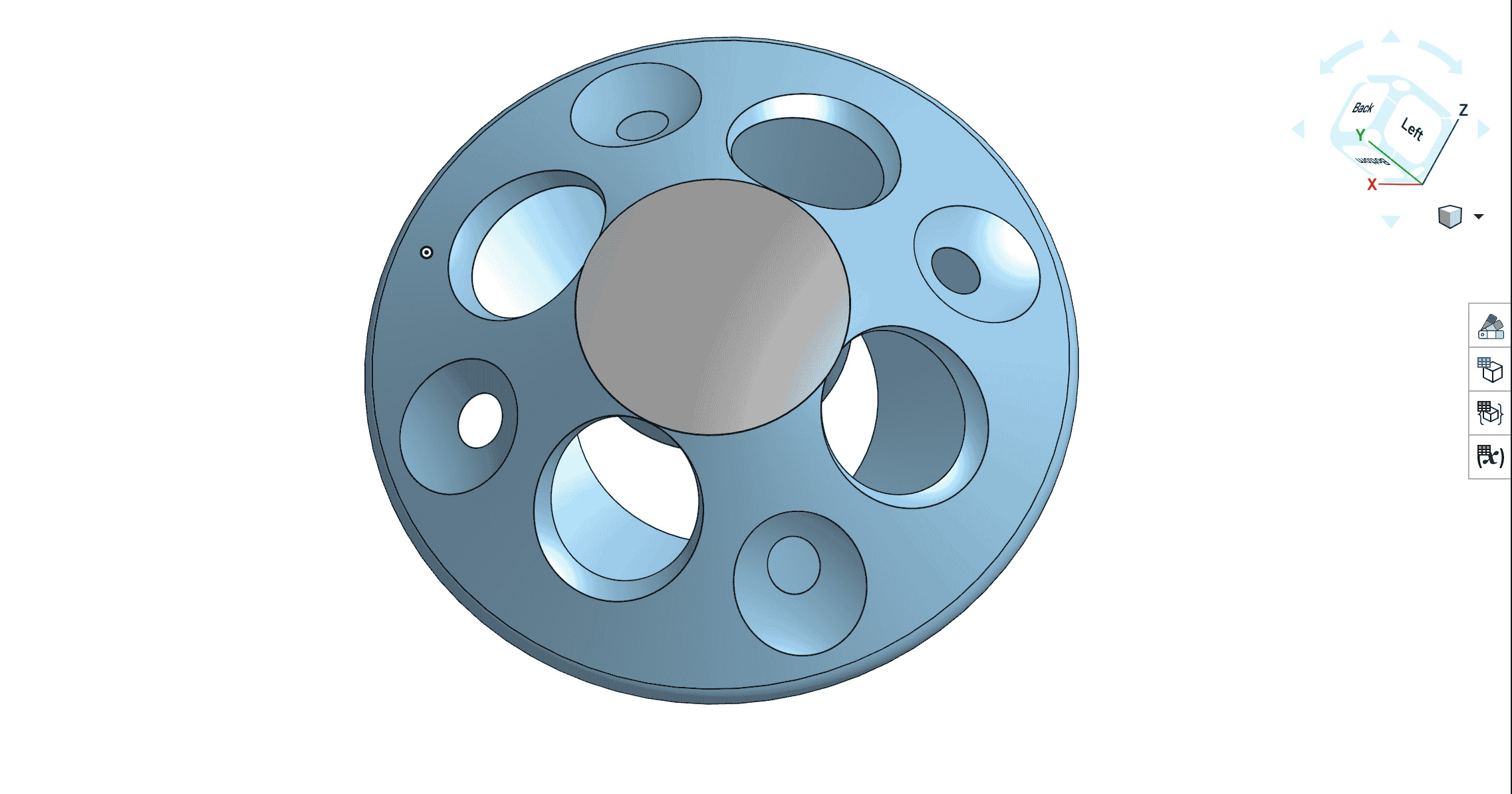
- Use Bools to either add or remove from what already exists to refine the shape of your design. My final design looked something like this:
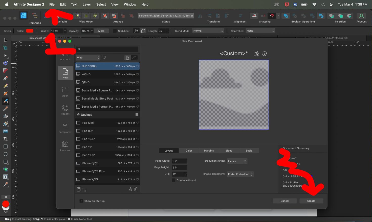
- For the Vector art, open Affinity Design and create a new file
- Select one of the tools shown here to create some kind of design
-
Process and export as an SVG or Rasterize and export
-
Here I created a starting design for my final project, which could be engraved onto the side of the final project shell
- There are two notes here: First, I think that I had a leg up in terms of learning a new vector art program because of my previous experiences. But more importantly, two, I learned the difference between a Raster (i.e. essentially pixel) vs. a Vector (i.e. a mathematical model).
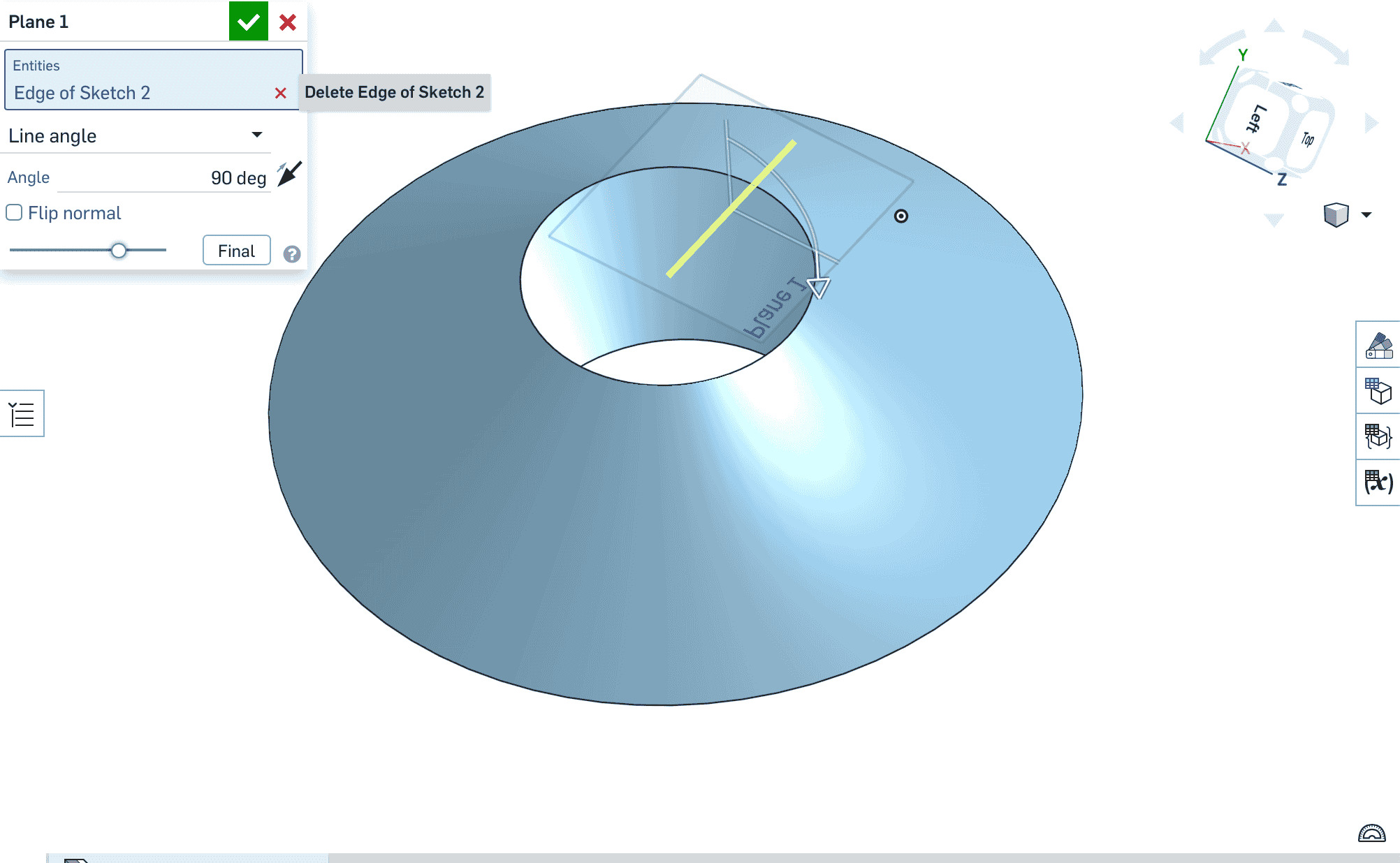
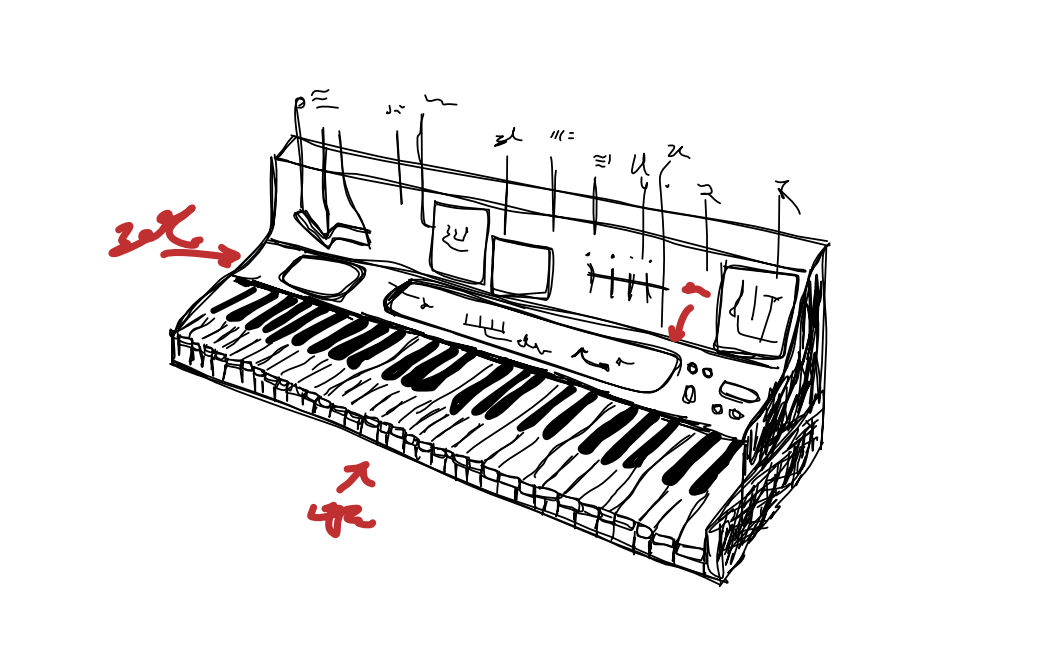
- In this week, two of the big problems that I faced were figuring out how to create 1. a plane on top of an already established sketch in Onshape and 2. how to design more effectively through variables (i.e. parametric design). Trial and error mostly solved both issues. However, two of the very helpful things that I learned along the way that I hope to implement moving forward, is that starting and planning ahead in small steps before implementing in Onshape/your CAD program is very (very) helpful. By taking smaller steps, each one becomes more manageable to commit to in Onshape and is further eased if there are physical drawings/writing to help aid this process (see here for my arbitrary notes/drawings for the week). The second major MAJOR!!!! piece of advice to myself and to others, is to just %&!@*& put your documentation into your website as you go. The first week was infinitely easier because I followed that. Instead now, I am trying to play catch up.
- Although I had some experience using CAD software before entering the class, my skills were limited and I had mostly used simple programs like tinkerCAD. Moving to a more advanced program like Onshape, I had some difficulties getting adjusted. One of the most important areas for that was using constraints.
- In my first iteration of parametric design, I made a minor, but instructive, mistake in trying to overdefine each of the angle and length measurements of my project instead of having one that remains constant.
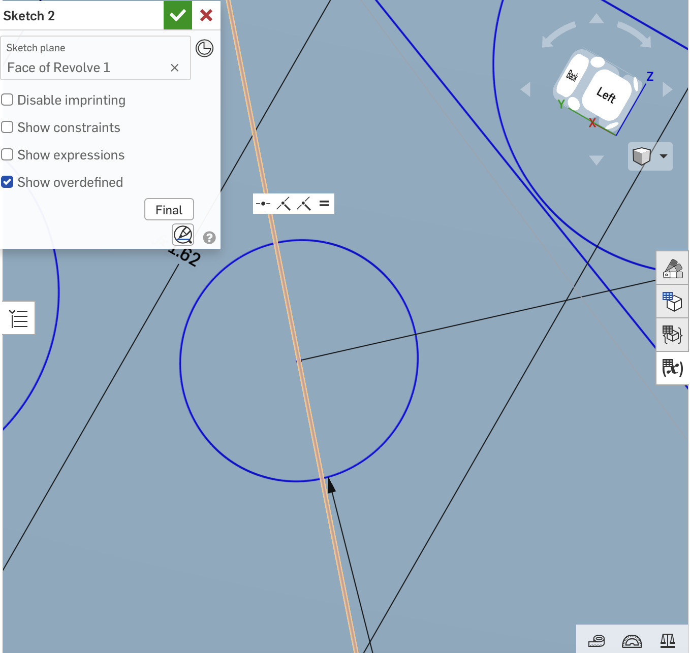
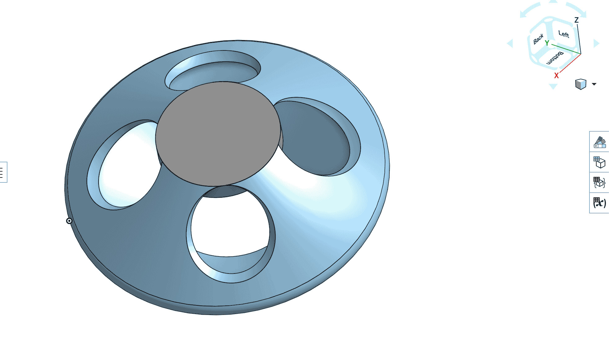
- In starting, I wanted to have a slanted surface on which to play, but ran into several problems creating consistent buttons to place on top. In using revolves and then booleans to remove material from the final form, I was able to create cutouts, but a major problem that presented itself: I was not able to keep them as consistent as I wanted to. In the next picture, you can see that in creating a flat surface, I was able to create better defined relationships between each of the cutouts for the holes for my final project shell.
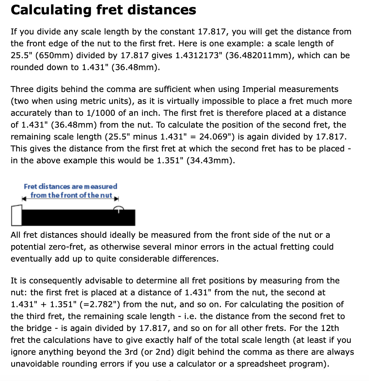
- Specifically, I used the method for determining the fret sizes for a guitar to help determine a "fret" (read here as button) size for my midi controller. Because I grew up playing the guitar, I wanted to use a consistent scale "length" that mixes the feel between a guitar and a handpan - in order to maximize playability, comfort, and intuitivity. In this final version, there are button cutouts for each of the chromatic notes of Western style music (i.e. it is not microtonal). In creating this, I developed a function that determined the size of each button given the size of a desired first button and the relative size of the final button. This final (for this week) model of the handpan/Synestone gives me a good starting point to work from when we visit 3D printing later. I have created this model in a small scale, and using the parametric design, I should easily be able to scale it up to its full size when necessary. I plan, for now, to use plastic 3D print filament (PLA) to print this outer shell, and will hope to do some rapid prototyping as we approach 3D printing in the schedule.
- I think that I had a leg up in terms of learning a new vector art program because of my previous experiences. But one important thing that I learned was the difference between a Raster (i.e. essentially pixel) vs. a Vector (i.e. a mathematical model)
Research Materials/Links