Goal: Add an output device to a microcontroller board you’ve designed,
and program it to do something
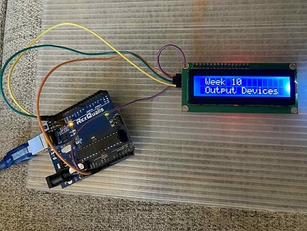
Added an 16x2 LCD screen with I2C adapter
I will be connecting to a 16x2 lcd display with I2C (4-pin) module.
I have this model as well a model that doesn't have the I2C adapter.
There is far more documentation and information on helping users get
started with the model that has an I2C connected to it, compared to
just a standalone version. This I2C adapter can be soldered to the lcd
display to make connecting it to microcontroller boards much simpler
because this adapter has 4 pins that needs to be connected to the
microcontroller board. Without this adapter, you would need have 16
pins to connect/disconnect for projects & testing. Here is a little
information on this lcd display.
Here is how the 16 original pins are used
8 Data Pins (D0-D7): These pins are used to transmit data to the LCD for display.
2 Power Supply Pins: These provide the LCD with the necessary voltage.
1 Contrast Control Pin (VEE): This pin adjusts the contrast of the display.
3 Control Pins (RS, RW, E): These pins are used for controlling the LCD's operation.
2 Backlight Pins (optional): Some LCDs have two additional pins for controlling the backlight.
What can this LCD do ?
Part of the assignment was to program an output device to do something.
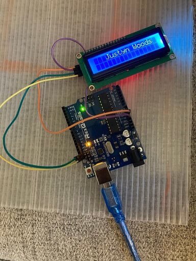
In the picture below I programmed the lcd screen to display my first and
last name on the first line of the lcd display. Up to 16 characters per
line can be displayed. A total of 2 lines can be displayed at one time.
This allows for a maximum of up to 32 total characters on screen at a time.
In order to create pull this off, all I needed were a few simple things
such as an Arduino Uno R3 board, 16x2 lcd display with I2C adapter & wires.
The connection is pretty straight forward. The 'VCC' pin on the lcd display
connects to the vin/5v pin of the Arduino, the GND pin on the lcd connects to the
GND pin on the Arduino, SDA & SDL pins from lcd display connects to the same
name counterpart pins on the Arduino.
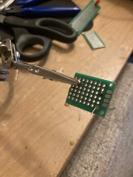
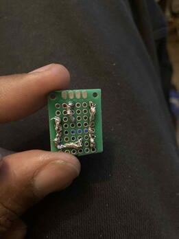
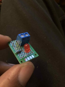
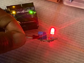
I soldered an LED testing board
This is an LED board that I soldered to test with an Arduino microntroller board.
The soldering job is rough...lol. But it worked an I was able to connect it to test.
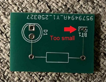
I recently designed an LED board in Kicad, but I decided not to go with that board.
I actually set the wrong size jumper/connections for power to that board, and I dont
have any connectors in my inventory to go with it so that board is put away fo now.
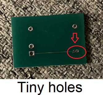
So using creating led sensor board from a prototype board was simple. Rather than
Soldering and snipping wire on the underside of the board where the connections
are smaller and neat, compared to the image in the example below. I'm using the
solder in this example the way traces work in an actual pcb. Once I get a little
tighter with my THT (Through Hole Technology) soldering I will move on to SMD an even
cleaner type of solering which is also far more difficult. SMD simply stands for
(Surface Mount Design). Which requires smaller components that dont have wires
or stems that go through holes. SMD components are typically flat on their underside
or will have pins that are countured so that they can lay flat on a surface and be
soldered that way. SMD soldering is also more difficult to see the smaller parts and
the soldering technique that you will use will differ from you THT technque.
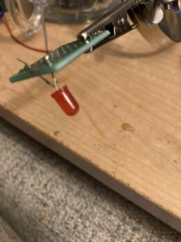
This was a way to practice and improve on my soldering skills and have a sensor that
that I can use. Here are a few pictures that were taken during the process.
Here's how I made the led board in kicad
To begin, start the Kicad program.
- Once the program is open click in the top left corner and select 'File"
- Now select New Project to begin a new project.
- Choose a location to save your work and also choose a relevant filename.
- Create a Schematic file by clicking the Schema button in the toolbar or by
clicking on the schematics file on the left side of the screen.
Placing Components
- We will begin with placing icons that will represent the real world components.
- Click on the 'Place Component' icon on the right side of the screen, then click anywhere
on the screen to open up the component library.
- Allow the component library some time to load, it's not often an automatic thing.
- Once the component library has loaded you can begin typing the name of the component
that you would like to use inside the blank textbox.
- As you type, lists will begin to populate and display a large number of components
as well as a picture diagram of the part.
- We will add a resistor by typing the letter 'r' or typing out the entire word 'resistor'.
- A list will populate and the resistor will now become a part of this list.
- Double-click on the resistor selection, it uses an 'R' as a secondary identification.
- Now click anywhere on the screen to place the resistor on the grid.
- You can move the component after placing it by clicking on it and pressing the letter "M" key.
Now when you move your mouse, you are moving the icon as well. Click again to place
the icon in the desired location.
- You can rotate the icon by clicking on it and and pressing the letter "R", and the icon will
rotate 90 degrees.
- To change the value of a component, press the letter "V" or double click it and type in
the new value in the textbox assigned with Value.
- We will set the resistor value to 470, this will allow smaller current/flow of electricity
to pass to the led which would normally destory the led. But the resistor is providing
resistance against the flow of electricity and allowing a feasible amount that wont allow the LED to be damaged.
- Now lets place an LED on our grid that will illuminate when connected to a power source.
- Click on the 'Place Component' icon, and click on the grid to bring up the component library.
- In the textbox, delete any existing text. Now type LED to bring up the LED. Select this option and click anywhere
on the grid to place it.
- Now lets add a battery by clicking on the 'Place Component" icon on the ribbon, located on the right side of the screen.
- Click anywhere on the screen to open the component library. Once opened type in the word battery and double click it
when it appears as a selectable component.
- Click the letter "V" or double click on the icon to access option to modify the value.
- We will assign the value of the battery to 9V.
- Lets align the components so that they can be easily wired in a non conflicting manner.
- Set the resistor as it is in a typical rectangle form (long ways left to right) by clicking it once and then pressing
the "R" button to rotate it.
Click on the LED and make sure that the number 2 side is facing up and the number 1 side is facing down. With the
2 arrows in the icon drawing are pointing down.
- Each of these icons have 2 terminals (1 on each end). This is where the wires connect components to one another.
- To place a wire you can press the "W" button.
- Another way is to click on the terminal end located at the + side of the battery icon.
- Connect this wire to the resistor icon by selecting the terminal on the left side of the resistor icon.
- Add a 2nd wire to connect the right terminal of the resistor to the #2 side of the LED
- Now create a wire to connect the #1 terminal of the LED to the - terminal on the battery.
- This completes the circuit.
- Now that we have our components placed, we will now "annotate" so that the components are assigned a number to
identify them within the project.
- Click on the 'Tools' option at the top of the screen and select annotate when menu pops up, select 'annotate'.
If a warning pops up, select 'yes' or 'ok' to proceed.
Assign Footprints
- Go to tools and select Assign Component footprints.
- Make the selection and wait a short while for the next menu to load.
- Now we will define the footprint (attributes) that we want for each component.
- In the middle panel on your screen is a list of the components that you have
selected to use for this project. To assign footnotes to the components you
must click on the component in the middle panel.
- Now choose a category from the left panel. We will look for a pinheader connector
as a battery/connection mechanism to receive an electric current to power the board.
- Now take a look in the right panel to select a footprint that will be assigned.
- You can see what the footprint looks like, by clicking on 'view selected footprint' in the
toolbar at the top of the screen.
- We will use the pinheader connector called pin_header_Straight_2x01_pitch 2.54 (pitch may
not shot up in name, its okay as long as you see 2x01 and 2.54 in the filename.
- Double click on the footprint to assign it.
- Lets assign a footprint for the LED.
- Choose LED library and select the 5mm footprint
- Lets now select a footprint for the resistor.
- Click on the resistor in the middle panel, and select 'Resistor_THT' from the left panel
- In the right panel, scroll up or down until you reach the footprint that fits the following
description = R_Axial_DINO207 p15.25mm_horizontal
- Double click this footprint upon finding it
- You can now close the assign footprint window. You will return to the schematic view
- You can run a quick check to make sure everything is working properly so far by performing an
electrical rules check'. Select this option in the ribbon at the top of the screen.
- Click run, wait after check is finished then click close.
- You can generate a check list by clicking in the ribbon 'generate checklist' click generate then save the file.
- Now click on the pcb view icon (usually a green icon) in the top ribbon
- You will now be taken to a new screen to add last touches for the board
- You will need to select update PCB from schematic icon, this will bring your schematic design in to be wired and
finished. Press ok to close this menu and return to screen so that you can place your schematic
- Click anywhere on the screen to place your footprints.
- You can click on your component and press "M" to move them to your desired located.
- Arrange the components in a way that the white line that is connecting them can connect easily and keep components
somewhat close in proximity.
- Now draw wires between components by click on the icon 'route single trax'
- Click on the component terminals to create a wire that will connect to the next component.
- Connect the #1 terminal of the pinheader to the #2 terminal of the resistor
- Connect the #1 terminalof the resistor to the #2 terminal of the LED
- Now connect the #1 terminal of the LED to the #2 terminal of the pinheader connection component.
- You can choose different layers to place wires or write/draw on by selecting the layer of your choice. Remember
that these layers serve different purposes.
- To make the outline for your board shape you must select the 'edge cuts' layer
- Now select graphic line or polygon tool in the toolbar to create and form a shape for your board
- Draw the board outline and double click when it is finished. Zoom in to make sure all lines are connected
of the board outline.
- You can now see your board in 3d. Go to 'view' in top ribbon selection and click on
3d viewer to see and move your board around in 3d space
- Save your project by clicking on the floppy disk icon in the top of the screen ribbon.
- Now go to the file menu and select fabrication outputs, and select gerber
- Select generate drill files, then select plot.
Project is finished and can be processed to be sent out for printing.