Week 8: Electronics Production
JLpcb process and testing of microcontroller
On this page I will discuss the rp2040 xaio board that I designed in Kicad.
After completing the design in Kicad I uploaded the files to JLpcb and within
10 days I received my board that was ready to connect to the rp2040 via solder.
The process was easy and pretty straighforward. I uploaded the gerber files,
selected the color as well as how many boards that I wanted to receive and
that was pretty much it. That process was alot simpler then I thought it would be.
Uploaded to JLCPCB

Ordered finish board from JLPCB
Board after soldering sockets for inputs
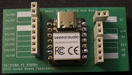
Newer board ready for testing
Here is the project file from Kicad
I uploaded the original file and it's now downloadable
Custom Xaio BoardSimple blink test of led & board
Arduino Ide Code for blink test
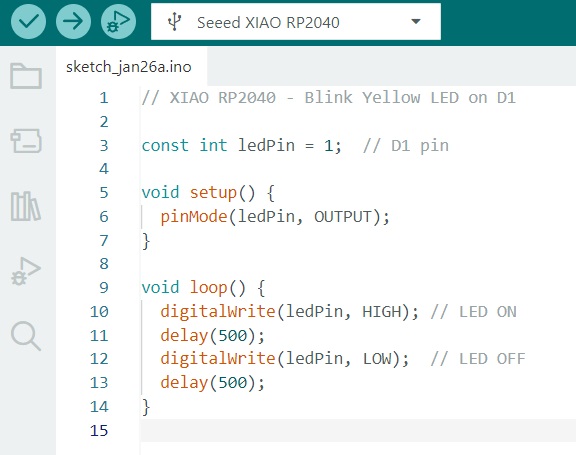
blink test screenshot