7. Computer Controlled Machining
Make (design+mill+assemble) something big
CNC Routing Workflow DocumentationFor Week 7 I explored large-scale subtractive manufacturing using a Next Wave SHARK HD520
CNC routing machine located at a local woodworking shop.
The purpose of this assignment was to:
- learn CNC path cutting workflows
- understand subtractive manufacturing methods
- explore CNC milling operations
- gain experience with CNC software workflows
- observe how digital toolpaths translate into physical material removal
This assignment also helped develop a better understanding of efficient CNC fabrication
workflows and machine operation procedures.
Project Concept and Design Planning
The original concept for this project was the development of a layered shelf system designed
to contain hidden LED lighting underneath the shelving structure.
The shelf was intended to become part of a larger-scale fabrication project involving:
- layered structural components
- concealed electronics
- hidden wire routing
- integrated LED illumination
As the design process continued, the overall project was temporarily placed on hold due to:> - increasing material cost
- expanded fabrication requirements
- workflow planning limitations
- late-stage design changes and implementation adjustments
Even though the larger project was paused, the CNC-machined shelf component remained useful
for learning CNC routing operations and machining workflows.
Design Software Workflow
The initial design work was created in Cinema 4D.
Cinema 4D was used to:
- model the shelf structure
- create routed internal cavities
- prepare geometry for subtractive machining
- experiment with dimensional layout
The completed 3D model was then exported as an:
.STL file
The STL file was opened and prepared for machining using CNC routing software
associated with the SHARK HD4 machine. The design dimensions were adjusted to
fit a large available wood board that was suitable for the machining process.
Material and Machining Goals
The workpiece began as a solid wood slab approximately:
1 3/8 inch thick
One of the major machining goals was to create recessed routed channels deep enough to:
- hide wiring
- contain electronics
- support hidden LED lighting systems
The internal routed dimensions were approximately:
4 mm deep
11 mm wide
These recessed routing channels were designed into the underside of the shelf structure.
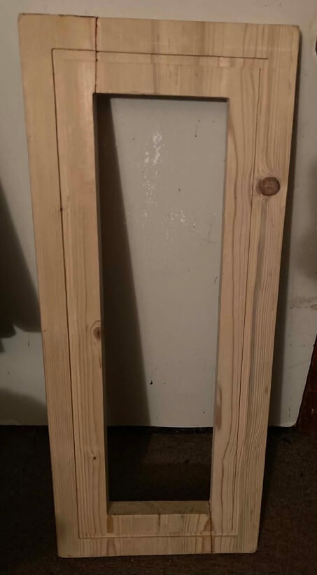
The final machined object became a large rectangular frame-like component with:
- routed internal cavities
- open interior regions
- recessed channels
- profile-cut edges
Tooling and CNC Machining Operations
Two router bit sizes were used during the machining process:
1/8 inch bit
1/4 inch bit
The smaller bit allowed tighter routing detail and narrower channels, while the larger bit
improved material removal efficiency during larger routing operations.
Unlike laser cutters which remove material using beam width and thermal energy,
CNC routers remove material based on the physical diameter of the cutting tool.
In CNC machining, the effective cutting width is determined by the router
bit diameter. This affects:
- dimensional accuracy
- internal corner geometry
- routed channel width
- edge detail
Because rotary cutting bits are circular:
- internal corners become rounded
- sharp inside corners require additional toolpath compensation methods such as dogbones
This assignment helped demonstrate how tool diameter directly affects machining
geometry and final part dimensions.
Machine Configuration and Operation
The CNC router was configured using the Next Wave CNC software interface.
During machining:
machine speed was set to 10
machine power was set to 65
The wood stock was securely mounted before machining began to prevent movement during routing operations.
After setup and toolpath preparation:
- the machine origin points were established
- cutting operations were started
- the CNC router automatically followed programmed toolpaths
The machining process required multiple cutting passes to gradually remove material while reducing
strain on the tooling and improving machining stability.
The overall cutting process took several hours to complete due to:
- material thickness
- routed depth
- multiple machining passes
- large workpiece dimensions
Machine Monitoring and Safety Features
During operation, compressed air was used to clear sawdust buildup from the cutting
region and improve visibility of the routing paths.
One feature I observed on the SHARK HD4 machine was a built-in safety behavior involving the touchscreen interface.
While the CNC router was actively machining, the mini LCD touchscreen controls became locked during operation.
This appeared to function as a safety feature designed to:
- reduce accidental input
- prevent operational interruption
- protect active machining processes
This highlighted the importance of machine safety and controlled workflow management during CNC machining operations.
Machining Observations and Workflow Development
Throughout the assignment I observed several important CNC fabrication concepts:
- subtractive manufacturing removes material gradually through repeated passes
- larger routing operations require significant machining time
- tool diameter affects edge detail and corner geometry
- proper workholding is critical during machining
- sawdust accumulation can affect visibility during operation
- different bit sizes serve different fabrication purposes
This assignment also improved understanding of:
- CNC toolpath planning
- workflow organization
- CAD-to-machine fabrication pipelines
- routing depth control
- material removal strategies
- machining preparation procedures
Fabrication Outcome
The CNC router successfully transformed a solid wood slab into a routed structural component
using computer-controlled machining methods.
The completed part demonstrated:
- profile cutting
- routed channels
- recessed cavities
- controlled-depth machining
- subtractive fabrication workflows
- multi-tool CNC routing operations
The machining process successfully created routed internal pathways intended for future
hidden electronics and LED integration concepts.
Project Evaluation
- digital 3D models can be converted into physical machined objects
- toolpaths guide automated material removal
- router bit geometry affects physical outcomes
- multiple machining passes improve stability and cut quality
The assignment also emphasized the importance of:
- workflow planning
- machine setup
- material preparation
- safety awareness
- iterative fabrication development
This CNC machining process helped strengthen understanding of computer-controlled manufacturing
and how subtractive fabrication techniques can be applied to larger structural and
functional design projects.
Gallery
Here are a few pictures in the Woodshop
Although compressed air could have been used to rapidly clear
debris, doing so inside the enclosed workspace would have created a
much larger cleanup situation due to airborne sawdust distribution.
Instead, brushing debris away during machining and sweeping the
workspace afterward proved to be a cleaner and more
controlled workflow approach.
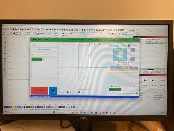
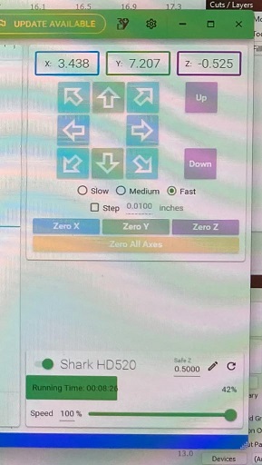
The Next Wave CNC software provided a live visual representation
of the active toolpath during machining. This made it easier to monitor
routing progress, confirm cutting direction, and observe how the machine
translated digital paths into physical material removal operations.
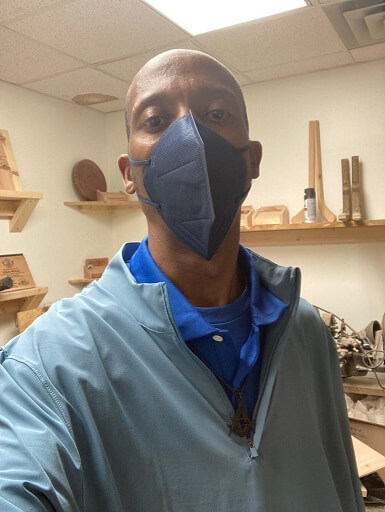
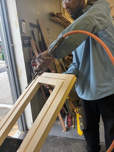
During this assignment I used a Next Wave SHARK HD520 CNC routing
machine at a local woodworking shop. While operating around the machine
I focused heavily on safety due to the large amount of airborne sawdust
and active moving machinery. I wore a protective face mask throughout the
machining process to reduce inhalation of fine wood particles generated
during routing operations.
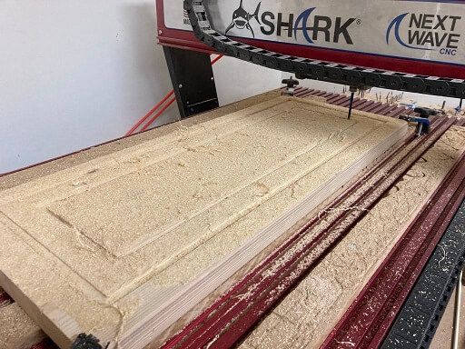
As machining progressed, large amounts of sawdust accumulated directly
on top of the workpiece and inside the routed channels. To maintain visibility
of the cutting area, I periodically used a soft-bristle shop brush to carefully
remove sawdust buildup whenever the router head was positioned far enough away
to avoid any danger or interference with the active machining process.
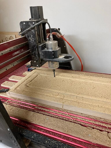
This image captures another angle of the CNC machining process while the
SHARK HD520 router was actively performing routing operations. Multiple viewing
angles helped document machine movement, material positioning, and overall
fabrication workflow during cutting.
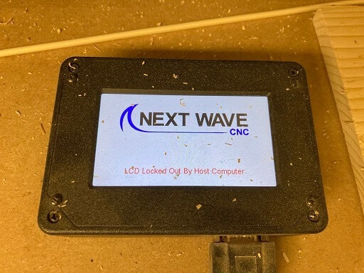
While the CNC router was actively operating, the LCD touchscreen controls
became locked. This appeared to be an intentional safety feature designed to
prevent accidental input or interruption during active machining operations.
Safety-focused design features like this are important when working with
large automated fabrication equipment.
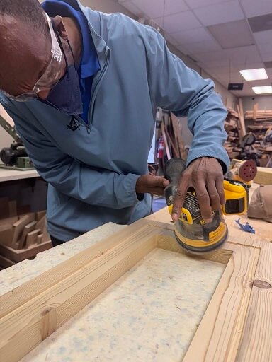
The machining process also required post-processing and surface
cleanup after routing was completed. In one of the documented images
I am using a power sander to smooth rough surfaces and refine the
routed edges of the machined wood component. Sanding helped improve
the overall surface finish while removing splinters, rough tool
marks, and minor imperfections left behind from the CNC
routing process.
One important observation during machining was how quickly sawdust
could obscure routed details and active cutting paths. Frequent cleaning
of the work surface improved visibility and made it easier to monitor
routing progress, cutting depth, and overall machining consistency
throughout the fabrication process.
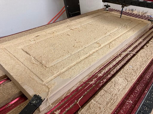
This image shows both routed toolpaths successfully completed within
the workpiece. The CNC router maintained consistent cutting depth and
alignment throughout the machining process while following the programmed
digital toolpaths.
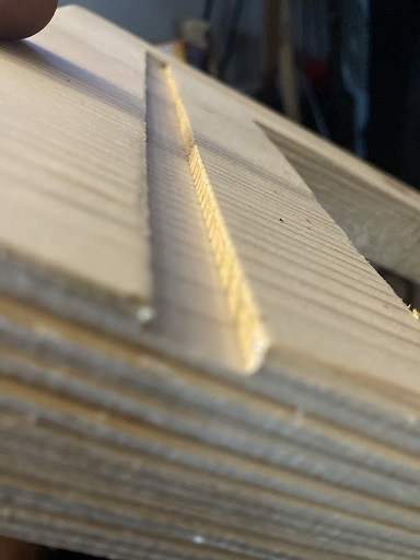
This close-up image highlights the quality of the routed edge produced
by the CNC machine. The cut demonstrated smooth routing behavior, controlled
depth, and clean material removal with minimal visible tear-out along the
machined surface.
After machining was completed, the workpiece was moved from the CNC room
into the main workshop cleanup area. Compressed air was then used to remove
excess sawdust and debris from routed channels, corners, and surface areas
before additional finishing work began.
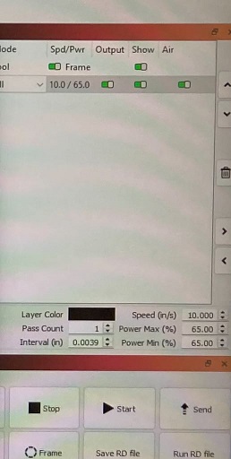
The machining process used machine settings configured within the Next Wave
CNC software environment. During operation, the speed setting was configured to
10 while the machine power setting was configured to 65 in order to maintain
stable routing performance throughout the cutting process.
Large CNC routing operations can require significant machining time due to
multiple cutting passes and gradual material removal strategies. During this
stage of the workflow, the machine continued executing programmed toolpaths
while routing the remaining sections of the design.
Hear are a few videos
Noise sensitivity warning....volume is loud !!!This video demonstrates the CNC router creating recessed internal
routing paths intended for future LED lighting integration. The routed channel
was designed to provide space for hidden wiring and lighting components underneath
the shelf structure while maintaining a cleaner external appearance.
This close-up video captures the CNC router performing an interior
profile cut along the mid-center of the workpiece. The footage highlights the
precision of the automated toolpath movement and shows how the router gradually
removes material while maintaining consistent edge alignment.
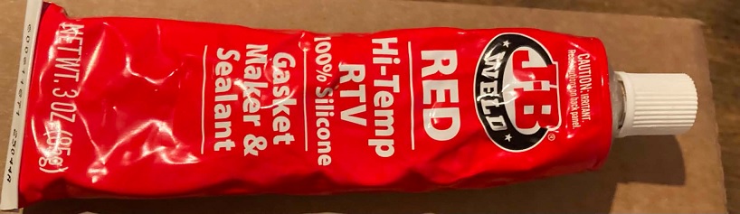
I dropped it !
I can't conclude this week without telling the full story behind this frame.
I dropped this frame within 35 minutes of it being finished. It split on the
short sides. The frame basically cracked in half...my heart sank as I looked
at this frame on the ground in 2 pieces. I waa able to repair it. I used some
jb weld at the broken joints, allowed a day or 2 for drying then shaved of
excess dry weld leftover
Hero Shot
Although it did break, I'm glad that it was able to be repaired and is very
strong. I have held it at strange angles to test the holding power. The frame
is solid and ready to be used in a project.
The frame rendered in 3D
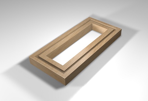
Here is the .stl file
Download the .stl