6. Electronics Design
Group assignment:
Use the test equipment in your lab to observe the operation of a microcontroller circuit board(as a minimum, you should demonstrate the use of a multimeter and oscilloscope)
Document your work on the group work page and reflect what you learned on your individual page
Individual assignment:
Use an EDA tool to design a development board that uses parts from the inventory to interactand communicate with an embedded microcontroller
What I've learned in Electronics Design
I learned how to create a (PCB) printed circuit board in Kicad.
Kicad is an open source program that allows users to create a PCB
digitally that can be sent to a pcb manufacturer or to a CNC milling
machine that can route the traces (onboard wiring system) to the
components that will be soldered to the board.
For this week's assignment I was to create a pcb in an EDA Tool that
can communicate or interact with a microcontroller board. I created a
simple board in Kicad that consisted of an LED, 470 ohm resistor, and
a 2 pin power connecter. Once this board is connected to the 5v and
GND output pins on an Arduino Uno R3, the LED is instantly powered on.
The 5v of electricity would be too much for the LED to handle, so I used
a 470ohm resistor to allow the current amount of current to the LED module.
I first tested this idea on a bread board and it worked just fine. After
creating the board in Kicad, I performed a design rules test. This test
checked my design and made sure that the wiring was correct, and that
footprints were properly assigned to the components. So in theory this
board should work just fine upon being printed and tested.
Pics & Videos
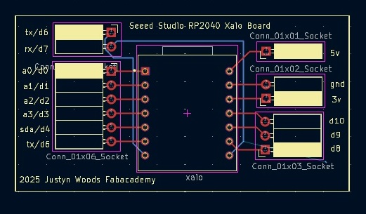
3d view of what finished board will look like

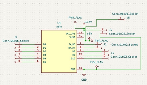
A view of the schematic layout

diagram of pcb

Close up of LED's
Here's how I did it!
Here are the items that were used
- Arduino Uno R3 Microcontroller board (with ac adapter for power)
- Breadboard
- 1 Red led
- 1 220ohm Resistor
- 1 Red wire
- 1 Black wire
First I set out my Arduino Uno R3 and left it unplugged from the wall.
I then got out my breadboard, led, resistor and wires. I inserted the negative
terminal of the LED into the breadbord, and inserted the positive (longer)
terminal 2 spaces away but remaining in the same column. In my example that column
would be the letter E-column. This is okay because the current doesn't flow along
the vertical columns, but ratheralong the horizontal rows. The same row (#10) that contains
the negative terminal is the same row that I will place one end of the black wire that
will be connected to the GND slot on the Arduino Uno R3. The black wire will be inserted
in column A, row 10.
Next I grab a red wire. I plug one end of the red wire to the 5v slot on the Arduino Uno R3
board. I now plug the other end of the red wire into column A, row 15. Also on row 15, in column
D, I plug in one terminal of the 220 ohm resistor. Now the other terminal on the resistor plugs into
column D, row 12. Row 12 is also where the positive terminal of the red led is located. This now
completes the circuit. Once power is supplied from wall or usb port via pc or battery bank, power is sent
from the power input terminal of the Arduino Uno R3 to the 5v port. The red wire carries the current to
the breadboard where the current is sent through the resistor, which limits how much current can be
passed on to any connected device or module. In this case it is a red led that will receive a reduced
flow of electricity to properly power on with being damaged from improper voltage. As stated previously,
the GND (ground) completes the circuit.
Close up of breadboard pin locations

My Hero shot of working LED on breadboard

Another angle of illumination
Led illuminated video
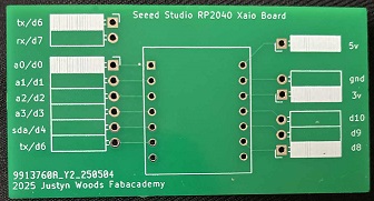
Uploaded to JLCPCB

Uploaded to JLCPCB to test if model was ready to be shipped out.
Here is the project file from Kicad
I uploaded the original file and it's now downloadable
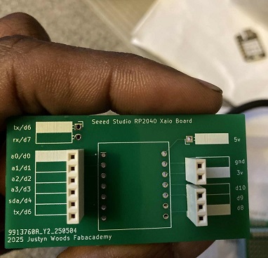
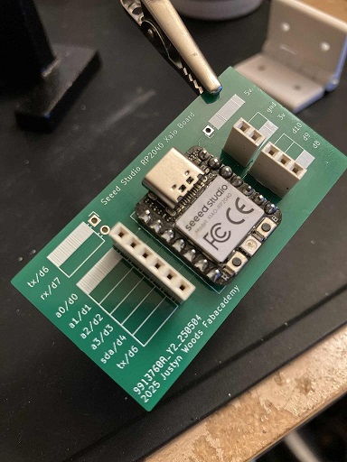
Led BoardHere is the board sent back from jlcpcb.com I have to add components
and test this board. I just need to order a connection pin for power