3. Computer controlled cutting
Week 3 Checklist
- Linkled to the group assignment page
- Explain how you created your parametric design
- Documented how you made your press construction kit
- Documented how made something with the vinyl cutter
- Include your original design files
- Included hero shots of your results
laser cutter for the parametric construction kit portion of Week 3. I do own an older laser
cutter system, but it is currently stored and not yet operational. I plan to retrieve, inspect,
and attempt to restore the machine to working condition in order to continue experimenting with
laser-based fabrication and parametric press-fit construction techniques. At this stage, my
available equipment only allowed for lightweight drag-knife cutting operations using paper-based
materials, and I was not yet able to perform laser cutting on thicker materials such as wood,
acrylic, or metal. So for this assignment all I had was a laser cutter that I bought cheap online
on fb marketplace.
Creality 5w Laser Cutter/engraver
I was able to get out my laser cutter. But was not successful at getting my design cutout
I tried cutting on a 5w creality laser machine but had no luck. The only way that I could
get any funtionality at all was saving a file in lightwave. It's software for laser machines.
I saved a file I designed in Lightwave as a gCode file on to a micro sd card. I then inserted
that same micro sd card into tf slot of the laser machine and was successful at getting the
machine to etch a surface level image on 1/8 wood sheet. I even ran a few passes and noticed
that the etching was deeper, but was still not making anything resembling a cut. Below is
an image of the test etching board I used.
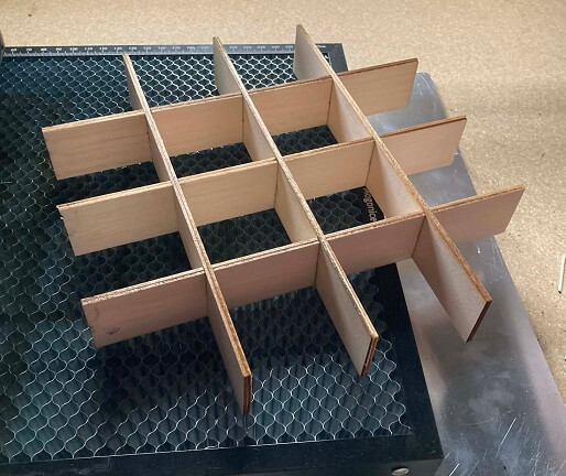
Parametric Construction Kit
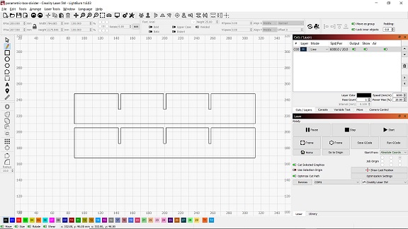
For this assignment, I designed and laser cut a Parametric 4x4 Strategy Game Board using a Creality 5W diodelaser engraver. The project was created from interlocking components that fit together using slot-based
connections and demonstrates the use of parametric design principles in a laser-cut construction kit.
Design Process
The game board consists of laser-cut pieces that slide together to create a 4x4 playing surface. The design
was developed using material thickness as a key parameter when creating the interlocking joints.
The primary design parameter was: Material Thickness = 1.5 mm By designing the slots around material thickness, the project can be adapted to different materials by
adjusting a single design parameter rather than redesigning the entire model.
Material
The project was fabricated from:
- Balsa Wood
- Dimensions: 300 mm × 100 mm × 1.5 mm
During assembly, I found that the balsa wood was very lightweight and flexible. My original design required
six interlocking pieces, but I decided to cut twelve pieces instead. By using two pieces in each location,
the assembled structure became approximately twice as thick and significantly more rigid.
No glue or adhesive was used. The additional pieces were held in place entirely by the slot-fit design and
the friction created by the press-fit joints.
Laser Settings
The parts were cut using a Creality 5W diode laser engraver with the following settings:
Setting Value
---------- -----------------
Speed = 1100 mm/min
Power = 80%
Pass Count = 2
Material = 1.5 mm Balsa Wood
These settings successfully cut through the material while maintaining acceptable edge quality and minimal burning.
Assembly
The game board was assembled using slot-fit construction techniques. The interlocking pieces slide together and
lock into position without the use of screws, nails, glue, or other fasteners.
Using twelve pieces instead of six increased the overall thickness of the assembly and improved the durability of
the finished game board while maintaining the original design concept.
Results
The completed project successfully demonstrated:
- Parametric design
- Laser cutting
- Press-fit construction
- Slot-based assembly
- Material-driven design considerations
The finished board was lightweight, reusable, and could be assembled and disassembled
without damaging the components.
What I Learned.
This assignment helped me understand how material thickness influences the design of press-fit assemblies.
I also learned how laser power, speed, and pass count affect cut quality and material penetration. Working
with thin balsa wood required design adjustments to improve strength. By increasing the number of interlocking
components from six to twelve, I was able to create a stronger and more rigid structure without changing the
overall design or using adhesives.
My parametric assembly piece
I found a shape that I liked online and brought it into the program lightburn. After opening the file
in lightburn i used the pencil tool to trace the line path of the object. Once I created the shape that
I needed, I deleted the original shape. I then cut the pieces out on my 5w laser machine and easily
inserted the pieces into the precut slots and...bingo. It was finished. No glue or adhesive to hold it.
because of it's design it holds itself together without the need of glues or fasterners of any kind.
Cutting away with the Creality
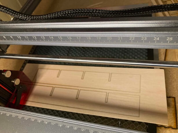
Fresh Cuts
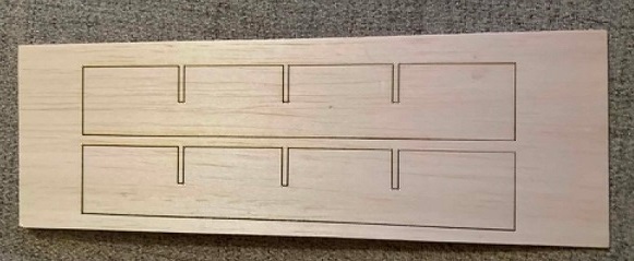
Getting them ready
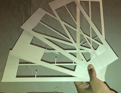
Leftovers
My Hero shot...DONE !
Videos
Here are a few video showing the machine cutting and the finished product
Video of construction kit assembled.
Cutting the walls
Here are the files used to make the kit
gCode fileDXF file
SVG file
Vinyl Cutting Workflow Documentation
For this assignment I explored computer-controlled cutting using a legacy Cricut Createvinyl cutter. Although the Cricut Create is an older generation cutting machine, it remains
capable of performing precise vector-based cuts for lightweight materials such as cardstock,
vinyl, and glossy photo paper.
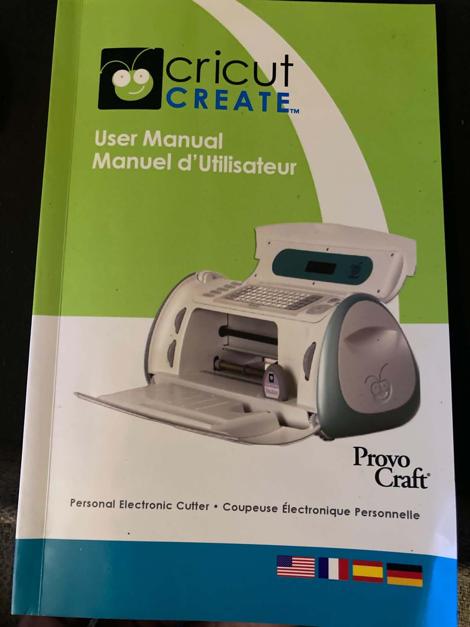
Manual for the Cricut Create
The goal of this workflow was to:- prepare digital graphics for cutting
- transfer designs into cutting software
- configure the cutter hardware
- execute test cuts
- evaluate material behavior and cutting quality
- troubleshoot hardware and software limitations
This assignment demonstrated the use of computer-controlled fabrication workflows using
legacy cutting hardware adapted to a modern Windows-based workflow.
Software and Workflow
To operate the Cricut Create on a Windows 10 computer, I used:
- Sure Cuts A Lot (SCAL 6)
- legacy Cricut communication plugins
- Adobe Photoshop for graphic preparation
SCAL (Sure Cuts A Lot) is vector cutting software capable of interfacing with older cutting
machines through third-party legacy plugins.
Because the Cricut Create is no longer officially supported by modern Cricut software platforms,
additional configuration and plugin installation steps were required in order to establish
communication between the cutter and the computer.
The setup process included:
- installing SCAL softwareThe setup process included: - installing legacy Cricut support plugins
- configuring the cutter profile inside SCAL
- verifying USB communication between the machine and the computer
Once configured, the cutter was able to receive and execute digital cutting paths from the software.
Design Preparation
To create cutting tests, I designed several simple graphics and shapes including:
a recycle logo
circular geometry
a raindrop shape
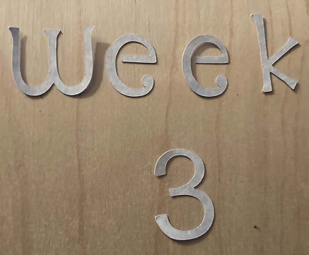
text-based phrase cutting
Within Photoshop, I used the Custom Shape Tool to generate vector-style graphics and symbols.
The completed designs were exported as PNG image files and imported into SCAL 6 for cutting preparation.
After importing the graphics into SCAL, the software generated cut paths around the imported images.
This workflow demonstrated the conversion of digitally created graphics into machine-readable fabrication paths.
First cuts
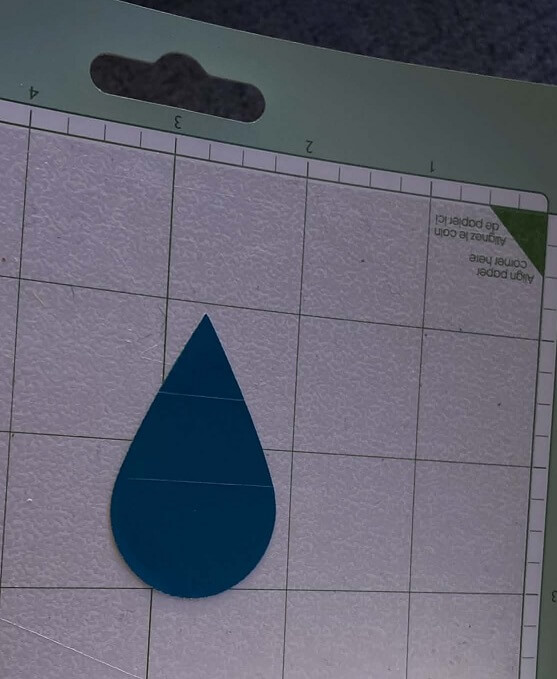
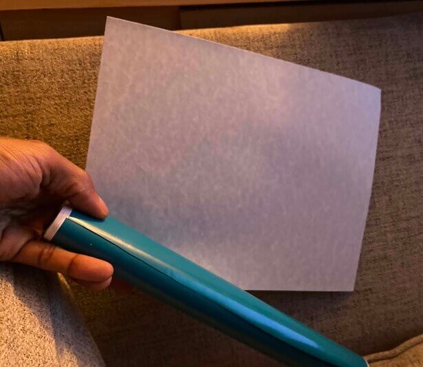
Raindrop cutout on vinyl
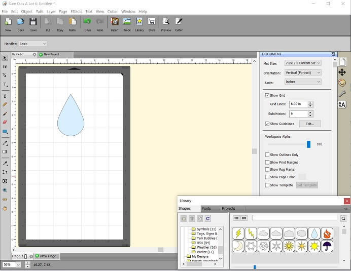
Raindrop in SCAL
Material Testing
For cutting experiments, I tested multiple lightweight materials including:
thick cardstock
glossy photo paper
Materials
Both materials were mounted to the adhesive cutting mat before loading into the cutter.
The glossy photo paper produced smoother visual surfaces and cleaner edge appearance,
while the cardstock provided greater rigidity and durability after cutting.
Testing multiple materials allowed comparison of:
- edge quality
- cutting consistency
- material stability
- surface finish
- adhesion performance during cutting
The cutting mat adhesive strength was important for preventing material movement during machine operation.
Machine Setup and Operation
The material was aligned to the machine registration corner and pressed firmly onto
the adhesive cutting mat. The cutting mat was then inserted underneath the cutter rollers
and loaded into the machine using the onboard load controls.
Once the machine entered ready position, the cutter settings were accessed within SCAL 6 and
the cutting job was initiated directly from the software interface. The Cricut Create then
executed the programmed cutting paths automatically.
Machine Behavior and Troubleshooting
The Cricut Create used during this assignment was purchased secondhand locally and exhibited
inconsistent operational behavior during some cutting jobs. While several cuts completed
successfully, some cutting operations unexpectedly stopped before completion even though
the software interface remained active.
This required:
- restarting cutting operations
- simplifying design geometry
- reducing graphic complexity
- repeating material alignment
- verifying software communication stability
- checking cutting mat adhesion
Because the Cricut Create is legacy hardware operating through unofficial third-party software
support, intermittent communication instability may have contributed to incomplete cutting operations.
Additionally, the SCAL trial software occasionally generated unintended internal cut lines within
imported graphics, requiring additional inspection of the generated toolpaths before fabrication.
Despite these limitations, the cutter successfully produced:
- text cuts
- geometric shapes
- symbolic graphics
- repeated material tests
Iterative Testing and Observations
During testing I observed several important fabrication considerations:
- simpler vector graphics produced more reliable cuts
- proper material adhesion reduced shifting during cutting
- clean graphic preparation improved cut accuracy
- legacy hardware required repeated troubleshooting and testing
- software-generated toolpaths required inspection before cutting
- different materials responded differently to blade cutting behavior
These iterative tests improved understanding of:
- computer-controlled fabrication workflows
- drag-knife cutting behavior
- software-to-machine communication
- material handling during cutting operations
- troubleshooting legacy fabrication hardware
Results
The Cricut Create successfully converted multiple digital graphics into physical cut
outputs using computer-controlled cutting methods.
Successful outputs included:
- phrase cutting
- geometric forms
- symbolic graphics
- material comparison tests
This workflow demonstrated:
- digital-to-physical fabrication
- vector-based cutting operations
- machine setup and configuration
- material experimentation
- iterative troubleshooting
- fabrication workflow adaptation using legacy hardware
Reflection
This assignment demonstrated that older computer-controlled cutting systems can still participate
in modern digital fabrication workflows when combined with alternative software tools and iterative
troubleshooting methods. Although the Cricut Create lacks many features found in newer fabrication
systems, it remained capable of producing accurate physical outputs from digitally prepared designs.
The process emphasized the importance of:
- workflow adaptability
- material experimentation
- software compatibility
- troubleshooting techniques
- iterative fabrication testing
- machine setup and calibration
Working with legacy hardware also highlighted how fabrication workflows often require problem
solving, repeated testing, and adjustment in order to achieve successful physical results.
Project file & How to guide
Included below are a guide on how to use legacy software and a legacy cutter
to design and cut out objects on thin material on current pc hardware. also
I have th raindrop file that I cut out.
How to guide
Raindrop SCAL project file