WEEK 9: Input Devices
Assignment - Measure something: add a sensor to a microcontroller board that you have designed and read it
1. PCB Board - ESP32 MPC
2. Sensors - DHT11 and PIR Sensor
Sensors
Sensors play a crucial role in various applications by detecting physical, chemical, or biological properties and converting them into electrical signals.
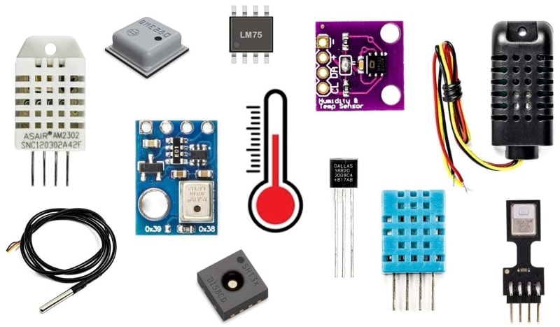
Temperature Sensors
Temperature sensor is a device, used to measure the temperature using an electrical signal. It requires a thermocouple or RTD(Resistance temperature Detector). It is the most common and most popular sensor. Temperature sensor, the change in the temperature correspond to change in its physical property like resistance or voltage.
Examples
-> Thermocouples
-> Resistance Temperature Detectors (RTD)
-> Thermistors
-> Infrared Temperature Sensors
Working
The working of the sensor is the voltage that read across to the diode. If increment in voltage, then the temperature increases and there is a voltage decrement between the transistors terminals of emitter & base. That data saved by the sensor. If the difference in voltage is amplified, then analog signal is generated by the device, and it is directly proportional to the temperature.
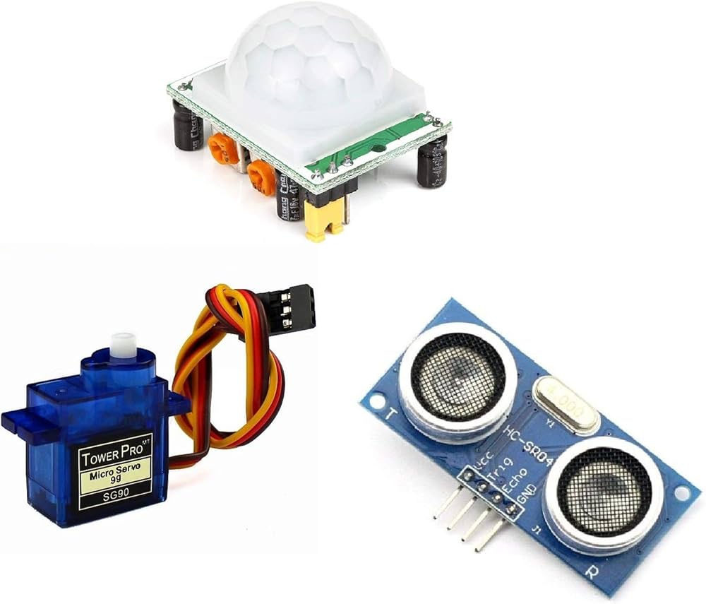
Motion Sensors
A motion sensor is an electronic device designed to detect movement and changes in the surrounding environment. It is commonly used in security systems, lighting control, and home automation. With various technologies available, including infrared, ultrasonic, and microwave detection, the motion sensor can accurately sense motion and trigger customized responses. From activating alarms to turning on lights, motion sensors provide seamless automation and energy efficiency.
Examples
-> Passive Infrared (PIR) Sensors
-> Ultrasonic Sensors
-> Microwave Sensors
Working
The motion sensor work by detecting changes in infrared radiation or the presence of heat and movement within their coverage area. The most common type of motion sensor is a passive infrared (PIR) sensor, which detects changes in the infrared radiation emitted by objects in its field of view. When an object moves within the sensor's field of view and emits heat, the sensor registers the change and generates an electrical signal. This signal can then be used to trigger an alarm or activate other devices.
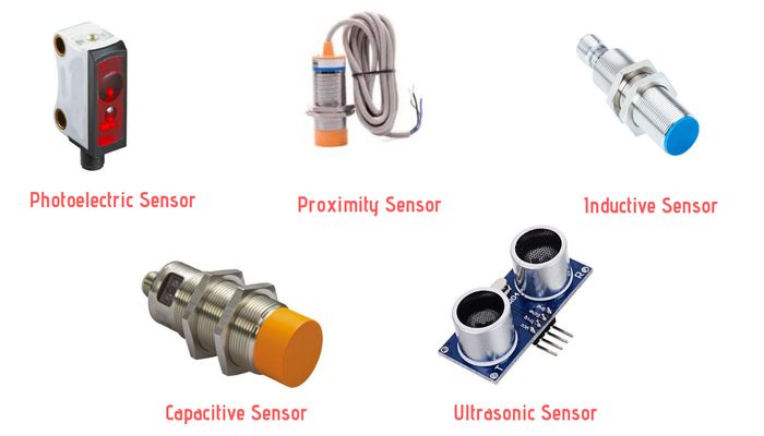
Proximity Sensors
A proximity sensor often emits an electromagnetic field or a beam of electromagnetic radiation (infrared, for instance), and looks for changes in the field or return signal. The object being sensed is often referred to as the proximity sensor's target. Different proximity sensor targets demand different sensors. For example, a capacitive proximity sensor or photoelectric sensor might be suitable for a plastic target; an inductive proximity sensor always requires a metal target.
Examples
-> Capacitive Proximity Sensors
-> Inductive Proximity Sensors
-> IR Proximity sensors
-> Ultrasonic Proximity Sensors
Working
The working principle of proximitors is as follows: As the shaft moves across the surface of the probe, the magnetic field is absorbed by the surface of the material. Eddy currents are formed in the shaft material, attenuating the probe coil field.
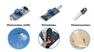
Light Sensors
Light sensors are a type of photodetector (also called photosensors) that detect light. Different types of light sensors can be used to measure illuminance, respond to changes in the amount of light received, or convert light to electricity.
Examples
-> Photodiodes
-> Light Dependent Resistors
-> Infrared Sensors
Working
The light sensor working principle is based on the photoelectric effect. The sensor uses photosensitive materials that can respond to the presence of light. These materials can be semiconductors, photoconductive materials, or photovoltaic materials. When light hits the photosensitive material, its electrical properties change. This change can manifest as a variation in resistance, the generation of current, or a change in voltage. The sensor then converts this change into an electrical signal.
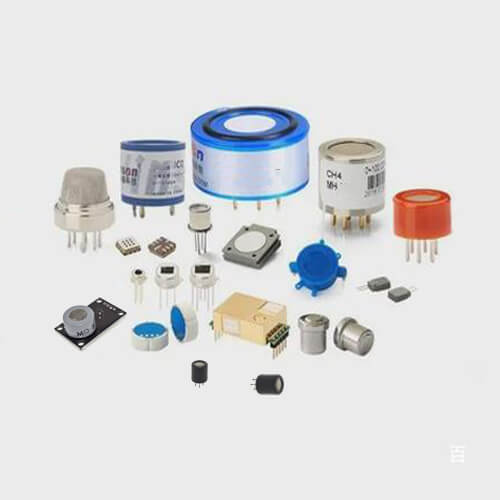
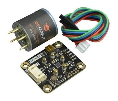
Gas Sensors
The gas sensor is a device used to monitor the presence or level of gas in a stationary environment. Commonly used in coal mines, petroleum, chemical, municipal, medical, transportation, family, and so on. Gas sensors can measure the presence and concentration of combustible, flammable, toxic gases, or oxygen consumption.
Examples
-> Carbon Monoxide (CO) Sensors
-> Methane (CH4) Sensors
-> Oxygen (O2) Sensors
Working
Gas sensors detect the presence or concentration of gases by utilizing various physical or chemical reactions that change a property of the sensor's material or circuitry, resulting in a measurable signal, often electrical.
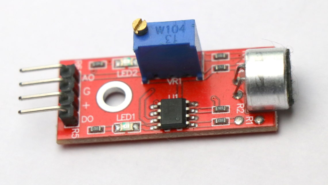
Sound Sensors
A sound sensor is a device that converts sound waves into an electrical signal that can be processed by an electrical circuit. They can be used to detect and measaure the amplitude, frequency and duration of sound waves.
Examples
-> Microphones
-> Piezoelectric Sensors
-> OMEMS Acoustic Sensors
Working
It works similar to our ears. Our Ears have a diaphragm which converts the detected the vibration and converts it in the signal. Similarly, the sound sensors convert the vibration into audio signal (voltage and current proportional) with the help of a microphone.
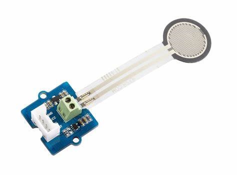
Force and Weight Sensors
A force sensor, which is also known as a load cell or force transducer, is a sensor that measures force by converting the input of mechanical force into the output of an electrical signal. As the force is applied to the sensor, its electrical output signal can be measured, converted, and standardized.
Examples
-> Load cells
-> PStrain Gauges
Working
A force sensor measures mechanical forces, like a secret handshake between machines and the real world. These ingenious devices convert mechanical force into electrical signals, enabling us to measure, analyze, and interact with the physical world around us.
Bio Sensors
A biosensor is a device that can report the presence or activity of analytes using a biomolecular component providing specificity to the sensor by binding or interacting with the analyte and is able to cause a detectable change in mass, fluorescence, electric charge, or refractive index, and a transducer element, able to transform this interaction into a suitable electronic signal.
Examples
-> Glucose Sensors
-> Electrochemical Biosensors
Working
The term “biosensor” is short for “biological sensor.” The device is made up of a transducer and a biological element that may be an enzyme, an antibody or a nucleic acid. The bioelement interacts with the analyte being tested and the biological response is converted into an electrical signal by the transducer.
Assignemnt
Objective
The objective of this assignment is to integrate a sensor with a custom-designed microcontroller board, acquire real-time data, and analyze the measurements. This exercise will enhance the understanding of sensor interfacing, data acquisition, and real-world signal processing using an embedded system.
Software Used
I have designed the microcontroller board using KiCad and EasyEDA. The board features an ESP32 and includes external pins for power supply, a serial port for flashing code, and read/write operations.
Part 1: PCB Design
Creating Schematic Diagram
Component Selection
1. Microcontroller: ESP32
2. Passive Components: Resistors, Capacitors
3. Protection Components: Diodes
4. Indicators: LED
5. Connectors:
6. Sensors: Temperature Sensor, PIR sensor
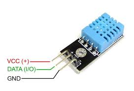
Temperature sensor
DHT11 Temperature & Humidity Sensor features a temperature & humidity sensor complex with a calibrated digital signal output. By using the exclusive digital-signal-acquisition technique and temperature & humidity sensing technology, it ensures high reliability and excellent long-term stability. This sensor includes a resistive-type humidity measurement component and an NTC temperature measurement component, and connects to a highperformance 8-bit microcontroller, offering excellent quality, fast response, anti-interference ability and cost-effectiveness.
General Specifications
| Parameter | Specification |
|---|---|
| Sensor Type | Digital Temperature and Humidity Sensor |
| Operating Voltage | 3.3V - 5V DC |
| Temperature Range | 0°C to 50°C |
| Temperature Accuracy | ±2°C |
| Humidity Range | 20% to 90% RH |
| Humidity Accuracy | ±5% RH |
| Resolution | Temperature: 1°C, Humidity: 1% |
| Sampling Rate | 1 Hz (1 reading per second) |
| Operating Current | 0.5 mA (average) |
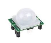
PIR sensor
PIRs are basically made of a pyroelectric sensor (https://adafru.it/aKh) (which you can see below as the round metal can with a rectangular crystal in the center), which can detect levels of infrared radiation. Everything emits some low level radiation, and the hotter something is, the more radiation is emitted. The sensor in a motion detector is actually split in two halves. The reason for that is that we are looking to detect motion (change) not average IR levels. The two halves are wired up so that they cancel each other out. If one half sees more or less IR radiation than the other, the output will swing high or low.
General Specifications
| Parameter | Specification |
|---|---|
| Sensor Type | Passive Infrared (PIR) Motion Sensor |
| Operating Voltage | 3V - 5V DC |
| Detection Range | Up to 7 meters |
| Detection Angle | 110° |
| Output Type | Digital (High when motion detected) |
| Delay Time | Adjustable (0.3s to 5 minutes) |
| Operating Temperature | -20°C to 50°C |
| Power Consumption | Low (Standby: < 50µA) |
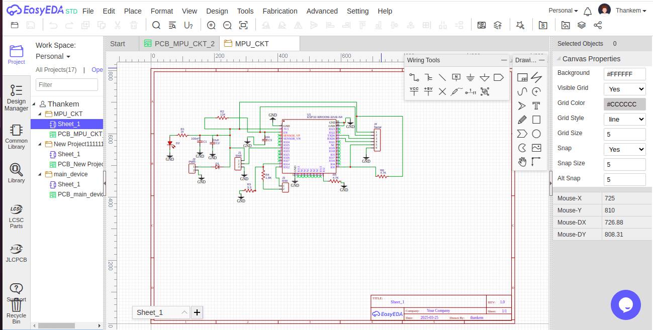
Schematic Diagram
2. Add components using the "Place component" tool.
3. Assign values and labels to components.
4. Connect components using wires.
5. Use labels for organized wiring.
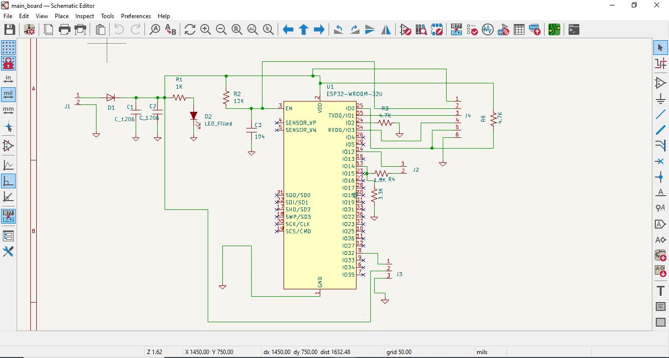
Schematic Design & ERC Verification
-> Created a complete USB circuit schematic ensuring correct connections.
-> Used Electrical Rule Checker (ERC) to validate the schematic.
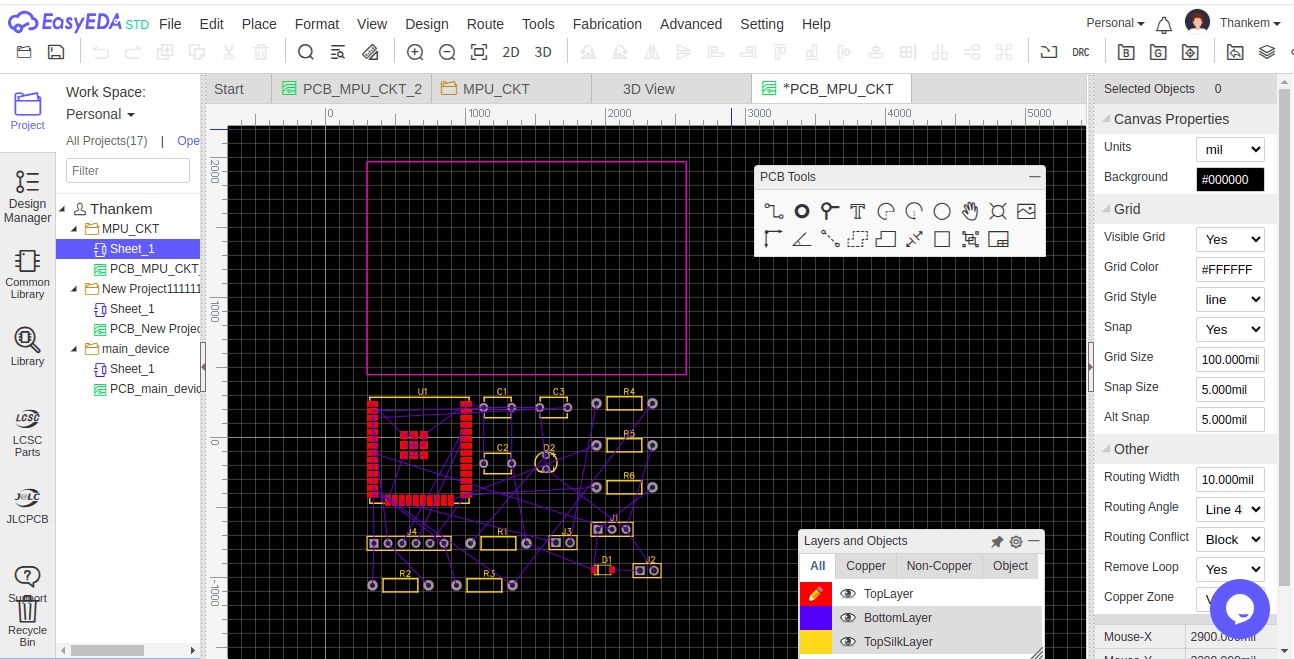
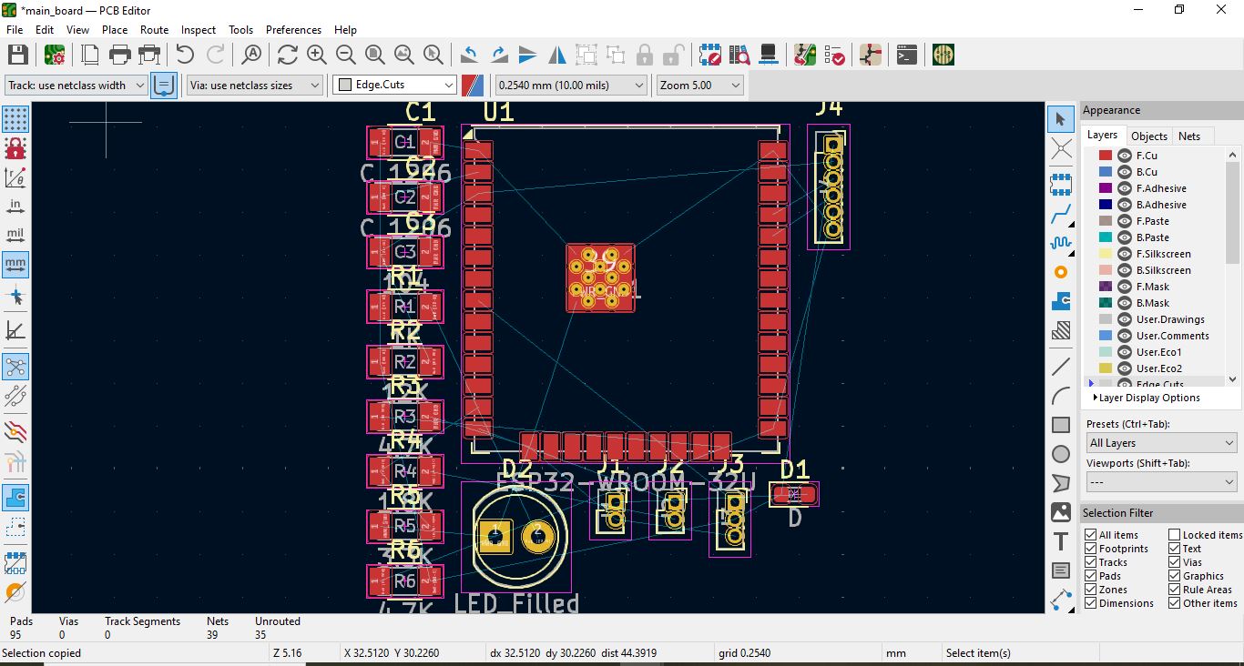
PCB Layout & Routing
The PCB layout design is performed by transferring the schematic components onto the PCB Editor. Proper placement of components is crucial for optimizing routing and signal integrity. After arranging components, the routing process begins, where electrical connections are made using copper traces. KiCad’s Design Rules Check (DRC) helps in verifying correct routing and ensuring compliance with spacing and manufacturing constraints. For multi-layer boards, via placement is essential to maintain signal flow between layers. After routing is completed, the design is visually inspected for errors.
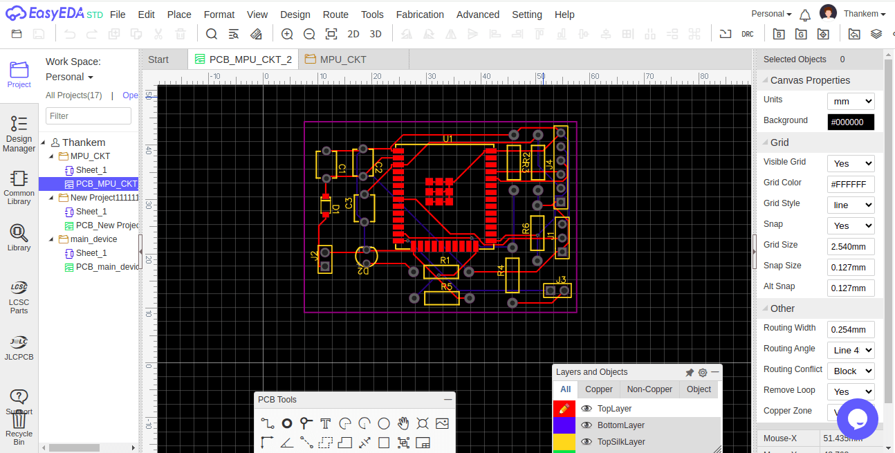
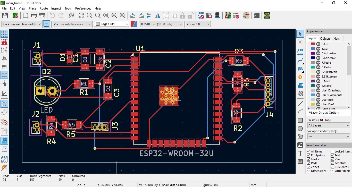
Routing the PCB
2. Route traces manually or use the auto-router.
3. Ensure power and ground planes are properly connected.
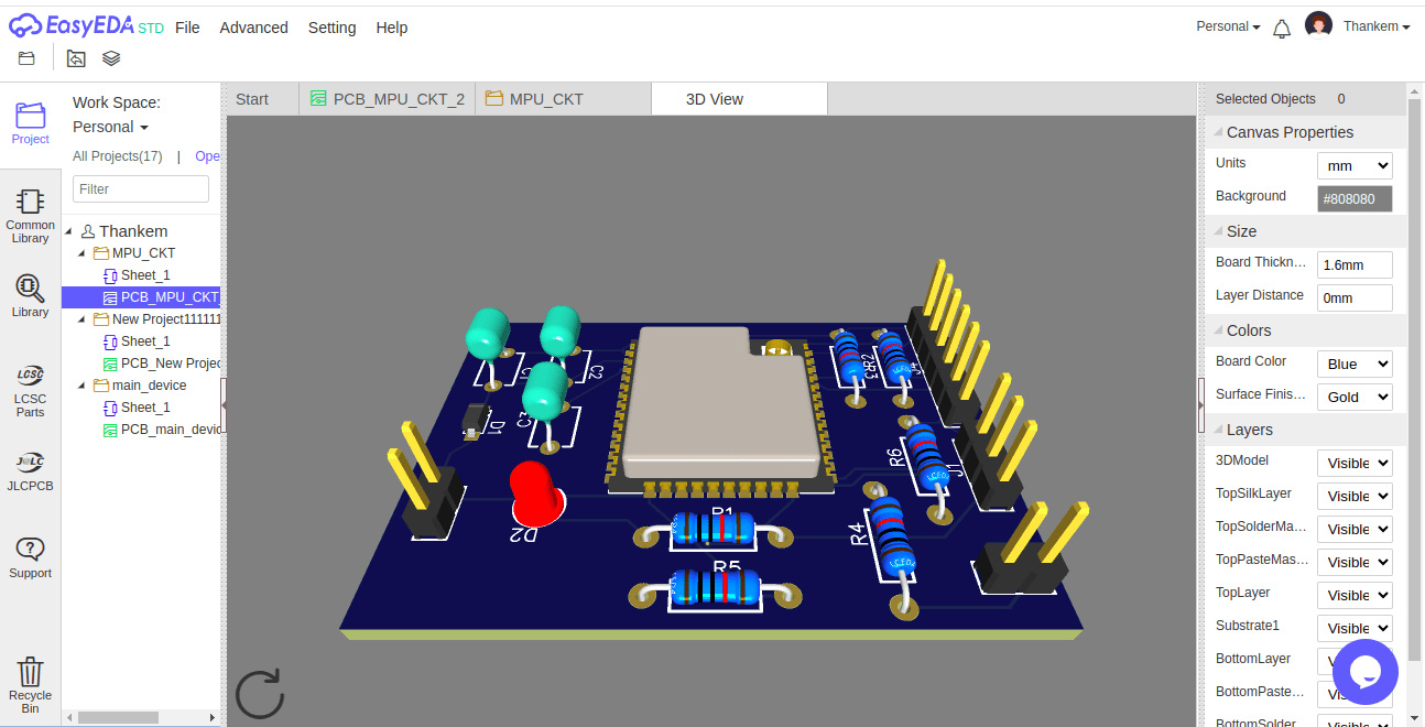
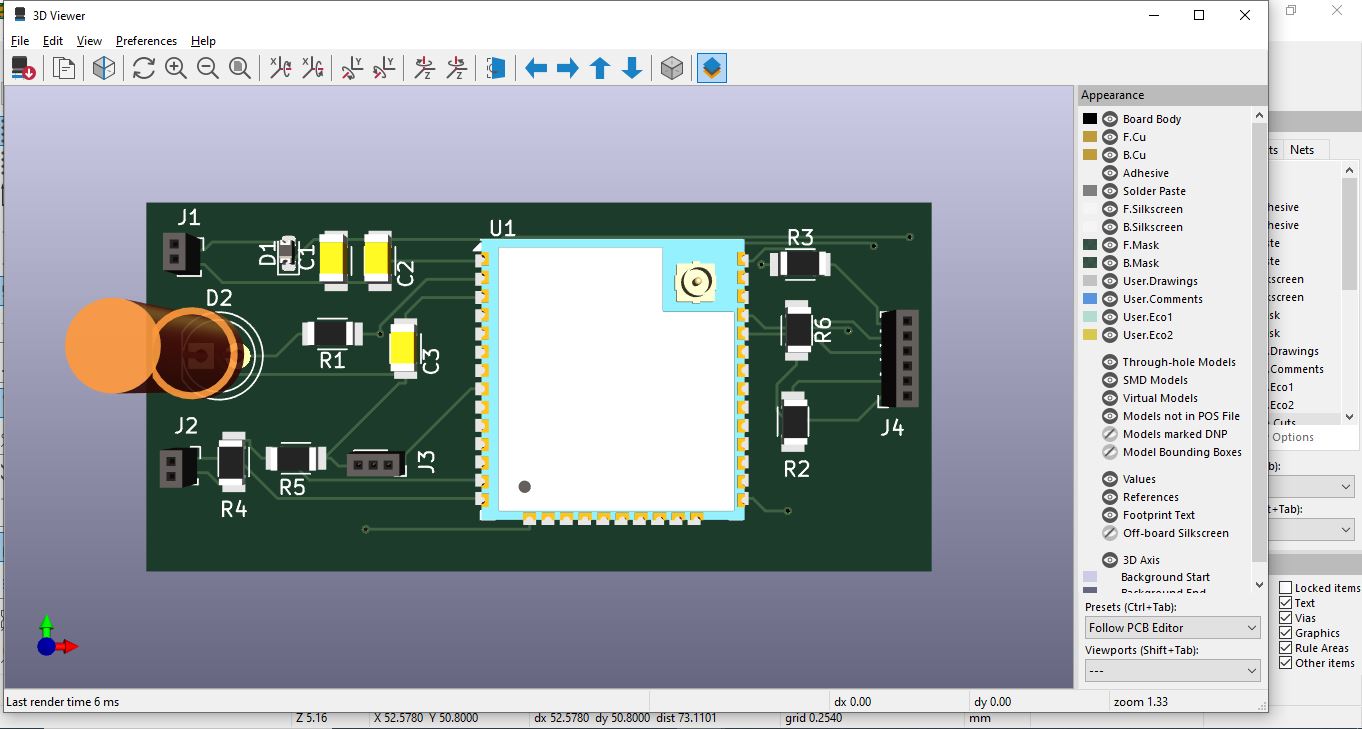
3D Viewer of PCB Board
2. Inspect the PCB in 3D to ensure proper placement and alignment.
3. Rotate and zoom to check for clearance and silkscreen positioning.
Generating Gerber Files for Manufacturing
To manufacture the PCB, Gerber files are generated, which include copper layers, solder mask, and silkscreen details. Additionally, a drill file is produced for hole placement. Before sending the design for fabrication, a 3D view is examined to verify component alignment and board structure. Once the design is finalized, the files are sent to a PCB manufacturer for production.
Generate Gerber Files
2. Select the required layers (Top, Bottom, Silkscreen, Mask, Edge.Cuts).
3. Click "Plot" to generate Gerber files.
4. Open "Generate Drill Files."
5. Set correct settings and export drill file.
6. Use Gerber Viewer to check file correctness.
Arduino IDE Code
This code is designed to read temperature data from a DHT11 sensor and detect motion using a PIR (Passive Infrared) sensor with an ESP32 microcontroller. The temperature is printed to the serial monitor, and motion detection is indicated with a message whenever motion is detected. The system takes readings every 60 seconds. This setup is useful for applications such as home automation, security systems, and environmental monitoring.
Video
Download Design Files
Click on the links below to download the Output files:
Pick and Place File
.SVG file
GerberFILE
BOM
Arduino IDE Program