Week 11 : Embedded Networking and Communications


 Objective of this Week

  • To establish communication between two projects and exchange data messages.


Adafruit

  • Adafruit Industries is a U.S.-based open-source hardware company founded by Limor “Ladyada” Fried in 2005.
  • It designs, manufactures, and sells electronics components, tools, and kits for makers, students, and engineers.
  • Adafruit is known for its beginner-friendly products and detailed online tutorials.
  • It offers a wide range of development boards like Feather, Trinket, and Metro (Arduino-compatible).
  • The company also supports IoT projects through Adafruit IO, a cloud platform for data logging and device control.
  • Its product catalog includes sensors, LEDs, displays, motor drivers, and microcontrollers.
  • Adafruit encourages open-source learning by providing free code libraries and schematics.
  • It has a strong online community and learning portal called the Adafruit Learning System.
  • The company promotes STEM education through hands-on electronics projects.
  • Overall, Adafruit empowers innovators to prototype, learn, and build creative electronic systems easily.


Overview

For this task, we developed an Adafruit IO-based servo control system, where one device (sender) transmits data to the cloud, and another (receiver) reads that data to perform an action. This fulfilled the goal of sending a message between two networked projects.


Project Description

  • The experiment demonstrates real-time cloud-to-device communication using XIAO ESP32-C3 and Adafruit IO.
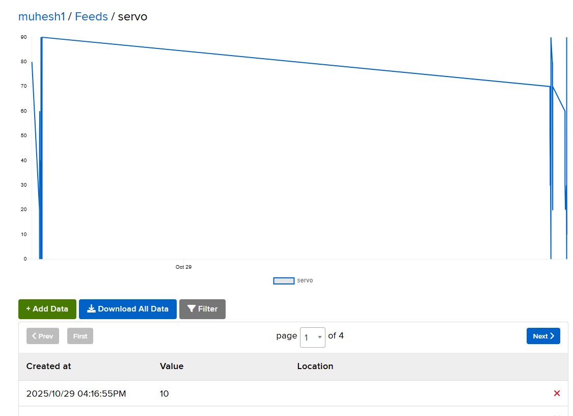
  • A slider widget on the Adafruit IO dashboard acts as the sender, transmitting angle values through a cloud feed named “servo”.
  • The ESP32-C3 microcontroller, as the receiver, subscribes to this feed and moves a servo motor to the specified position.

Thus, the message sent between the two projects is the servo angle value , transmitted via the internet using MQTT protocol.
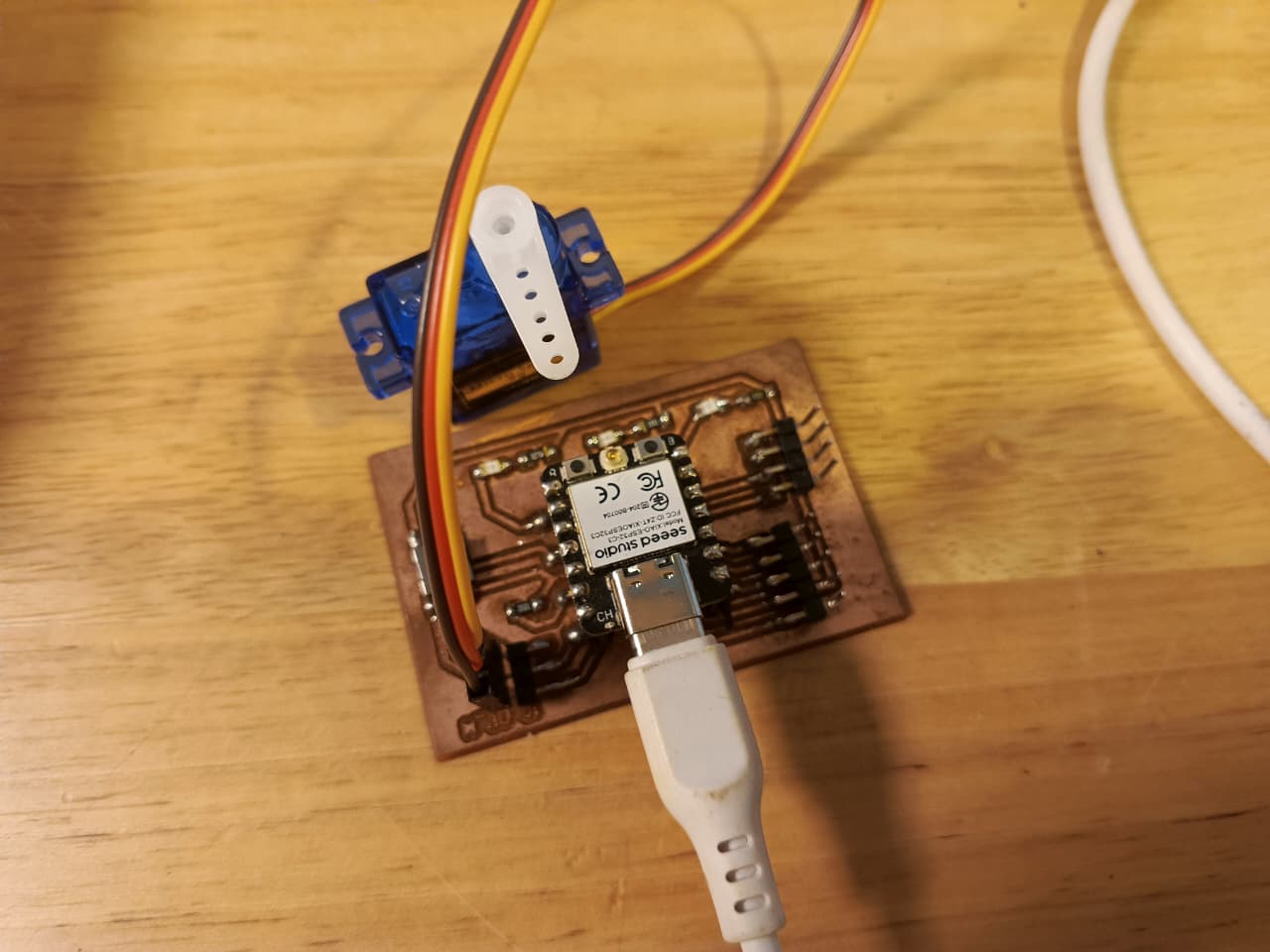

Components Used

  • XIAO ESP32-C3
  • Servo Motor (SG90)
  • USB Type-C Cable
  • Adafruit IO Account
  • PCB fabricated board


Dashboard Setup on Adafruit IO

  • Log in to https://io.adafruit.com

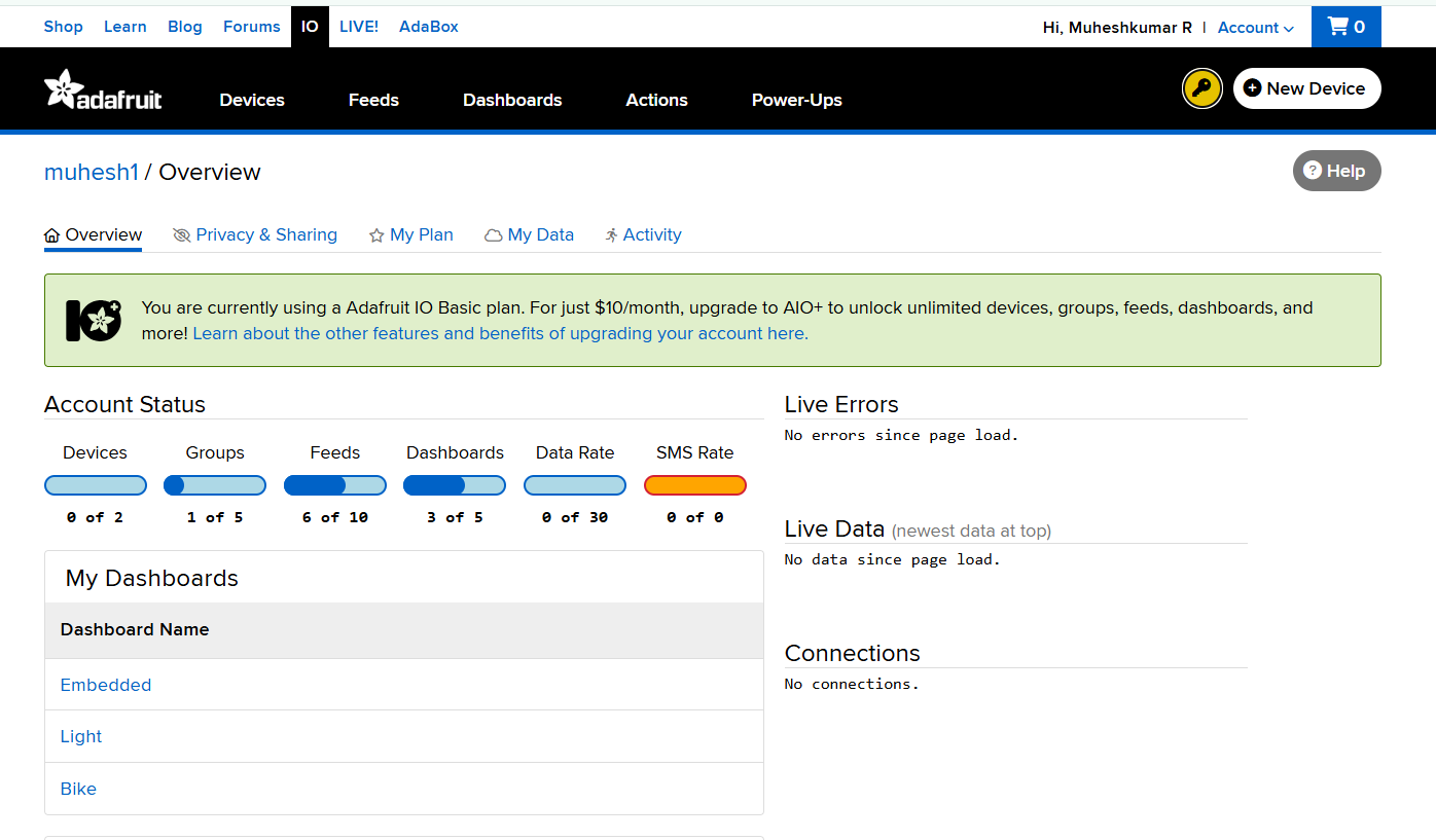
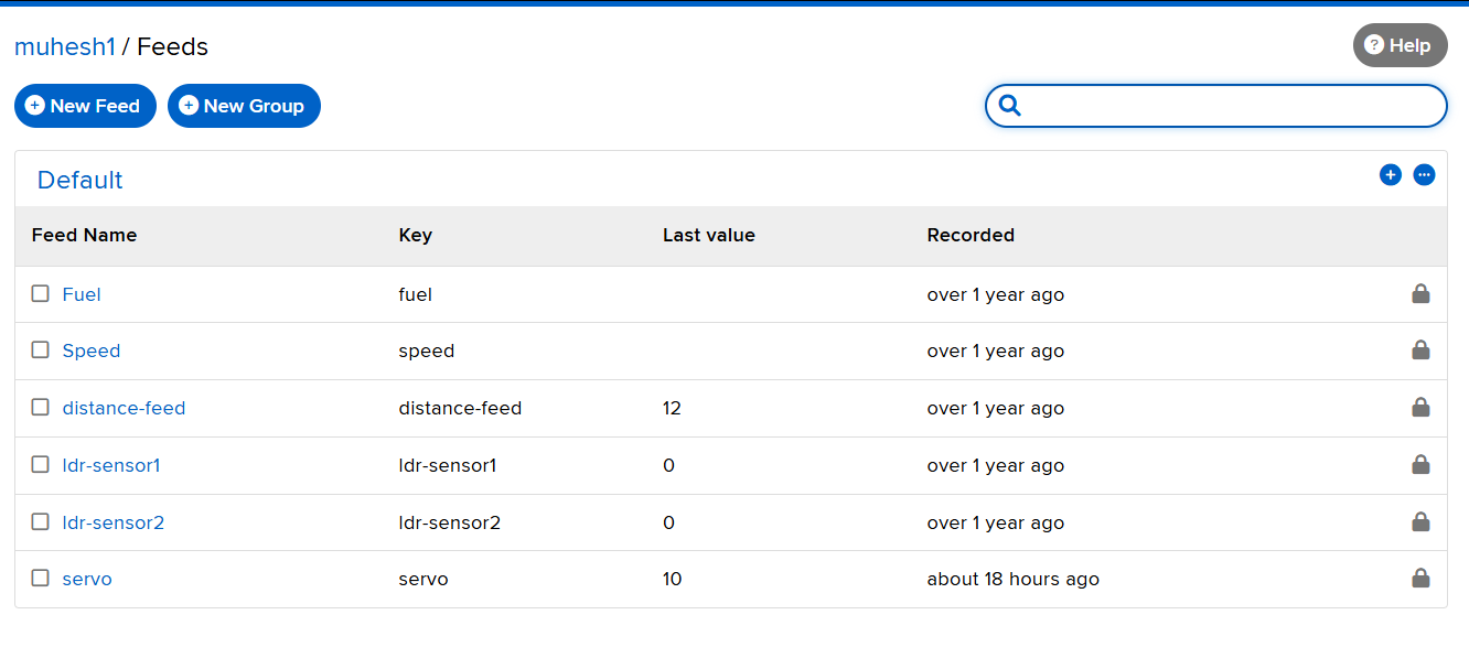
  • Navigate to Feeds → New Feed → Name it “servo”
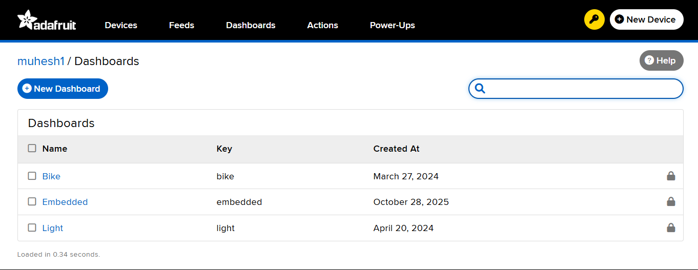
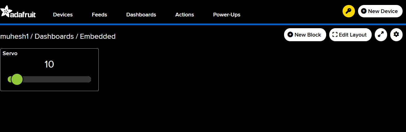
  • Go to Dashboards → Create New Dashboard named “Embedded” → Add a Slider Block
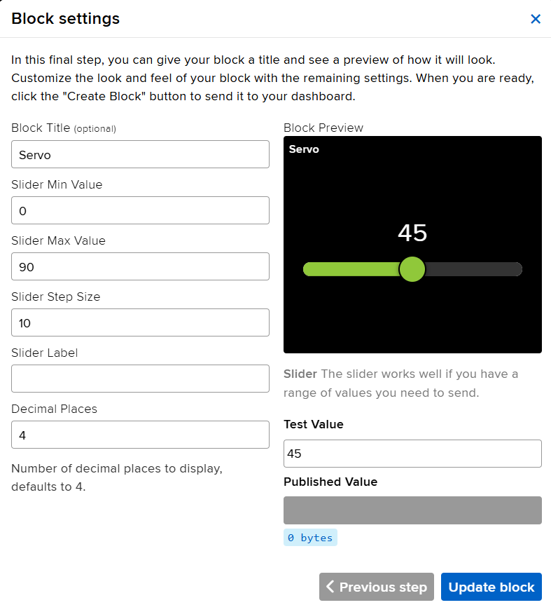
  • Configure the slider:
    • Feed: servo
    • Range: 0 to 180
    • Send Value on Change: Enabled

This dashboard now acts as a virtual transmitter, sending data values to the subscribed xiao seed studio ESP32-C3 board.


Arduino Code

#include <WiFi.h>
#include "AdafruitIO_WiFi.h"
#include <ESP32Servo.h>

// Adafruit IO Credentials
#define IO_USERNAME  "muhesh1"
#define IO_KEY       "aio_FxIC98S56I4KYL6JE7wJM38j0rXV"

// Wi-Fi Credentials
#define WIFI_SSID "Forge_office"
#define WIFI_PASS "Forged@Forge"

// Create Adafruit IO instance
AdafruitIO_WiFi io(IO_USERNAME, IO_KEY, WIFI_SSID, WIFI_PASS);

// Define servo feed
AdafruitIO_Feed *servoFeed = io.feed("servo");

// Servo configuration
Servo myServo;
int servoPin = 6;  // GPIO6 on XIAO ESP32-C3

void setup() {
  Serial.begin(115200);
  myServo.attach(servoPin);

  Serial.print("Connecting to Adafruit IO");
  io.connect();
  servoFeed->onMessage(handleServo);

  while (io.status() < AIO_CONNECTED) {
    Serial.print(".");
    delay(500);
  }
  Serial.println("\nConnected to Adafruit IO!");
}
void loop() {
  io.run();  // Keep the connection alive
}
void handleServo(AdafruitIO_Data *data) {
  int angle = data->toInt();
  Serial.print("Received Servo Angle: ");
  Serial.println(angle);
  angle = constrain(angle, 0, 180);
  myServo.write(angle);
}


System Operation

  1. The ESP32-C3 connects to Wi-Fi and authenticates with Adafruit IO.
  1. The Adafruit IO slider publishes a new value to the “servo” feed.
  1. The subscribed ESP32-C3 receives this message instantly.
  1. The servo motor rotates to match the received angle.
  1. The serial monitor logs the received messages, confirming successful communication.


Working video


Conclusion

Through this task, I achieved real-time servo control using an Adafruit IO cloud feed, fulfilling the requirement of sending a message between two projects. This experiment illustrates how embedded networking enables remote device control, data sharing, and system integration across cloud-based platforms — an essential component of modern IoT engineering.

Board-to-Board Communication Demonstration

As part of the networking and communications assignment, wireless communication was established between two independent embedded systems using a Seeed Studio XIAO ESP32-C3 and a Seeed Studio XIAO ESP32-S3. The objective was to demonstrate direct board-to-board message exchange without requiring a Wi-Fi router or external network infrastructure.

To achieve this, the ESP-NOW protocol developed by Espressif was used. ESP-NOW enables peer-to-peer communication between ESP32 devices and allows messages to be transmitted directly over the 2.4 GHz wireless channel. This approach provides low latency communication and is particularly useful for embedded systems that need to exchange data efficiently.

Hardware Used

  • Seeed Studio XIAO ESP32-C3
  • Seeed Studio XIAO ESP32-S3
  • USB Type-C Cables
  • Arduino IDE
ESP32-C3 and ESP32-S3 Communication Setup

Figure: Experimental setup showing the XIAO ESP32-C3 and XIAO ESP32-S3 development boards used for wireless communication testing.

Communication Architecture

Both development boards were configured as ESP-NOW peers. Each board stored the MAC address of its communication partner and registered transmission and reception callback functions. This configuration enabled bidirectional communication, allowing both boards to send and receive messages.

The XIAO ESP32-C3 was configured to communicate with the XIAO ESP32-S3 using its MAC address. Similarly, the XIAO ESP32-S3 was configured to communicate with the XIAO ESP32-C3. Messages entered through the Serial Monitor were transmitted wirelessly and displayed on the receiving board.

Obtaining the MAC Address of the ESP32 Boards

Before configuring ESP-NOW communication, the MAC address of each development board must be identified. ESP-NOW uses the MAC address of the target device to establish direct peer-to-peer communication. Therefore, obtaining the correct MAC address is an important step before programming the communication protocol.

A simple Wi-Fi utility program was uploaded to both the XIAO ESP32-C3 and XIAO ESP32-S3 boards. The program initializes the Wi-Fi module in Station (STA) mode and prints the unique MAC address of the board to the Serial Monitor.


#include <WiFi.h>

void setup()
{
    Serial.begin(115200);

    delay(2000);

    WiFi.mode(WIFI_STA);

    Serial.print("MAC Address: ");
    Serial.println(WiFi.macAddress());
}

void loop()
{
}

After uploading the program, the Serial Monitor was opened at 115200 baud. The MAC address of each board was displayed and recorded for use in the ESP-NOW peer configuration.

ESP32 MAC Address Output

Figure: Serial Monitor displaying the MAC address of the development board.

The following MAC addresses were obtained during testing:

  • XIAO ESP32-C3: E4:B3:23:C4:5F:E0
  • XIAO ESP32-S3: 3C:0F:02:DD:62:94

These MAC addresses were then added to the ESP-NOW communication programs so that each board could identify and communicate with its corresponding peer device.

XIAO ESP32-C3 Program

The XIAO ESP32-C3 was programmed to function as both a transmitter and receiver. Any text entered into the Serial Monitor was transmitted wirelessly to the XIAO ESP32-S3 using ESP-NOW.


#include 
#include 

typedef struct
{
  char text[100];
} MessageData;

MessageData msg;

uint8_t peerAddress[] =
{
  0x3C, 0x0F, 0x02,
  0xDD, 0x62, 0x94
};

void OnDataSent(
  const wifi_tx_info_t *tx_info,
  esp_now_send_status_t status)
{
  Serial.print("Send Status: ");

  if(status == ESP_NOW_SEND_SUCCESS)
    Serial.println("SUCCESS");
  else
    Serial.println("FAILED");
}

void OnDataRecv(
  const esp_now_recv_info_t *recv_info,
  const uint8_t *incomingData,
  int len)
{
  MessageData incomingMsg;

  memcpy(
    &incomingMsg,
    incomingData,
    sizeof(incomingMsg));

  Serial.print("Received: ");
  Serial.println(incomingMsg.text);
}

void setup()
{
  Serial.begin(115200);

  WiFi.mode(WIFI_STA);
  WiFi.disconnect();

  Serial.println("ESP32-C3 Ready");

  if(esp_now_init() != ESP_OK)
  {
    Serial.println("ESP-NOW Init Failed");
    return;
  }

  esp_now_register_send_cb(OnDataSent);
  esp_now_register_recv_cb(OnDataRecv);

  esp_now_peer_info_t peerInfo = {};

  memcpy(
    peerInfo.peer_addr,
    peerAddress,
    6);

  peerInfo.channel = 0;
  peerInfo.encrypt = false;

  esp_now_add_peer(&peerInfo);
}

void loop()
{
  if(Serial.available())
  {
    String text =
      Serial.readStringUntil('\n');

    text.trim();

    if(text.length())
    {
      memset(
        msg.text,
        0,
        sizeof(msg.text));

      text.toCharArray(
        msg.text,
        sizeof(msg.text));

      esp_now_send(
        peerAddress,
        (uint8_t *)&msg,
        sizeof(msg));

      Serial.print("Sent: ");
      Serial.println(text);
    }
  }
}

XIAO ESP32-S3 Program

The XIAO ESP32-S3 was similarly configured as both a transmitter and receiver. Incoming messages were displayed in the Serial Monitor, enabling two-way communication between the boards.


#include 
#include 

typedef struct
{
  char text[100];
} MessageData;

MessageData msg;

uint8_t peerAddress[] =
{
  0xE4, 0xB3, 0x23,
  0xC4, 0x5F, 0xE0
};

void OnDataSent(
  const wifi_tx_info_t *tx_info,
  esp_now_send_status_t status)
{
  Serial.print("Send Status: ");

  if(status == ESP_NOW_SEND_SUCCESS)
    Serial.println("SUCCESS");
  else
    Serial.println("FAILED");
}

void OnDataRecv(
  const esp_now_recv_info_t *recv_info,
  const uint8_t *incomingData,
  int len)
{
  MessageData incomingMsg;

  memcpy(
    &incomingMsg,
    incomingData,
    sizeof(incomingMsg));

  Serial.print("Received: ");
  Serial.println(incomingMsg.text);
}

void setup()
{
  Serial.begin(115200);

  WiFi.mode(WIFI_STA);
  WiFi.disconnect();

  Serial.println("ESP32-S3 Ready");

  if(esp_now_init() != ESP_OK)
  {
    Serial.println("ESP-NOW Init Failed");
    return;
  }

  esp_now_register_send_cb(OnDataSent);
  esp_now_register_recv_cb(OnDataRecv);

  esp_now_peer_info_t peerInfo = {};

  memcpy(
    peerInfo.peer_addr,
    peerAddress,
    6);

  peerInfo.channel = 0;
  peerInfo.encrypt = false;

  esp_now_add_peer(&peerInfo);
}

void loop()
{
  if(Serial.available())
  {
    String text =
      Serial.readStringUntil('\n');

    text.trim();

    if(text.length())
    {
      memset(
        msg.text,
        0,
        sizeof(msg.text));

      text.toCharArray(
        msg.text,
        sizeof(msg.text));

      esp_now_send(
        peerAddress,
        (uint8_t *)&msg,
        sizeof(msg));

      Serial.print("Sent: ");
      Serial.println(text);
    }
  }
}
ESP32-C3 and ESP32-S3 Communication Setup

Testing Procedure

  1. Upload the ESP-NOW program to both development boards.
  2. Open a Serial Monitor for each board at 115200 baud.
  3. Enter a text message in the Serial Monitor of the ESP32-C3.
  4. Observe the message received by the ESP32-S3.
  5. Repeat the process by sending a message from the ESP32-S3.
  6. Verify that the ESP32-C3 successfully receives the message.

Communication Results

The communication test successfully demonstrated bidirectional wireless communication between the two development boards.

  • Messages entered on the ESP32-C3 were successfully received by the ESP32-S3.
  • Messages entered on the ESP32-S3 were successfully received by the ESP32-C3.
  • Transmission status callbacks confirmed successful packet delivery.
  • The communication operated without requiring a Wi-Fi router or internet connection.
ESP32-C3 and ESP32-S3 Communication Setup

During testing, messages such as "Hi from C3" and "Hi from S3" were exchanged between the boards. The successful transmission and reception of these messages confirmed reliable board-to-board wireless communication using the ESP-NOW protocol.

Figure: Wireless board-to-board communication established between the XIAO ESP32-C3 and XIAO ESP32-S3 using ESP-NOW.

This experiment successfully fulfilled the networking assignment requirement of sending messages between two independent embedded systems. The implementation demonstrated reliable peer-to-peer wireless communication and validated the use of ESP-NOW for embedded networking applications.

Downloads

The source code used for implementing ESP-NOW communication can be downloaded below.

S.No File Name Description Download
1 ESP32-C3_ESPNOW.ino ESP-NOW transmitter and receiver program for ESP32-C3. Download
2 ESP32-S3_ESPNOW.ino ESP-NOW transmitter and receiver program for ESP32-S3. Download