Week 3: Computer-Controlled Cutting – Group Assignment Documentation
1. Assignment Objective
The objective of this group assignment is to characterize the laser cutter's cutting and engraving parameters for various materials available in the lab. We aimed to determine the optimal values for:
- 1. Power
- 2. Speed
- 3. Frequency
- 4. Kerf (material loss during cutting)
2. Materials and Tools Used
| Equipment | Model / Type | Notes |
|---|---|---|
| Laser Cutter | Epilog / GCC / Trotec (Lab-specific) | CO₂ Laser |
| Materials | 3 mm MDF, 3 mm Acrylic | Used for parameter testing |
| Software | Inkscape / Rhino / Fusion 360 | Design software |
| Laser Control Software | RDWorks / JobControl / LightBurn | For parameter setting and file transfer |
3. Group Task Overview
As a team, we performed the following:
- Identified available materials and the laser cutter specifications.
- Designed test patterns in Inkscape / Fusion 360 (squares, lines, text, and joints).
- Conducted cutting and engraving tests with varying parameters.
- Measured kerf width using a vernier caliper.
- Compiled and analyzed results to find optimal cutting settings.
4. Machine Setup ,Calibration and Safety precautions
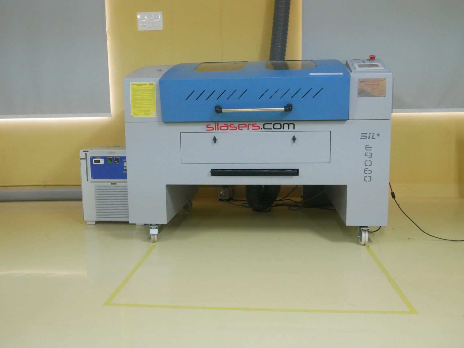
Machine Overview — SIL9060 Laser Cutter
The SIL9060 is an industrial grade CO₂ laser cutting and engraving machine designed for high-precision work across materials such as wood, acrylic, MDF, leather, paper, and textiles. With a spacious 900 × 600 mm working area and a powerful sealed glass CO₂ laser tube, it offers accurate cutting and engraving performance for educational, industrial, and prototyping applications.
Key Features
- 1. Industrial grade CO₂ laser cutting and engraving system
- 2. Spacious 900 × 600 mm working area suitable for medium-sized projects
- 3. Supports multiple file formats such as DXF, AI, PLT, BMP, JPG, and PNG
- 4. Adjustable power levels (typically 60W, 80W, or 100W)
- 5. Water-cooled CO₂ sealed glass laser tube for consistent performance
- 6. Equipped with a red-dot pointer for accurate job alignment
- 7. Exhaust and ventilation system for smoke and fume extraction
- 8. Offline USB control capability for easy workflow integration
Technical Specifications
| Specification | Details |
|---|---|
| Work Area | 900 × 600 mm |
| Laser Power | 60 W / 80 W / 100 W (depending on configuration) |
| Laser Type | CO₂ Sealed Glass Tube |
| Cooling Method | Water Cooling |
| Cutting Speed | Up to ~48,000 mm/min |
| Engraving Speed | Up to ~64,000 mm/min |
| Positioning Accuracy | < 0.025 mm (in some versions) |
| Supported File Formats | DXF, AI, PLT, BMP, JPG, PNG |
| Typical Materials | Wood, MDF, Acrylic, Leather, Paper, Fabric, etc. |
| Operating Voltage | AC 230V ± 10% |
Key Advantages & Considerations
- Large working area enables versatile material processing for Fab Lab projects.
- Compatible with multiple file formats and CAD tools (AutoCAD, Fusion 360, etc.).
- High cutting and engraving precision suitable for press-fit and design experiments.
- Requires proper air assist, ventilation, and cooling maintenance for safe operation.
- Ensure the nozzle focus distance (≈8 mm) for optimal cutting results.
Reference Links
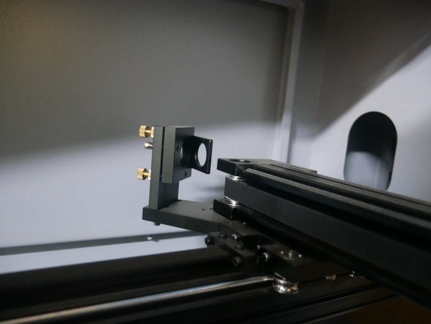
4.1 Focus Adjustment
- Focused the laser head using the focusing gauge for accurate distance between lens and material.
- Correct focusing ensures precision for both engraving and cutting.
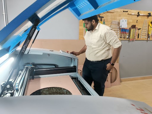
4.2 Origin and Alignment
- Set the origin point (X, Y, Z) manually from the machine panel.
- Checked the material alignment using the bed grid for straight cuts.
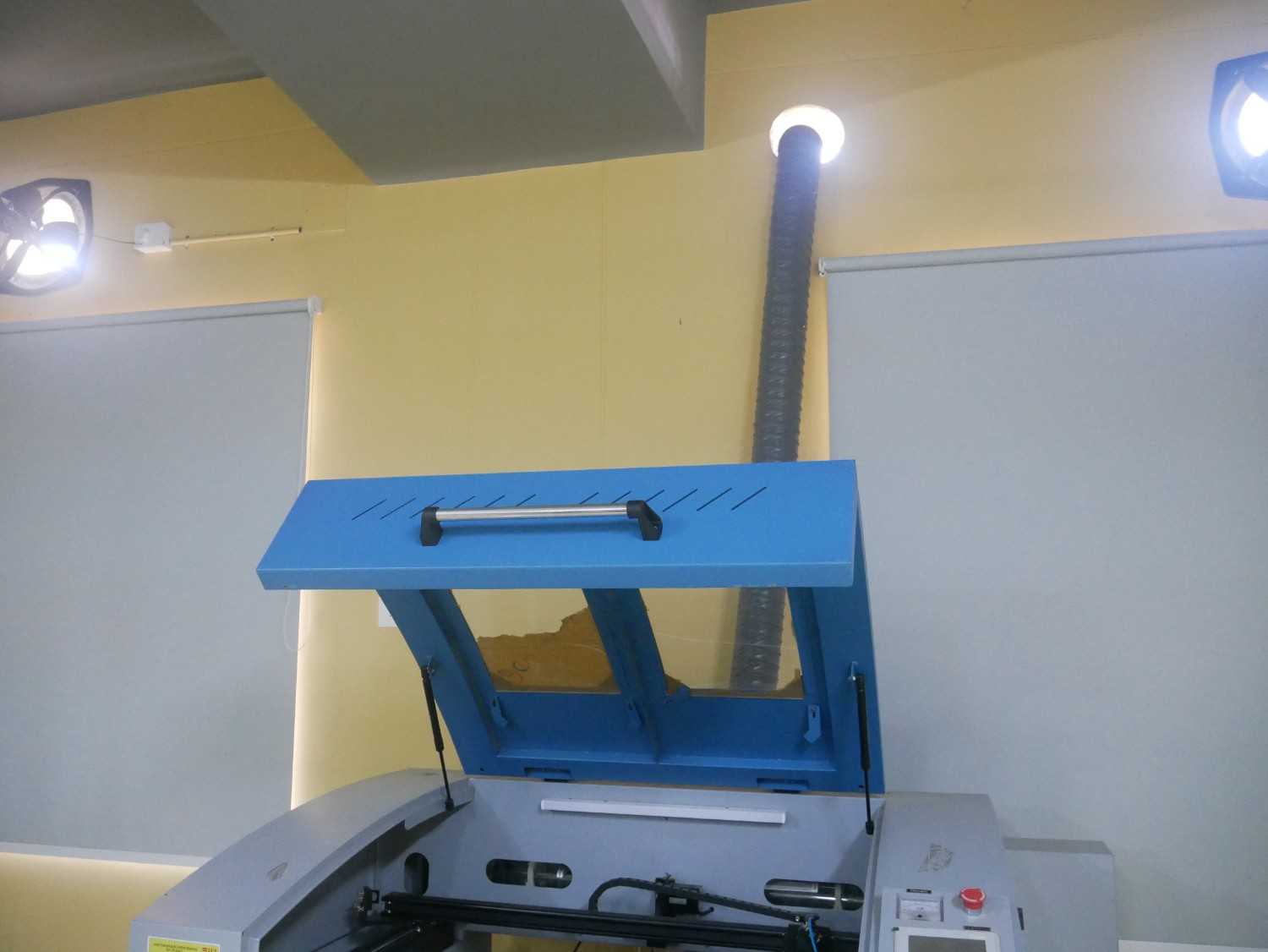
4.3 Air Assist and Exhaust
- Air assist enabled to prevent burning and achieve clean edges.
- Exhaust system turned on for smoke removal and better visibility.
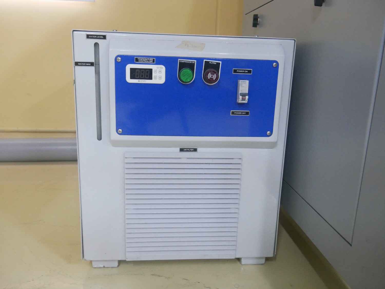
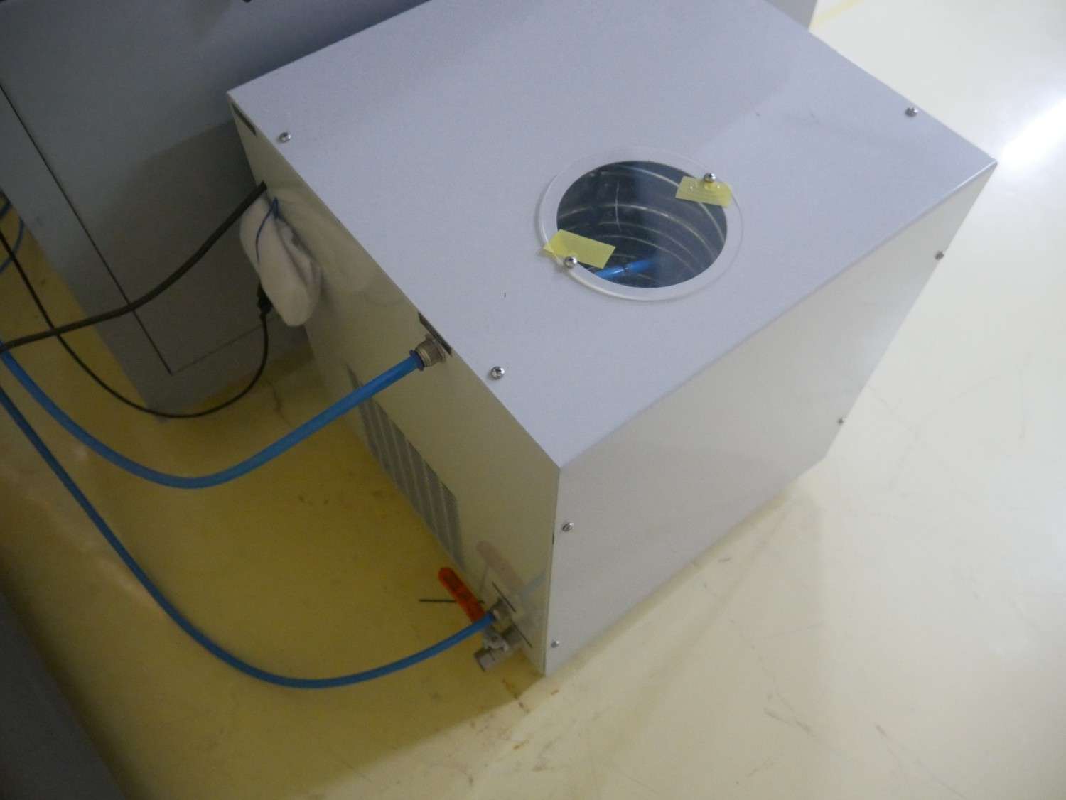
4.4 Cooling System
- Cooling system turned on to maintain a stable temperature.
- Water flow checked to ensure proper heat dissipation.
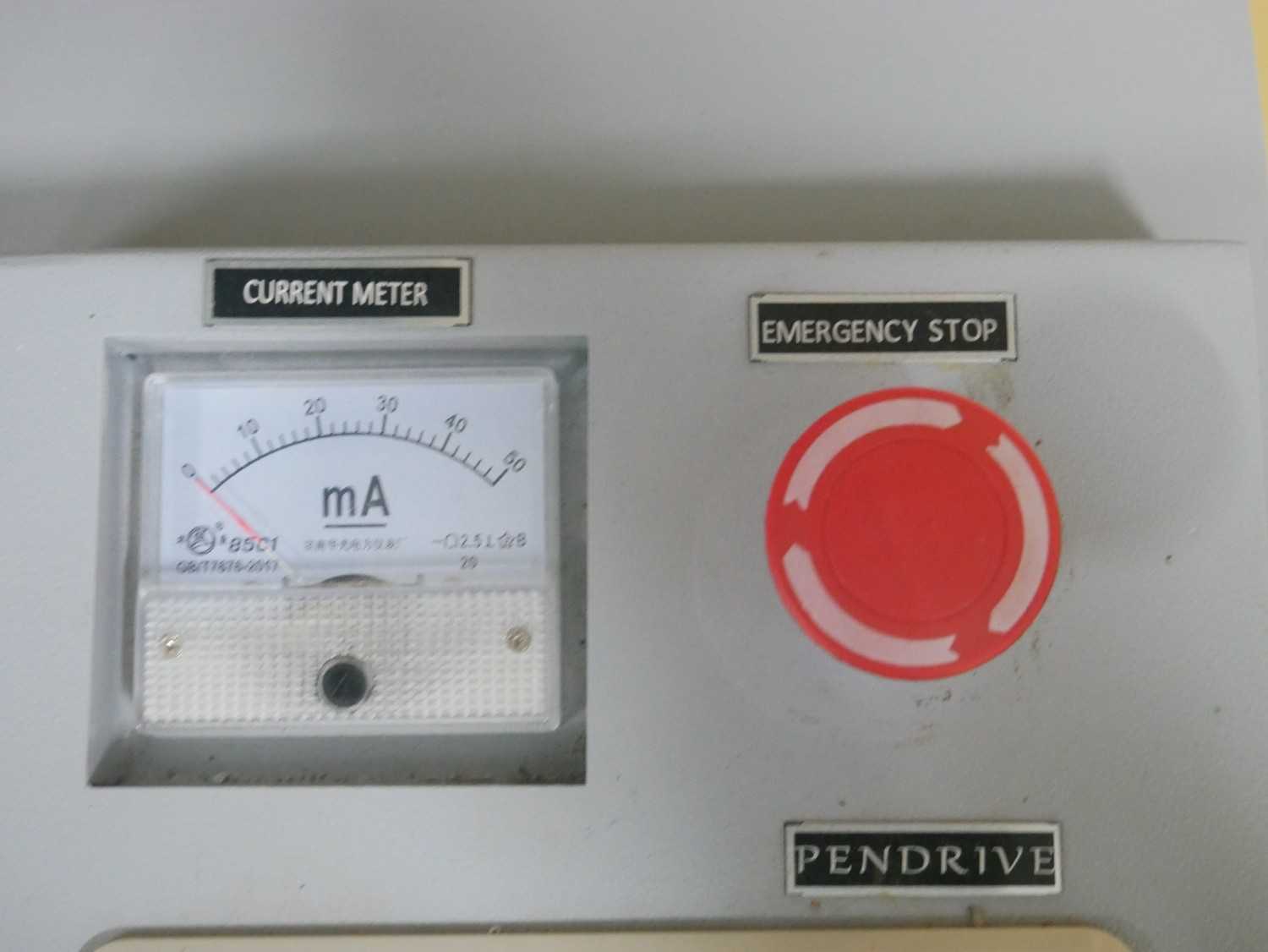
4.5 Emergency Stop
- Emergency stop button pressed to immediately halt the laser cutting process.
- Button functionality tested to ensure prompt response in case of emergency.
5. Kerf Measurement
5.1 Procedure
Using LaserCAD software for sending the design to the Laser machine
Cutting Designed files for measurement
Measuring the Files for the Kerf Measurement in both MDF and Acrylic materials
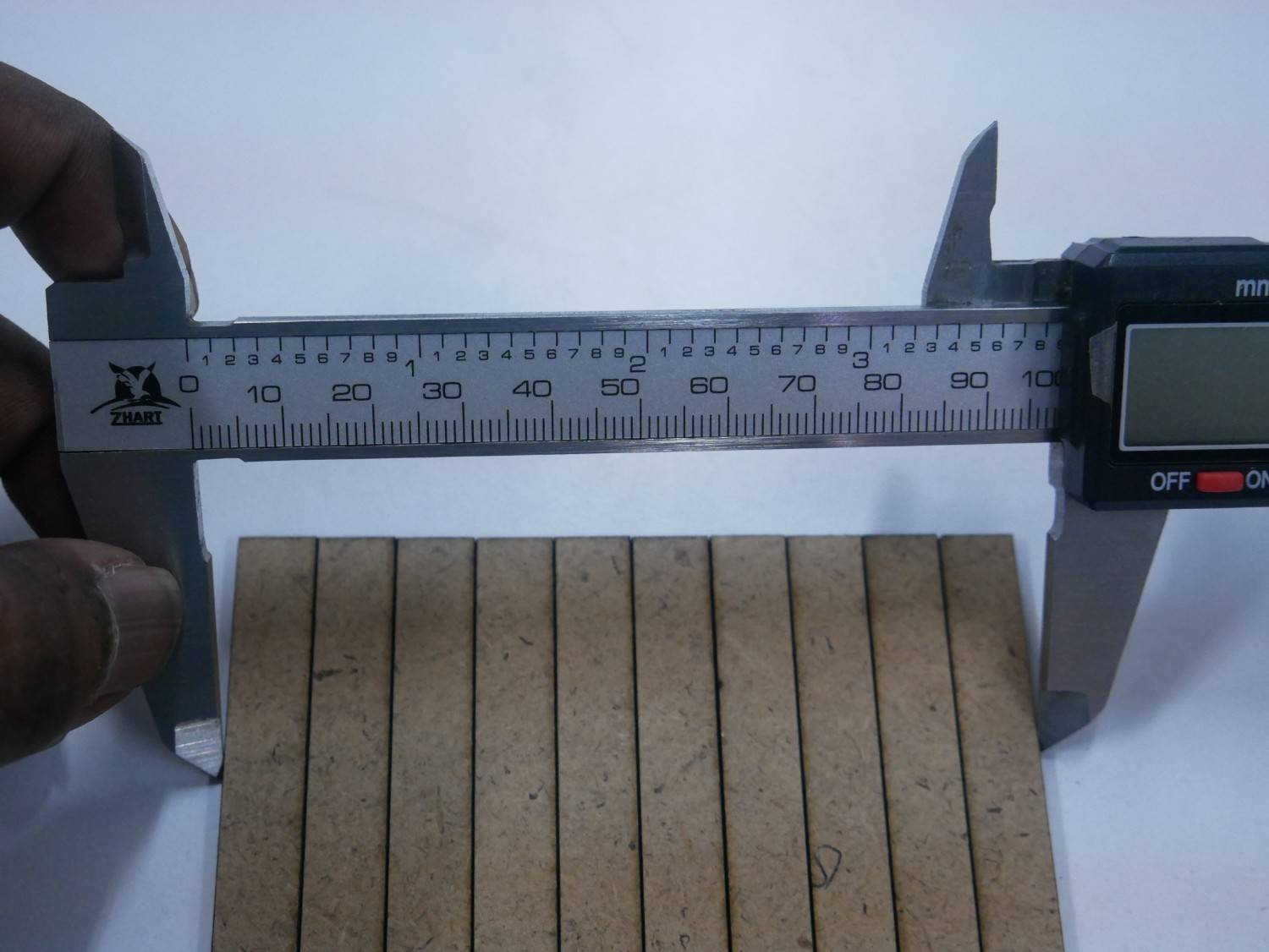
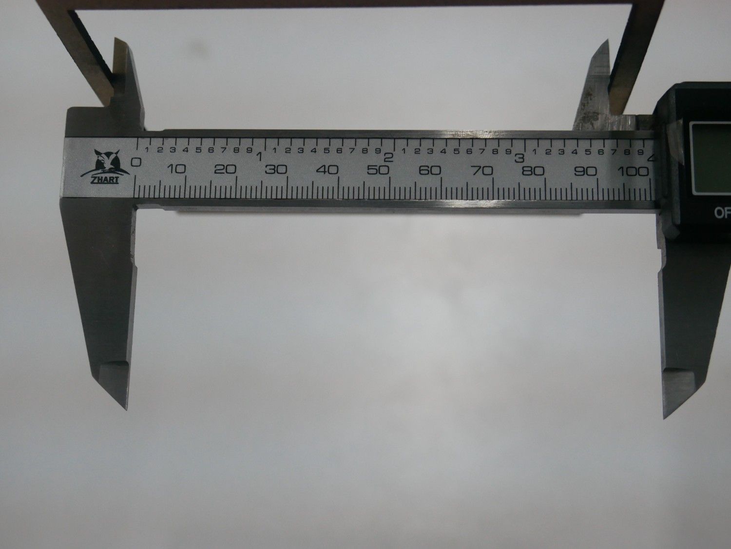
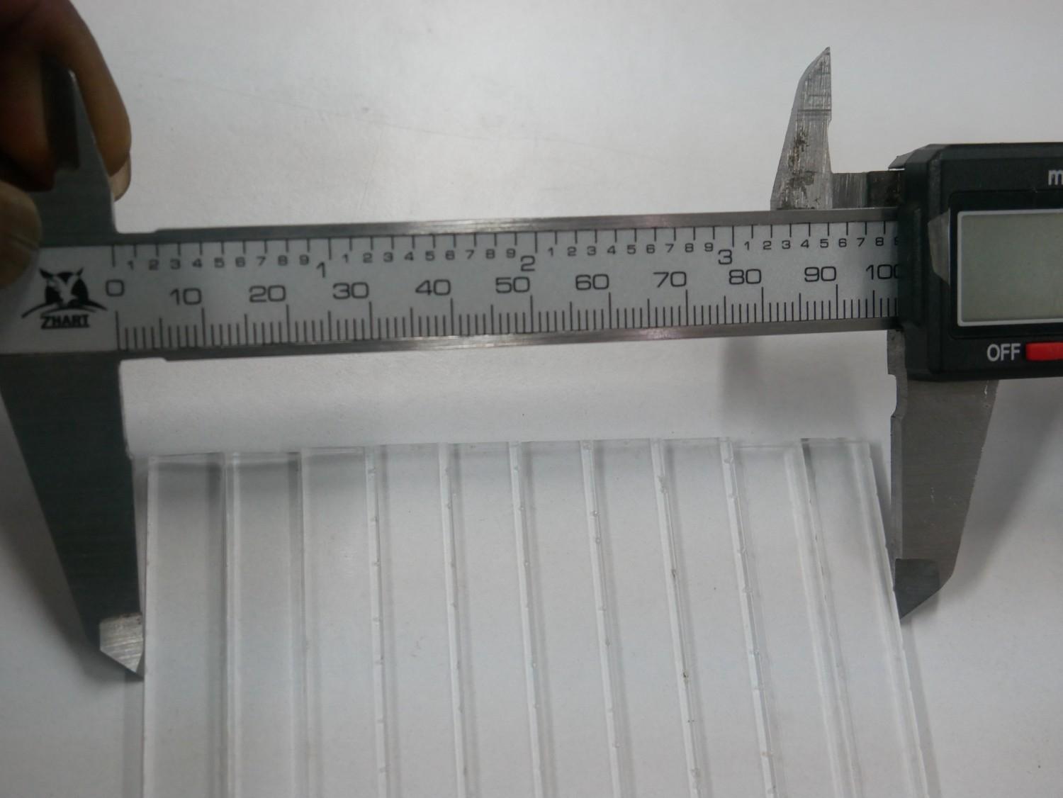
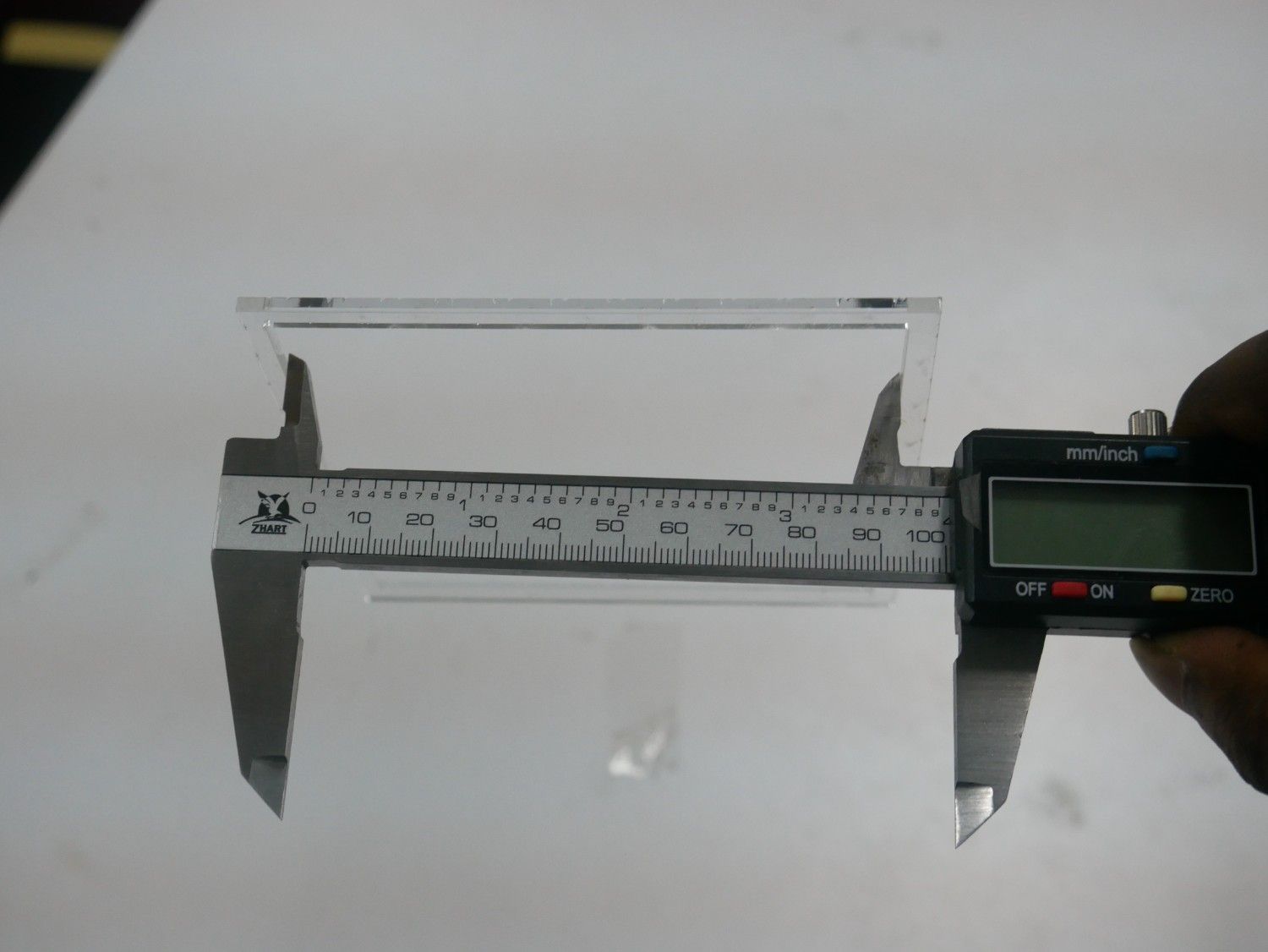
5.2 Results
| Material | Designed Size | Measured Slot (mm) | Measured Piece (mm) | Kerf (mm) |
|---|---|---|---|---|
| MDF | 100 × 100 | 100.30 | 99.70 | 0.30 |
| Acrylic | 100 × 100 | 100.25 | 99.75 | 0.25 |
6. Safety Measures
- Always wear protective glasses during operation.
- Never open the laser lid while cutting.
- Keep the exhaust and air assist active.
- Do not cut PVC or unknown plastics (toxic fumes).
- Check material flatness and lens focus before starting each job.
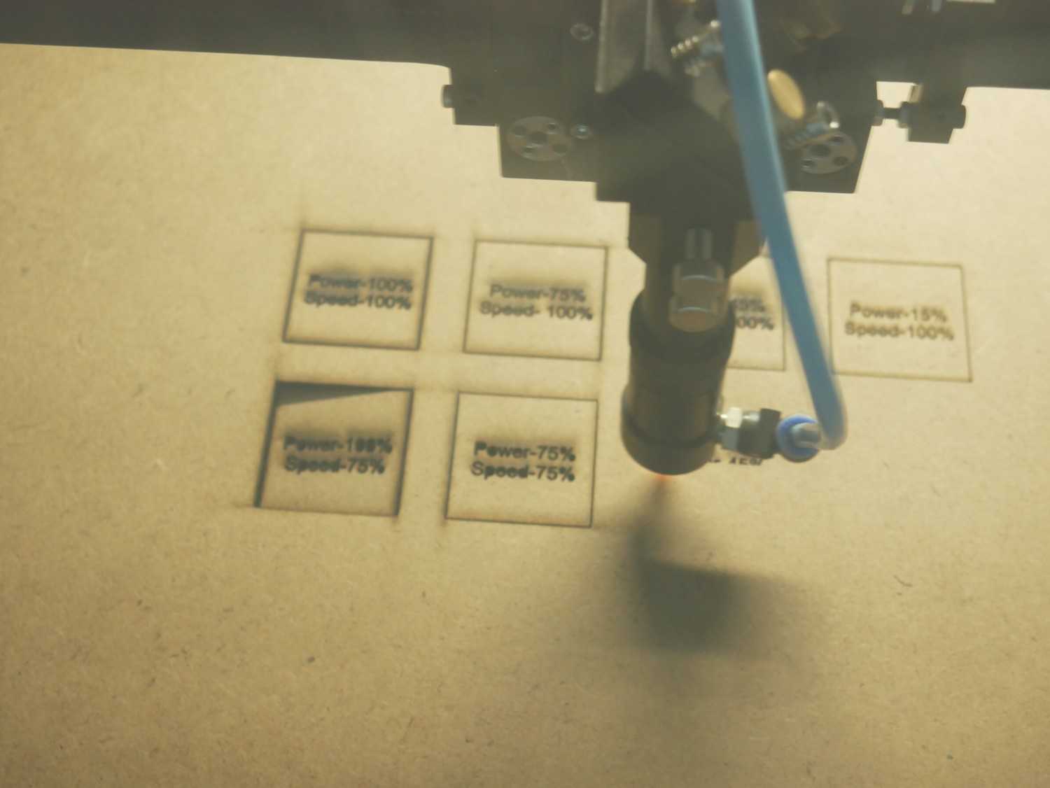
7. Computer Controlled Cutting - Power vs Speed Test
We tested how laser cutting power and speed impact the cutting and engraving quality when adjusted relative to each other.
The experiment was conducted using two different materials: 2 mm MDF board and 2 mm Acrylic sheet.
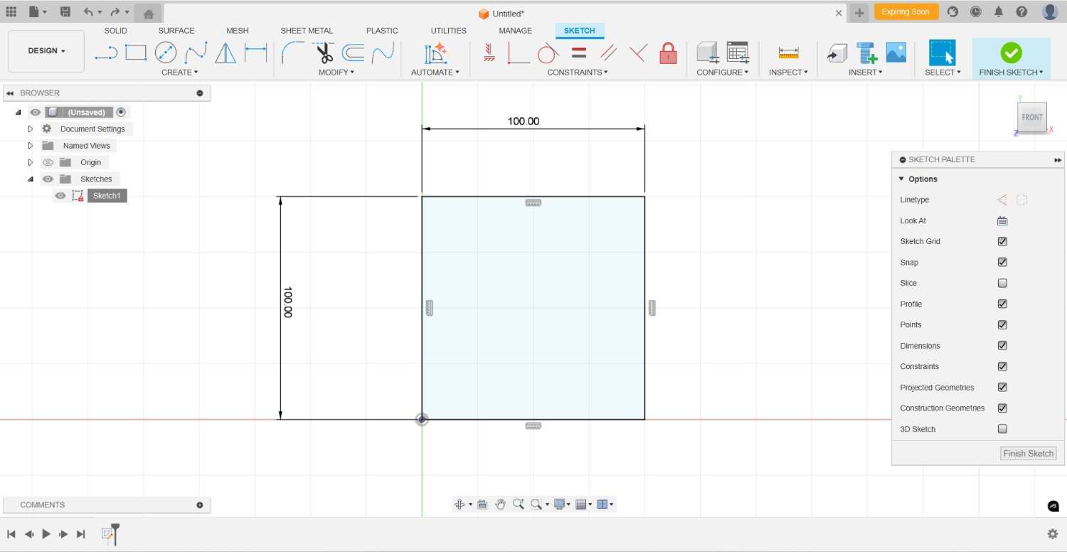
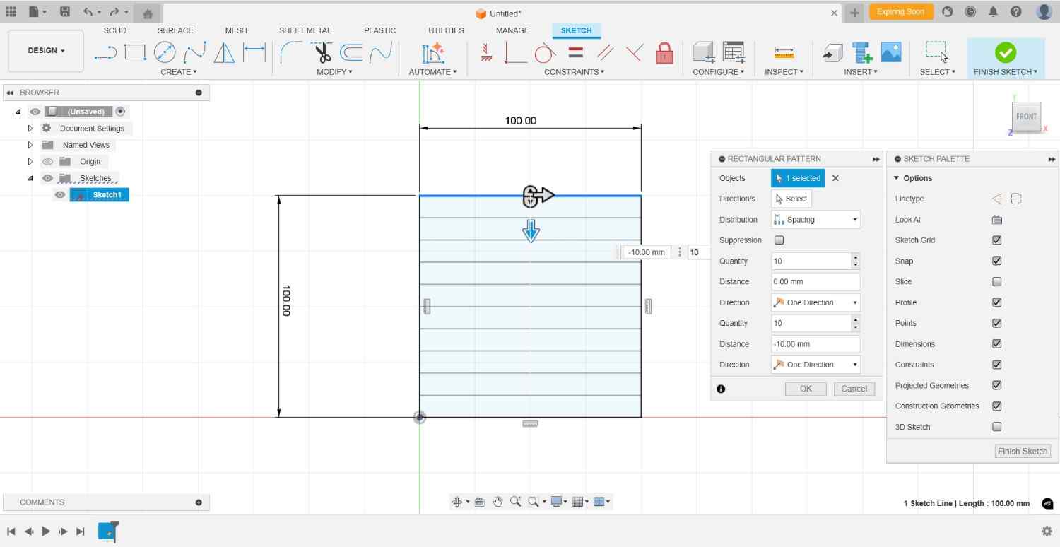
7.1 2D Design in Fusion 360
For the 2D design, we used Fusion 360.
- Created a new sketch and drew one rectangle with set dimensions.
- Used the Rectangular Pattern option to create 4 rows and 4 columns.
- Added text using the Text Tool to label each box with power and speed percentages.
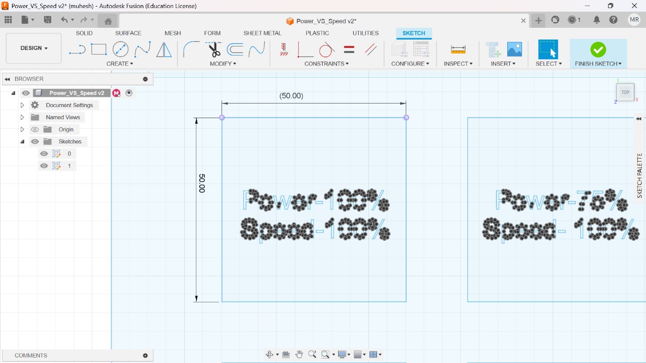
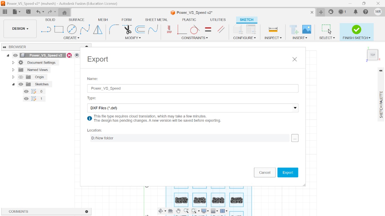
After completing the design, it was exported in DXF format for laser cutting.
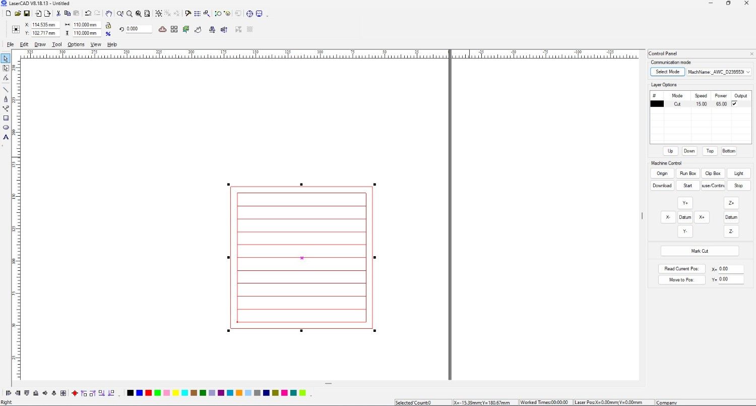
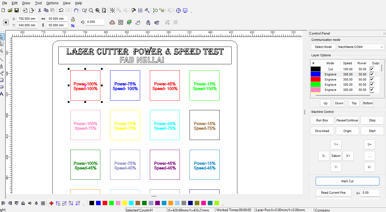
7.2 Importing into LaserCAD
The DXF file was imported into the LaserCAD software.
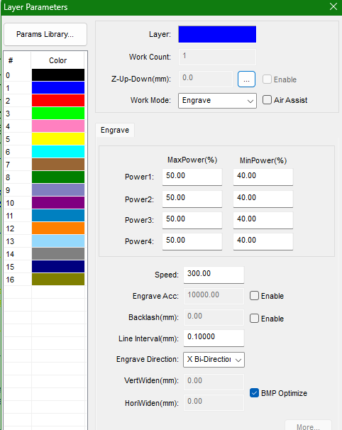
- Different colours were used to distinguish cutting, engraving, and non-operation paths.
- The rectangle boxes were assigned for cutting and the text areas for engraving.
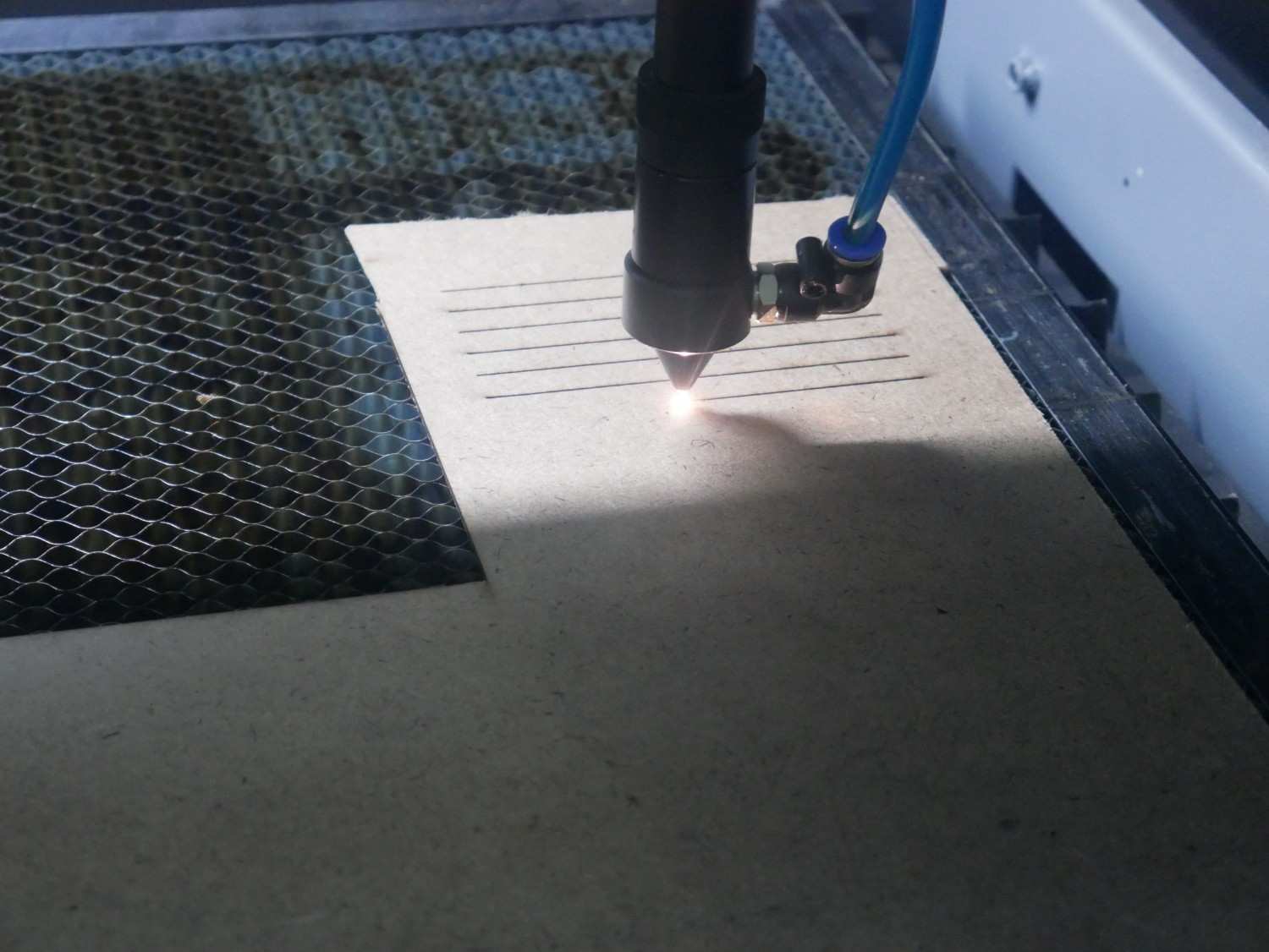
7.3 Cutting Process
- Set the origin of the nozzle to the required start position.
- Checked the workspace boundaries to ensure enough space for cutting.
- Closed the safety door and ensured the exhaust was turned ON to remove burnt gases.
- Finally, started the laser machine and ensured both laser and exhaust systems were functioning properly.
7.4 MDF (3 mm) Test Results
| Test No | Power (%) | Speed (%) | Frequency (Hz) | Result | Remarks |
|---|---|---|---|---|---|
| 1 | 50 | 100 | 500 | Not Cut | Power too low |
| 2 | 60 | 60 | 1000 | Partial Cut | Slight burn |
| 3 | 70 | 40 | 1000 | Perfect Cut | Optimal |
| 4 | 80 | 30 | 1000 | Burnt Edge | Excess power |
Optimal Setting: Power = 70%, Speed = 40%, Frequency = 1000 Hz
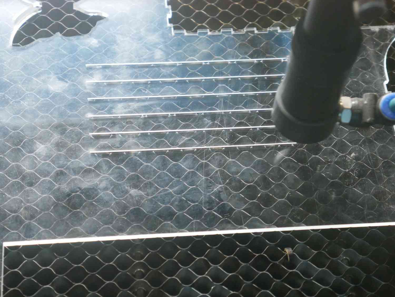
7.5 Acrylic (3 mm) Test Results
| Test No | Power (%) | Speed (%) | Frequency (Hz) | Result | Remarks |
|---|---|---|---|---|---|
| 1 | 40 | 80 | 500 | Engraved Only | Low Power |
| 2 | 50 | 60 | 1000 | Partial Cut | Not Through |
| 3 | 60 | 40 | 1000 | Perfect Cut | Clean Edge |
| 4 | 70 | 30 | 1000 | Melting | Excess Power |
Optimal Setting: Power = 60%, Speed = 40%, Frequency = 1000 Hz
8. Summary
Through this group activity, we learned to:
- Operate and calibrate the laser cutter safely
- Optimize cutting and engraving parameters
- Measure and compensate for kerf
- Determine ideal press-fit clearances
- Apply results to future individual project designs
9. Design and Test Patterns
9.1 Test File
A test file was designed consisting of:
- 1. Multiple squares and circles to test kerf and fit.
- 2. Gradient text for engraving power variation.
- 3. Parameter labels (speed, power) for reference.
File Format Used: .DXF / .SVG
Kerf Test.dxfPower Test.dxf