Week 9 : Input Devices
This week is meant to build a better and more developed understanding of electronics with input devices. For our individual assignment, we need to add a sensor to a microcontroller board we designed and read it. As well for our group assignment, we need to probe an input device’s analog and digital signals.
Input Device with Microcontroller Board
Ideally, I would be testing and connecting a motion sensor since that is one of the main inputs I intend on using for my final project, but I still do not have one in hand at the moment. Instead, I will be using a roller switch, which is similar in functionality. This will demonstrate, fully on and off, versus an input with ranges in values that vary at different levels of intensities.
 - The PCB board I designed and milled last week already has traces made to account for two inputs and two outputs. Taking into account lessons from the previous week, I quickly noticed the wiring for the switch was not arranged in the same order as my traces. Instead of pulling the wiring apart on the switch, I just used additional wires as an extension, which then allowed me to plug into my board easily in whatever arrangement is needed.
- I wanted to be able to see an obvious physical cue that the input works when activated along with seeing a readout when probed. To do so, I continued to build off my previous work from last week using code to move a servo motor. With the courtesy of Chat GPT, I provided my existing code and asked to have the code work with using a roller switch to activate the servo.
#include < Servo.h >

        Servo myServo;
        int var = 0;
        const int switchPin = D2;  // Define the switch pin
        const int servoPin = D8;   // Define the servo pin

        void setup() {
          pinMode(switchPin, INPUT_PULLUP);  // Set switch as input with pull-up resistor
          myServo.attach(servoPin, 600, 2400);
        }

        void loop() {
          if (digitalRead(switchPin) == LOW) {  // Check if switch is pressed
            var = 0;  // Reset var to allow movement

            while (var < 4) {
              // Move from 0° to 90°
              for (int pos = 0; pos <= 90; pos += 1) {
                myServo.write(pos);
                delay(10);
              }

              // Move back from 90° to 0°
              for (int pos = 90; pos >= 0; pos -= 1) {
                myServo.write(pos);
                delay(10);
              }

              var++;
            }
          } else {
            myServo.write(0);  // Keep servo at 0° when switch is not pressed
          }
        }
To see the full Chat GPT conversation, click on this LINK
- I adjusted the code to reflect the pins I have being used by the switch, verified it, and uploaded it to the RP2040.
- When the button is clicked on the switch, you can see the servo moves as written in the code. You can also see when probed with a multimeter, the instance the button is clicked it reads high voltage and immediately goes back to a low, no flowing current, voltage reading.
Group Assignment
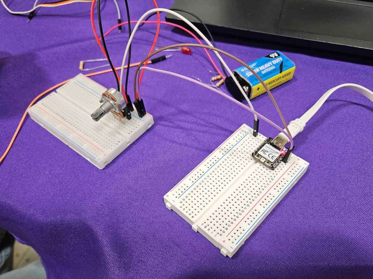
For our group assignment we decided to probe a potentiometer. We wanted to test an input different from what we are both using in our final projects, where we could learn and see a different range of readings from what we are working with individually.
- To run a potentiometer, the signal needs to be connected through an analog pinout of the RP2040 micro controller. Since we both designed and milled boards that do not interact with analog pins, we decided to use breadboards. Utilizing the breadboards, we used wires to connect our power, ground, and signal to the RP2040.
- We used Chat GPT to write code and made sure to modify the code corresponding with the appropriate pinout the potentiometer is wired to. We also found that you can include a serial monitor in Arduino. From here we verified and uploaded the code to the RP2040.
#define POT_PIN A0  // Connect the middle pin of the potentiometer to A0

        void setup() {
            Serial.begin(115200);
        }

        void loop() {
            int rawValue = analogRead(POT_PIN);  // Read the raw analog value (0-1023)
            float voltage = rawValue * (3.3 / 1023.0);  // Convert to voltage (3.3V max)

            Serial.print("Raw Value: ");
            Serial.print(rawValue);
            Serial.print(" | Voltage: ");
            Serial.print(voltage, 2);
            Serial.println("V");

            delay(500);  // Wait half a second before reading again
        }
To see the full Chat GPT conversation, click on this LINK
- While there are no physical cues of it working, we got a reading of the voltage current with the multimeter as well as the serial monitor. When turning the dial, we were able to see the voltage increase and decrease and at different rates depending the direction and speed the dial was turned. It was also neat to be able to test and compare the reads of the multimeter to the serial monitor. For our findings, they were fairly accurate and comparable. We noticed at times there were slight differences in the voltage read out when probing with the multimeter vs without probing by about .05v. This makes sense since we are slightly interfering with the current when introducing the multimeter.
