Week 7 : Computer-Controlled Machining
This week is BIG week. BIG projects, with BIG machines, with even BIGGER ways of messing up! Our goal was to make (design, mill, and assemble) something large on the meter scale. So naturally, for our group assignment, our goal was to go through labs safety training for the CNC and test runout, alignment, fixturing, speeds, feeds, materials, and toolpaths for our CNC.
Buildign Something BIG with the CNC
For this week’s project, I chose a design based off a few work arounds I needed to consider and even with the amount of preventative planning, I still had challenges to face. At AMRoC Fab Lab we currently didn’t have a wood bit available in the shop and we have a decent amount of scrap polycarbonate, so the chosen material would be polycarbonate. Also, our CNCs in the shop are on the smaller side, the largest with a cutting size of 39inx23in. This means I would need to divide my file into more pieces and consider connections.
I decided to make a standing cutout structure of the Forest Spirit from the Studio Ghibli film Princess Mononoke. A friend of mine will be getting married and she will be having décor that is Studio Ghibli themed. This Forest Spirit is intended to be uses in a photobooth scene.- To create the files, since it is more of an organic but distinct design, I wanted to draw it out. I used Photoshop and a Wacom tablet to draw the main design and shapes.
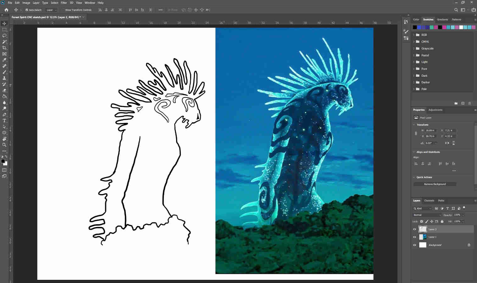
- I used two different colors for my own indication of which pieces I want to cut all the way through versus which I want to be pockets.

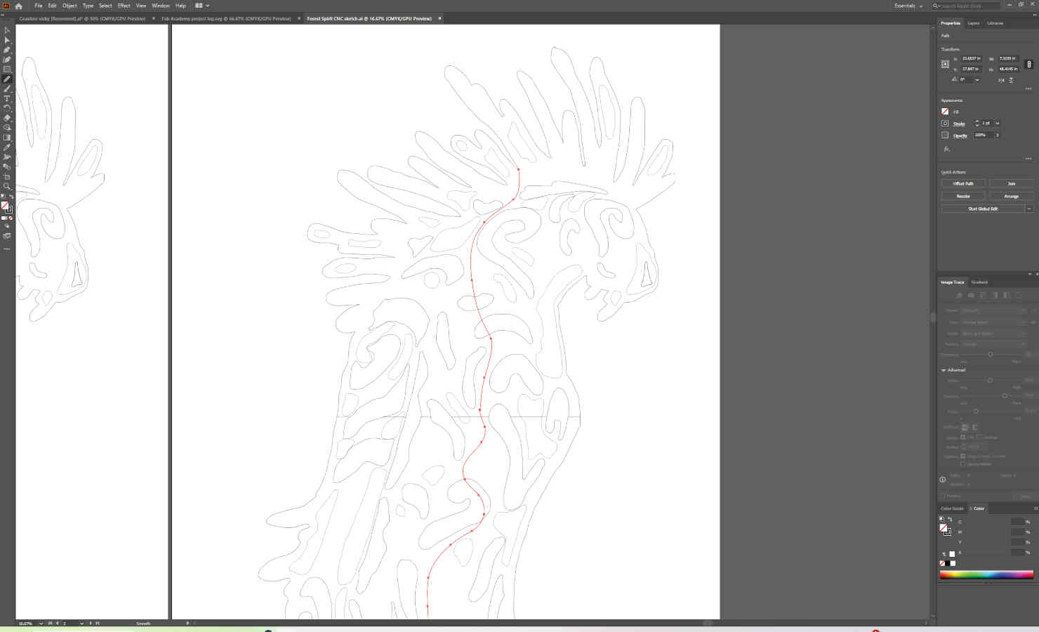
- Then I transferred the photoshop file to Illustrator. I imaged traced the design to turn it into a vector file. I cleaned up edges and imperfections.
- I sized the design to the desired dimensions. Here is where I divided the design into four separate pieces. Once I divided the pieces and cleaned up what are attached pieces and split up pieces, I added in the slot connections.
- I measured the thickness of the material and made the slots accordingly. We will add in parameters after when we transfer the file into Onshape or Fusion360. I added in dogboning.
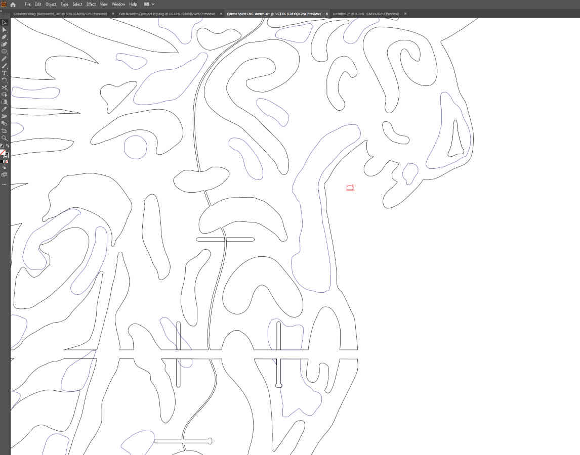
- Once I completed the file in Illustrator, I exported the files as DWG files to open them into Onshape.
- In Onshape, open a sketch page and choose the Top face. There is a button in the top menu bar to import a DXF or DWG file. Here is where you import the file.
- The file will show up on the sketch page. Extrude the main face/surface to the thickness of the material.
- To create different thicknesses within the file (which shapes I want as pockets, pieces that are thinner but not cut all the way through), create a second extrusion. Click on all the faces(shapes) you want to be the same pocket thickness and type in the desired depth.
- Now the file is set to the correct setting. We need to open our file in Kirimoto to set up the toolpaths and other CNC settings.
- Click the plus sign at the bottom left of Onshape and go to applications where you can connect to Kirimoto.
- In Kirimoto, the operations list is to the right menu bar. You choose a toolpath (like pocket, trace, rough, etc.) Here you set the spindle rate, feed rate, plunge rate and other specs depending on which toolpath you are working in.
- Set the rates and then click the select button to click on the corresponding parts on the 3D file. If you are doing a trace cut, that cuts completely through the material, you want to select the bottom edge of the file material verses the top edge of the material. For pockets, you select the inset surface and not the edges of the file.
- Once you select and set up all your paths, you can preview the toolpath both in “slice” where you can see the layers and animation with a video running it intended cuts.
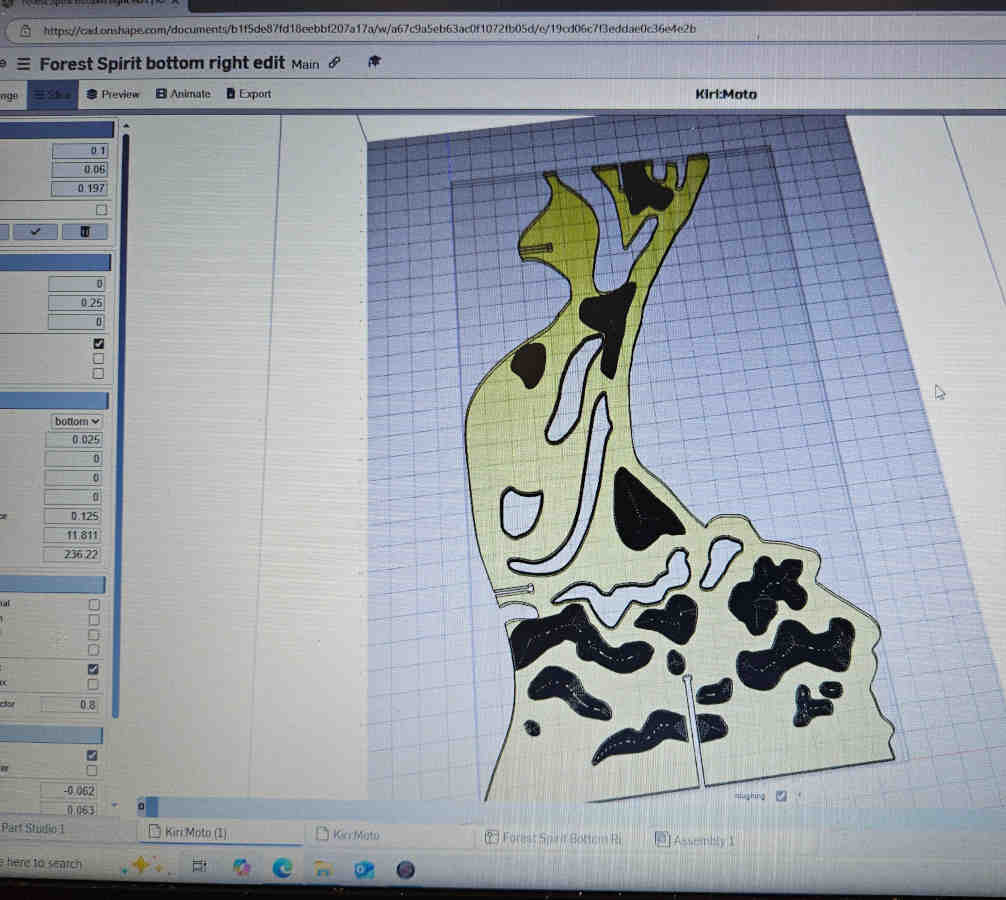
- Now that everything is ready to go, save your file as a gcode.
-Open your CAM software. At our shop for our machines we use Mach3Mill. Load your gcode into the software.
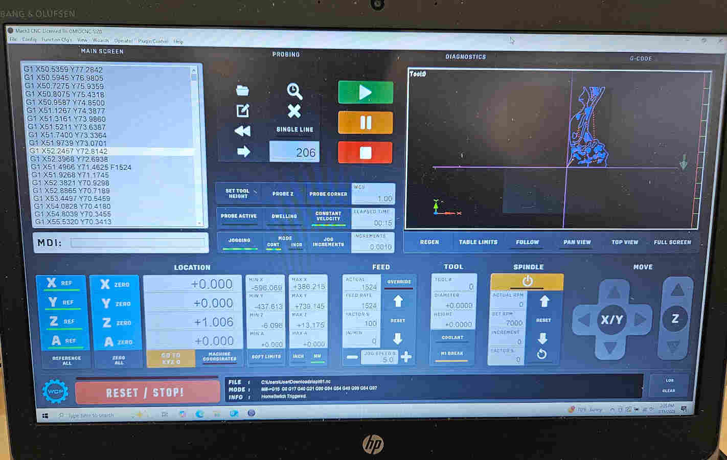
- Before running any files, you are going to want to make sure the spindle/bit is out of the way of you loading your material onto the CNC bed.
- To fix the material to the bed, we use brass screws to screw our material into the spoil board. Make sure to fasten down all corners of the material so you don’t get material lifting during cutting.
- If the material is fastened down well, then we want to set our Zero for the X, Y, and Z axis.
- With all our previously set code, we should be a to press play and watch the magic happen…SHOULD. When I hit play and it started on the first pocket, it looked very deep on the first pass and was getting instant material build up on the bit and even minor material chipping. The grove was about 1/8in deep when I had set the step down to be.025in. I triple checked and trouble shot everything I could think of. Was the step down set correctly? What about spindle rate? Well that shouldn’t affect the depth of the cut? Its not a down cut. Is the material getting stuck on the bit? Maybe I didn’t set my zero position correctly?
- I started the cut over multiple times and still same result. I was stumped. After hours and actual days I have come to find out it was something simple that I had accounted for but didn’t in a certain aspect. The material was bowed/warped.
- By the time I figured this out, I needed to leave for Miami to get together at Moonlighter Fab Lab to work on next week’s assignment of electronics production week.
- Luckly, while being in Miami I was able to continue working on my CNC project there and cut my project using their CNC. With their CNC we use RhinoCAM. Here we selected which paths are to be pockets and cut throughs. We also set the tool info along with feeds and speeds.
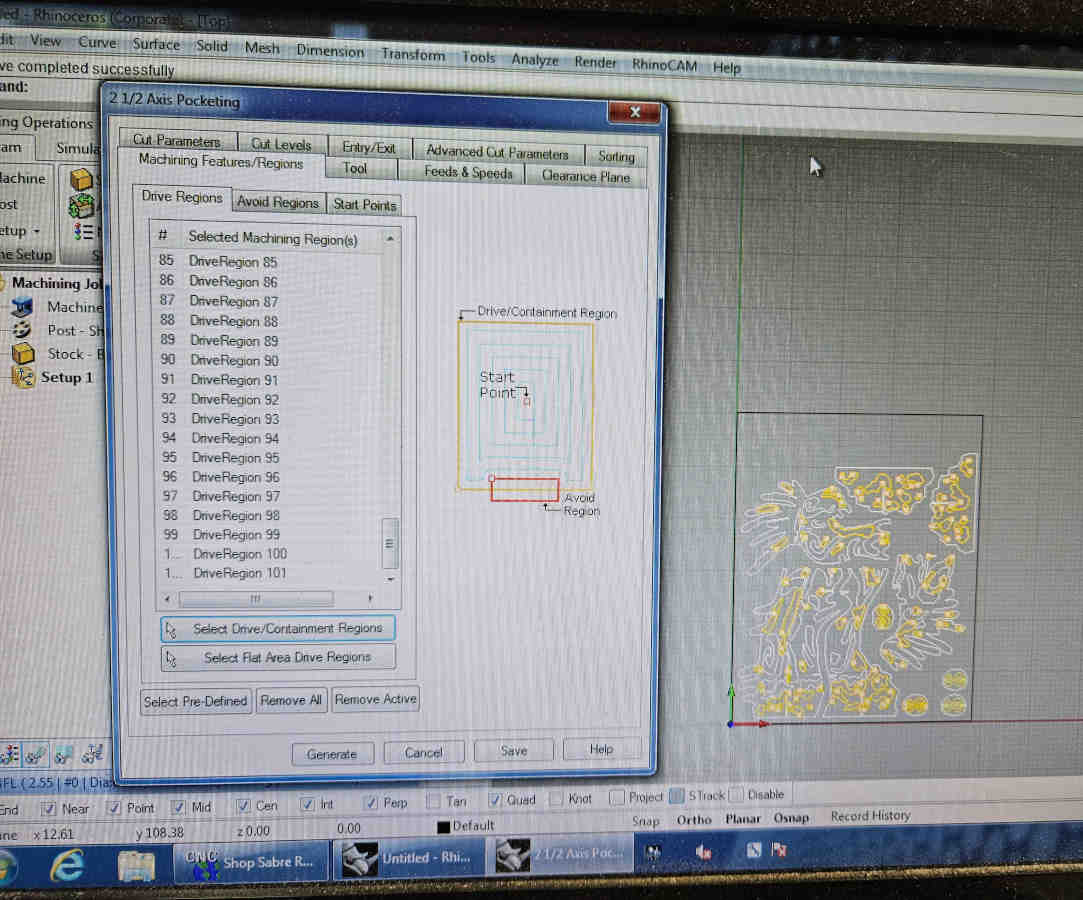
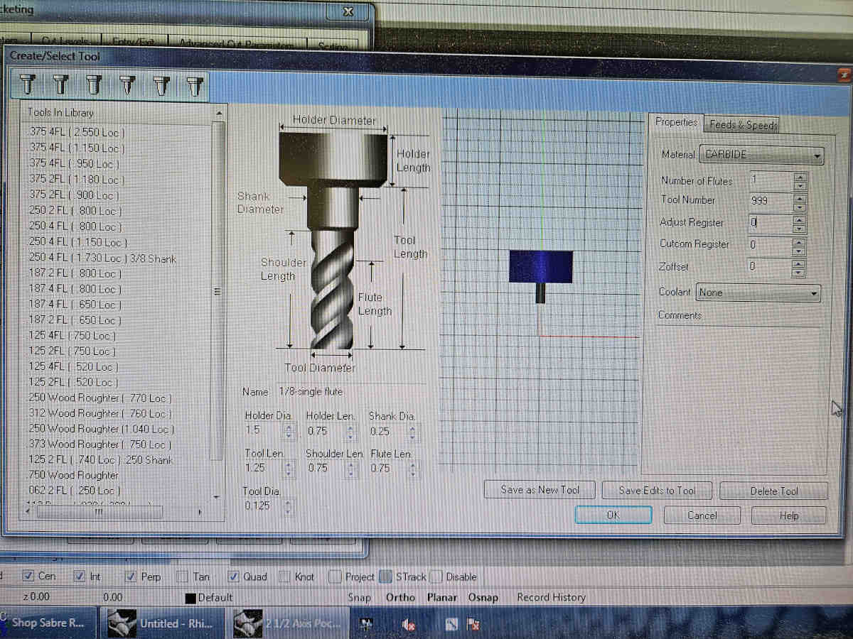
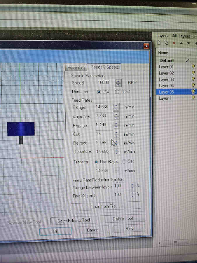
- Five hours of pocketing does take a toll on an already used bit and you will have casualties. Also, even though the leveling of the bed and material were much better here, I still had some areas that didn’t quite cut through all the way and needed some additional persuasion to come apart.
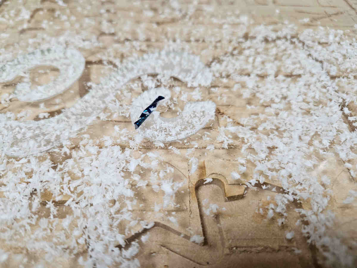
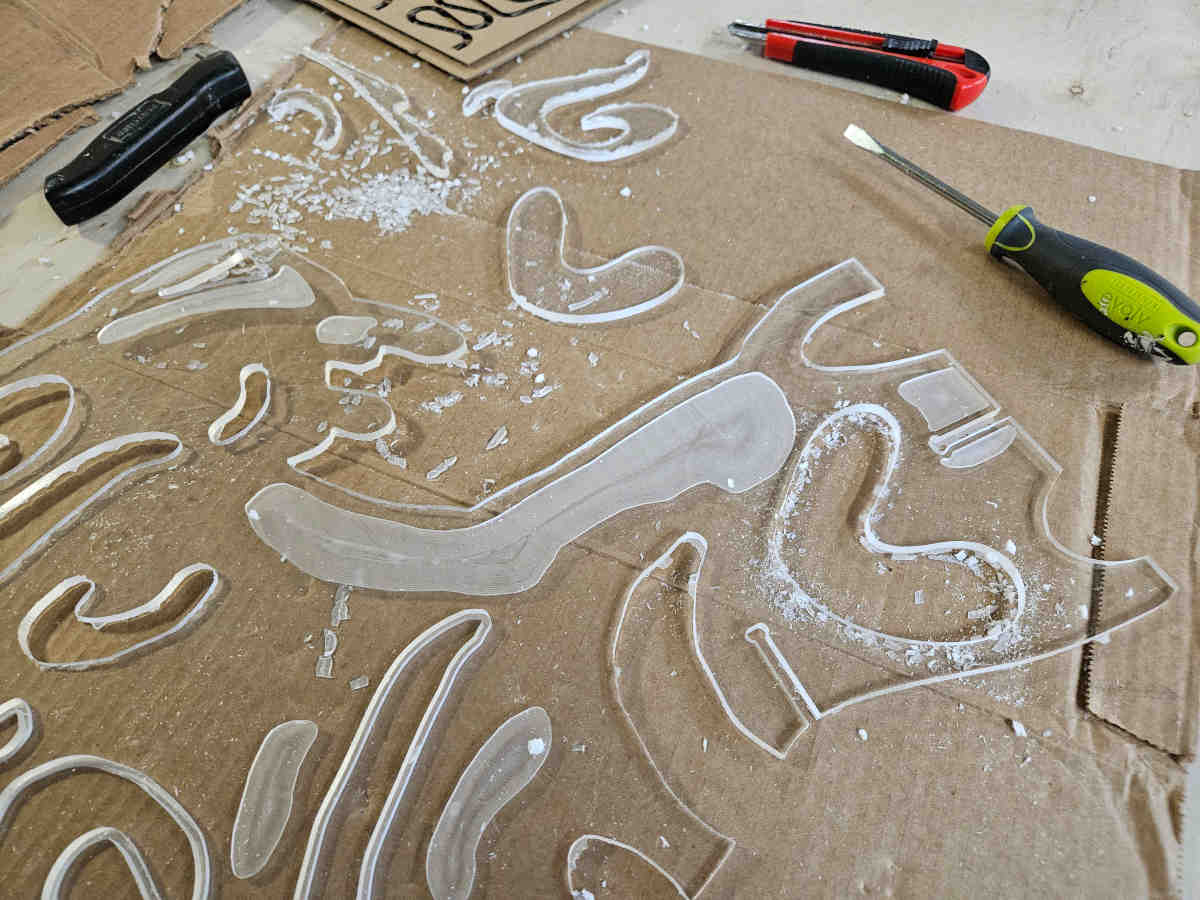
- Another fun learning experience was the machines software algorithm of determined point of entry and exit are not always the best path and seem with my connector pieces. We had to manually change where the point of entry was for those pieces so it would not break off fragile breaking points when exiting the cut.
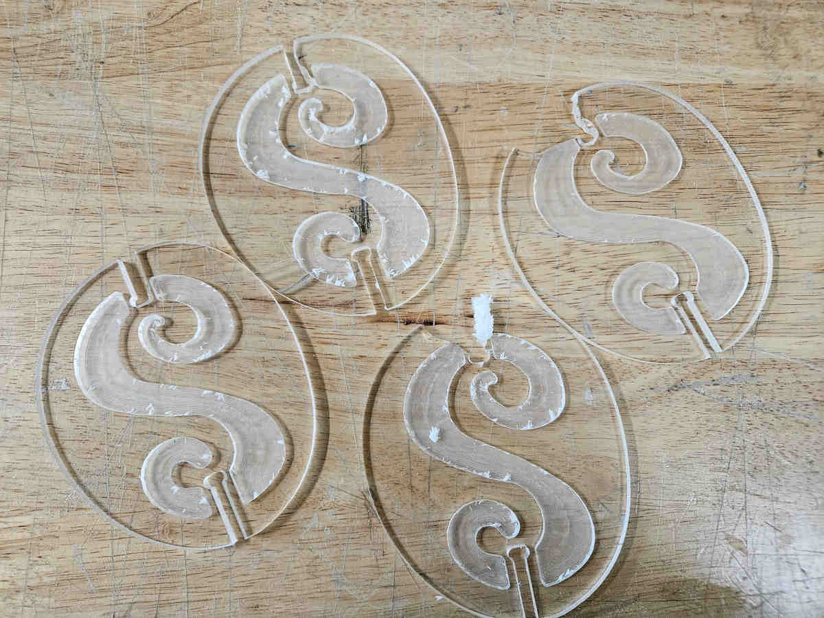
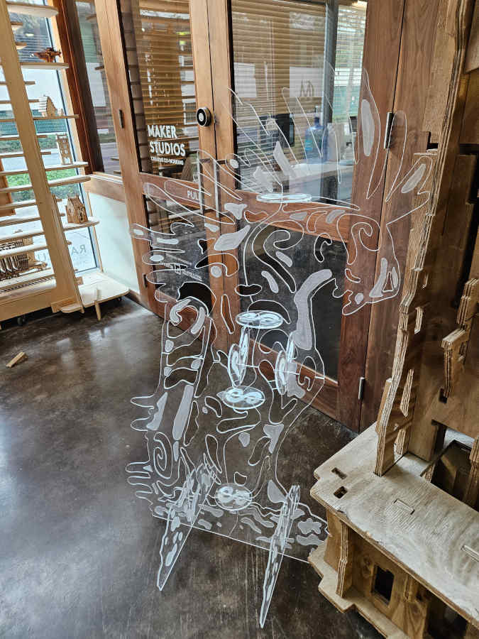
- While having some experience with the CNC in the past, I truly pushed myself with this project and it was a great learning experience, testing and pushing different aspects of what the machine can do. I finally have a (not so perfect) Forest God.
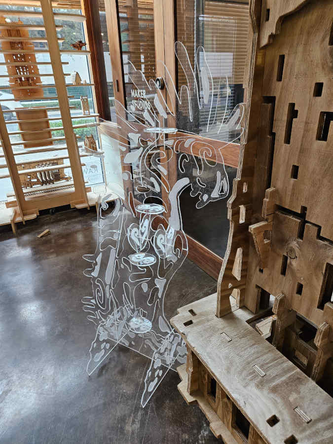
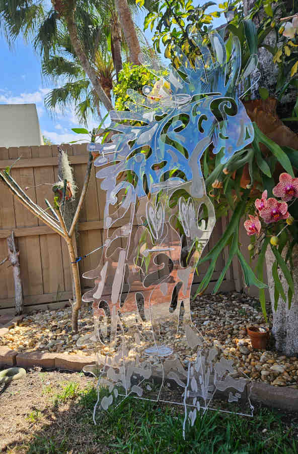
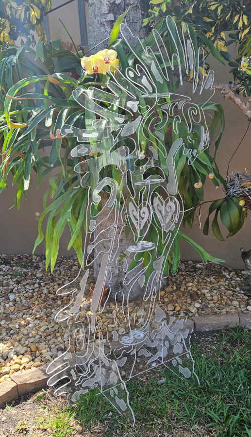
Group Assignment
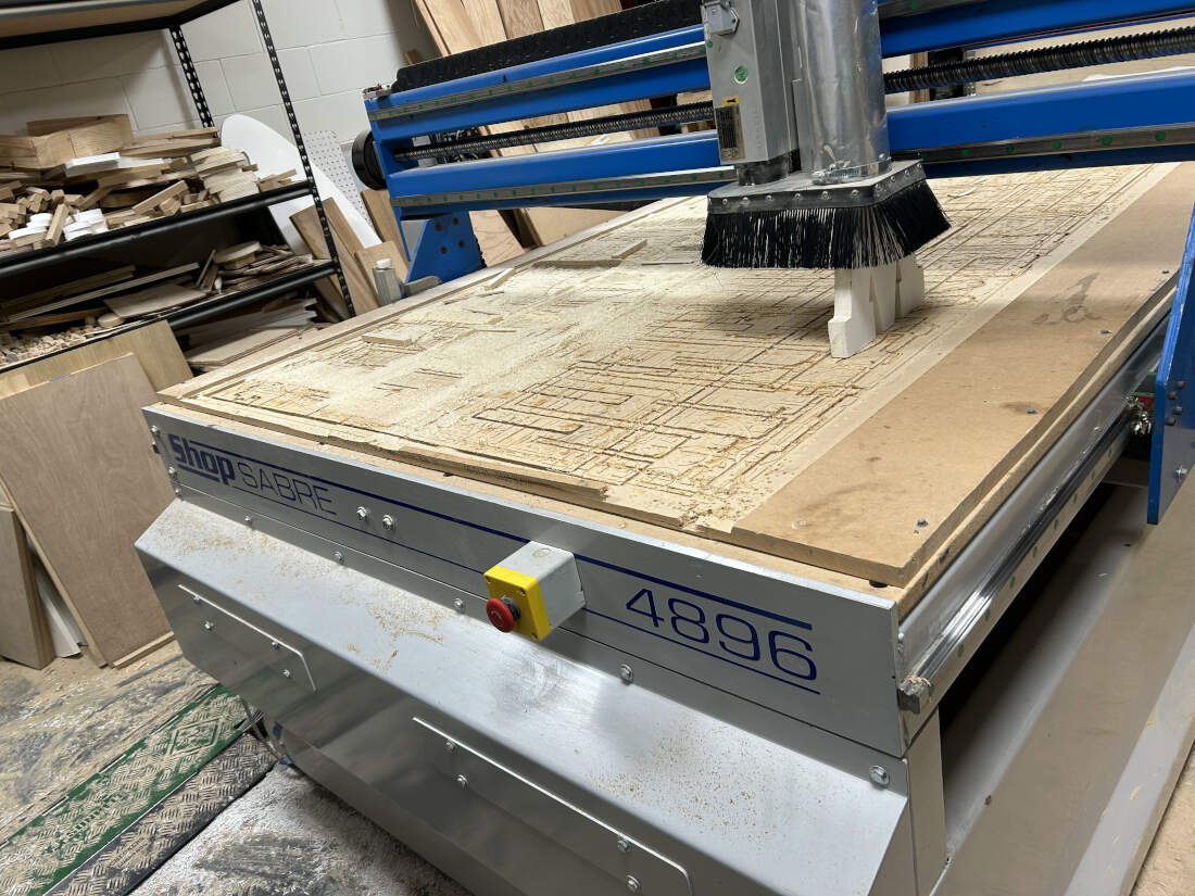
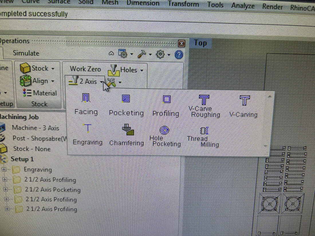
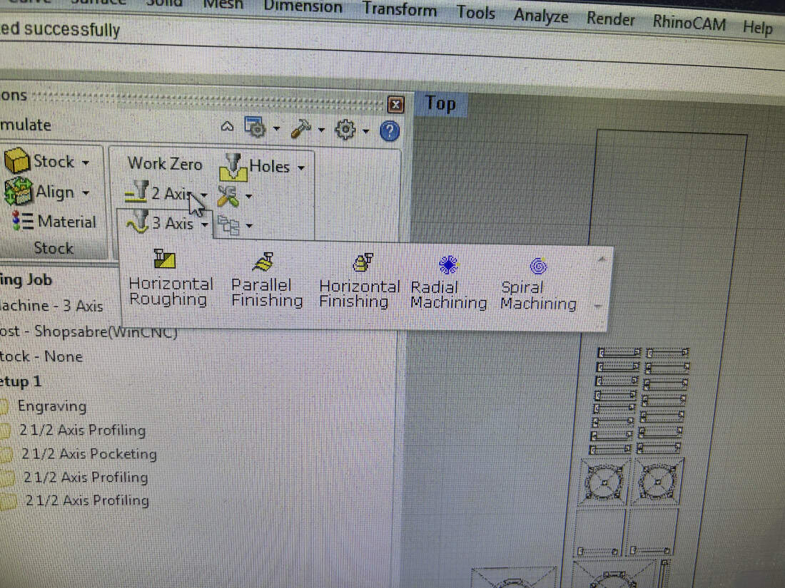
The ShopSabre 4896 is a CNC router with a 48" x 96" work area and 2.5-axis movement. It runs on Shop Sabre Router Controller software using a Windows-based controller. The spindle tops out at 18,000 RPM and is powered by a 9.38 HP motor. We are being tasked with training ourselves on safe operation of the CNC and characterizing its operations and capabilities.
Safety & Use:
- Don’t reach for parts while the machine is on. Use the emergency stop if needed.
- Keep the vacuum on during all cuts.
- Wear safety goggles inside the workshop.
- Kerf size depends on bit size and diameter.
- Inside corners will be round due to the bit shape and bit diameter.
- Use a 2D vector file for profile cuts.
- Use a 3D file type for 3D organic surfaces.
- Avoid designs with overhangs.
Material & Bit Pairings:
- Solid Wood – 2-Flute Endmill
- Plywood – Compression Bit
- MDF – 2-Flute Endmill
- Corrugated Plastics/Cardboard – Corrugated Bit
- Foam – Single-Flute Endmill
- Plastics – Single-Flute Endmill
- Thin Metal Composites – Single-Flute Endmill
Pick the right bit for the material you're cutting.
CNC Operations & Guidelines
2D Operations
- Profiling – Cuts along inner/outer edges of shapes
- Engraving – Adds shallow surface detail
- Pocketing – Clears material inside closed shapes
These operations are the most commonly used within our facility and space.
3D Operations
- Horizontal Roughing – Removes bulk in horizontal layers
- Horizontal Finishing – Refines detail using horizontal toolpaths
- Radial Machining – Radiates toolpaths from a center point, good for circular shapes
- Vertical Roughing – Clears material in vertical passes
- Vertical Finishing – Final vertical pass for fine detail
Design Tips
- Max cut area: 48" x 96"
- Leave a margin to screw stock to the table
- Keep at least 1" between parts to reduce vibration
- No vacuum hold-down—secure your stock manually
- Avoid cutting material over 2" thick or carving deeper than 3.5"
- Split complex designs into multiple parts
CNC Workflow
1. Load your material.
2. Turn on your machine.
3. Turn on the shop vacuum (ours is a ShopFox.)
4. Home the CNC
5. Load the correct bit for the job.
6. Tool height your bit.
7. Zero the Z-axis to your material.
8. Open or import your design file.
9. Program toolpaths using 2D or 3D operations.
10. Export toolpaths as a .NC file.
11. Open file in the Shop Sabre Router Controller.
12. Start cuts.
13. Stay by the machine and monitor until job completion.
Testing
To determine many of the variables and characteristics of the CNC, we conducted a simple test using squares. We started off using a 2"x2" square. We decided to use a 1/4" Flat Endmill
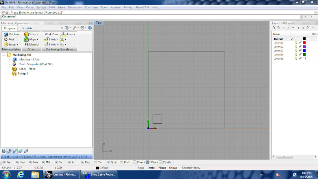
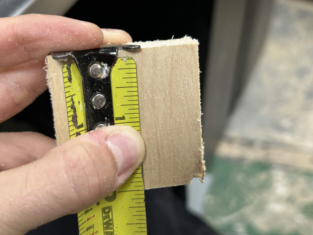
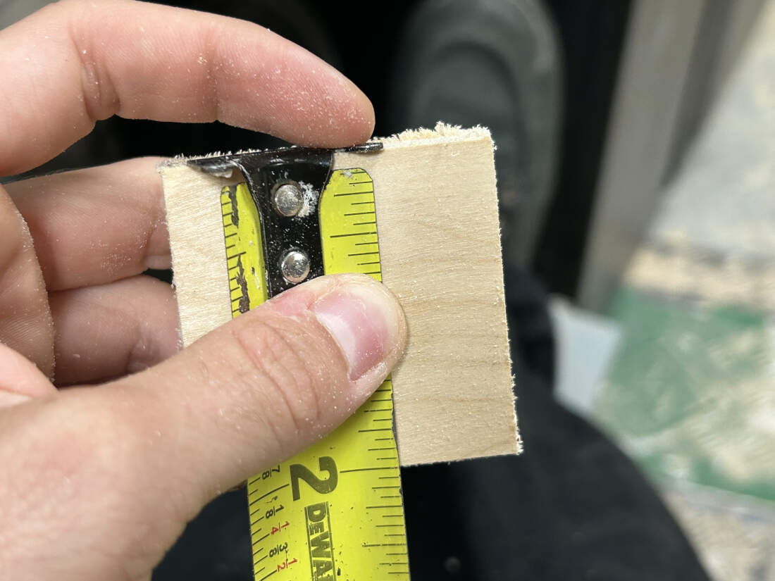
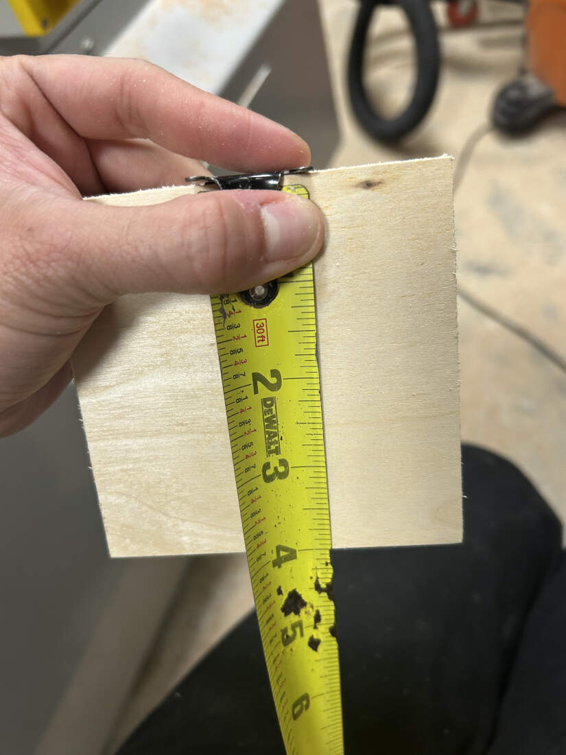
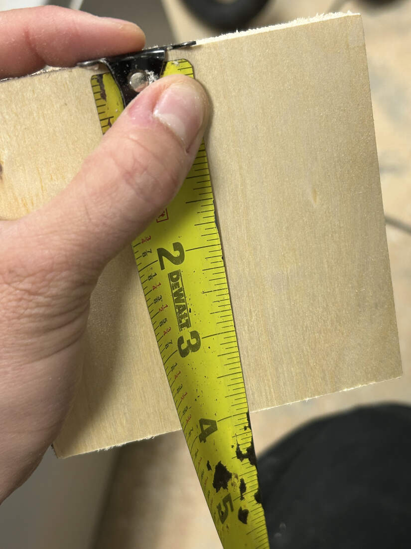
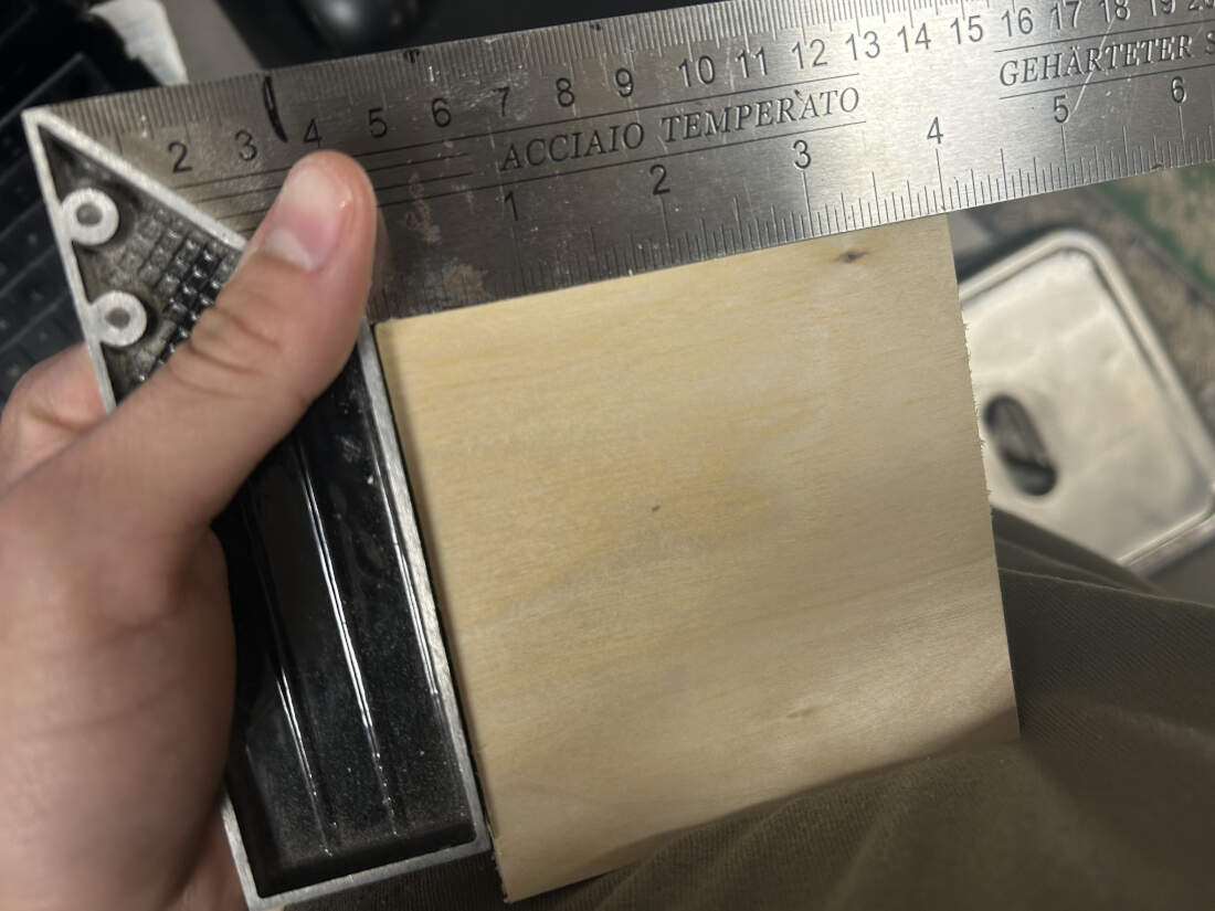
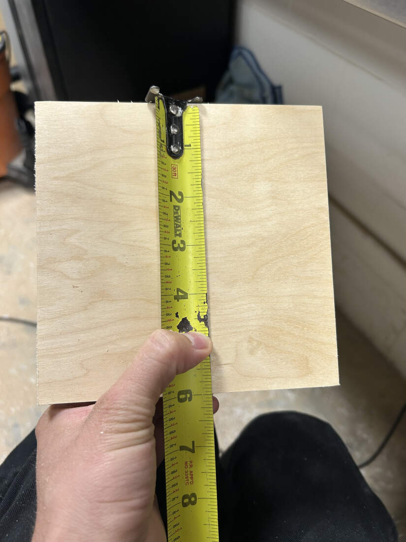
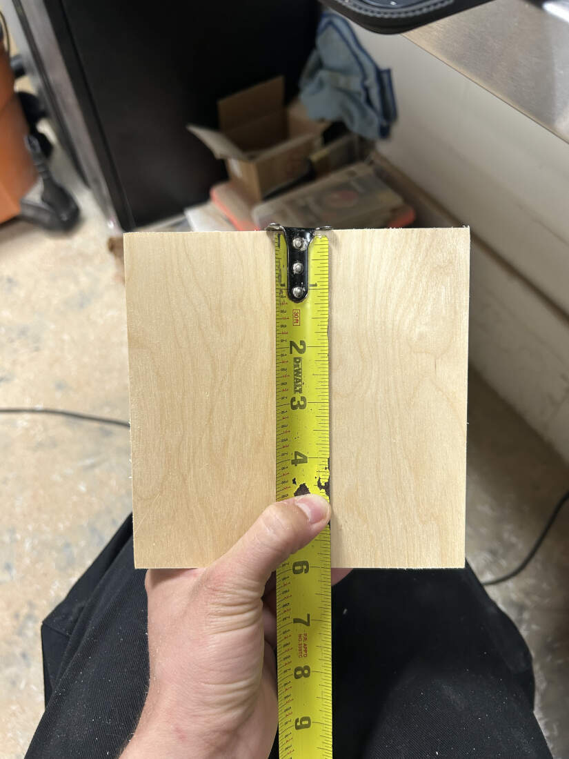
Kerf Measurement - We cut out the square using the CNC and upon measuring it we were able to see that it was cut accurately with 2 inches on both sides. To avoid solely relying on one test we cut out two other squares at 4"x4" and 6"x6". Both were at 4" and 6" on both sides so I guess you could say things were "squared away."
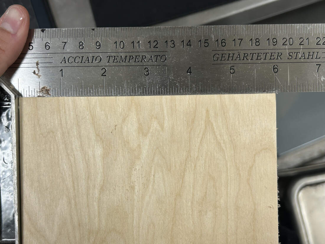
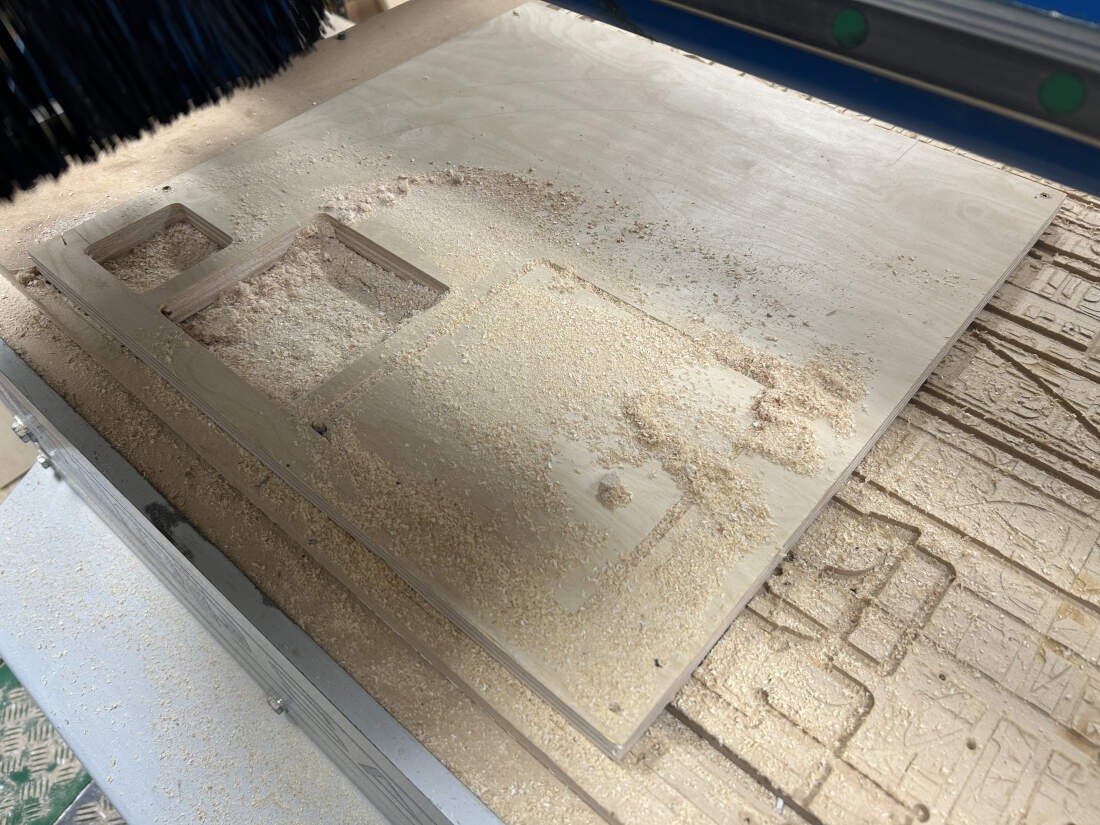
Toolpath Accuracy - Regarding toolpath accuracy, kerf plays a large part in it but so does the programmed toolpath itself. When conducting those tests we used the "Profiling" command which has the option of being set to the center of the line, or inside or outside the line. We choose to cut outside the line and the CNC automatically offsets the toolpath by half the kerf. Additionally, we used a right-angle tool to determine how straight our cuts were and if there was any deviation in its angles. There were none.
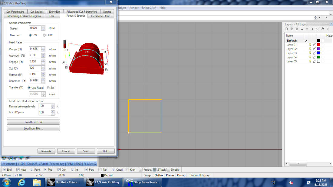
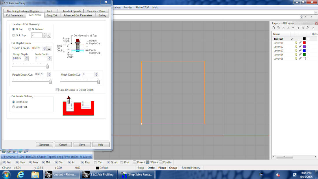
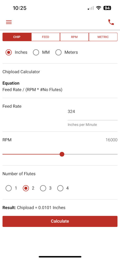
Feeds and Speeds - Our CNC tops out at 18000 RPM but we max it out at 16000 RPM for longevity purposes. The feeds and speeds we use for a 1/4 inch flat endmill are located on Slide 11. Based on the Vortex Tool app, we can push our feedrate to 324 ins/min if we wanted to. Additionally our chipload at the default 120 in/min we leave it at would be 0.00375 and if set to the 324 in/min mentioned earlier it would be 0.010125.
feed rate (inches per minute) / (RPM x number of flutes)
120 (inches per minute) / (16000[RPM] x 2[number of flutes]) = 0.00375
324 (inches per minute) / (16000[RPM] x 2[number of flutes]) = 0.010125
Cut Depth - This is associated to diameter of the bit, but for our typical purposes and for this test we use a 1/4" bit and it can typically cut all the way through a 3/4" sheet of plywood without increasing the amount of passes. If it were a 1/8" bit, we would make sure that the passes were at least two.
Stepover - (diameter/2) This parameter is determined again by the diameter when divided by two. If pocketing or surfacing this is essentially the distance between each successive pass. The larger the bit the less runtime but less smooth a cut is, the smaller the bit the more runtime but smoother the cut is.
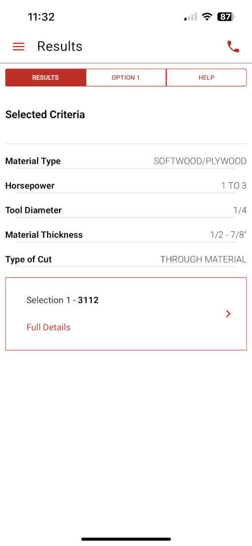
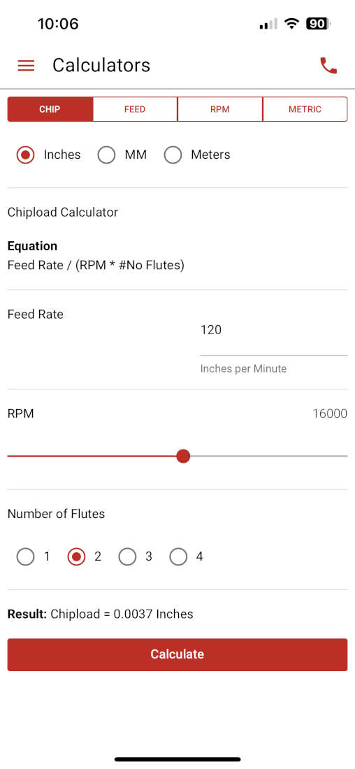
Bit Deflection - This is determined by cutting parameters relating to feeds and speeds and cut depth. In the case of our CNC, we do not cut anywhere near the recommended feedrate of 324 in/min. Since we cut it at 120 in/min. we stay at a safe distance away from any bit deflection issues but are still within a good range that cuts our materials quickly and properly. If we were to cut above 324 in/min. we would risk bending or flexing our bit which leads to inaccurate cuts/ surface imperfections, and if our bit does not break under the pressures being placed upon it we risk it going off center creating runout issues.
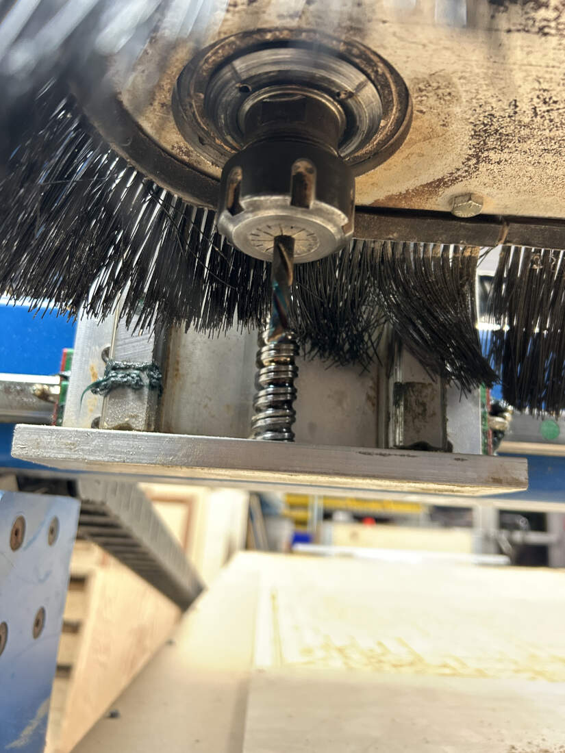
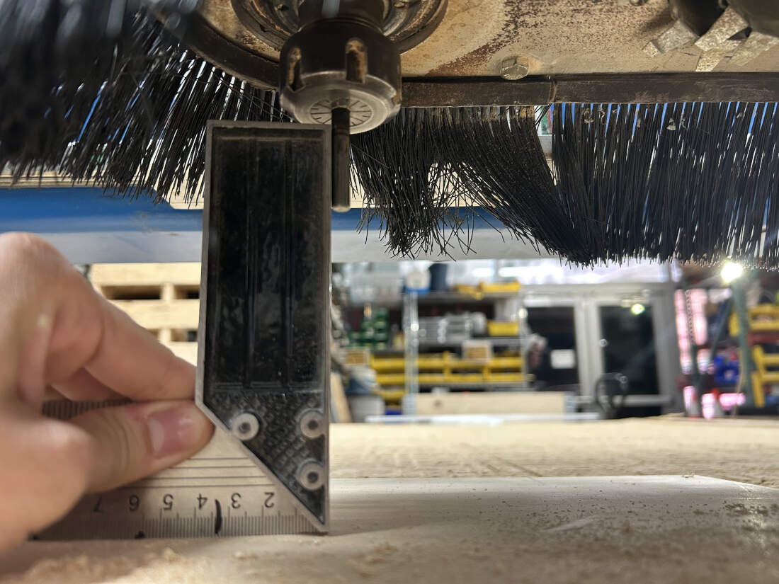
Runout - Runout is a measure of how off center a bit is. To determine if our bit was off center we used a right angle tool and flattened it on top of our work surface and lined up the other end against the endmill. Please keep in mind that we had to flip the endmill around temporarily to see how straight this alignment really was, otherwise the flutes would not have given us a proper idea of how centered it was.