Week 4 : Embedded Programing
Our goals for this week with embedded programing were to browse through the data sheet of a microcontroller of our choice. Then to write a program for it, and simulate its operations with input and output devices and communicate using wokwi. Our group assignment was to demonstrate and compare the toolchains and development workflows for available embedded architectures.
Microcontroller and Simulation
After looking through different types of microcontrollers and taking into consideration what I would like to achieve for my file project, I decided to go with a PR2040.
RP2040 Summary
RP2040 is a low-cost, high-performance microcontroller device with flexible digital interfaces. It has Dual Cortex M0+ processor cores running up to 133MHz. 264kB of embedded SRAM in 6 banks. It contains 30 multifunction GPIO with 6 dedicated IO for SPI Flash (supporting XIP). It’s equipped with dedicated hardware for commonly used peripherals and allows programmable IO for extended peripheral support. Up to 4 channel ADC with internal temperature sensor, 500ksps, 12-bit conversion. This device supports USB 1.1 Host.- For a more detailed breakdown, go to our group assignment for this week
Simulating on Wokwi
- Having never worked with any of this before (in person or simulation) I wanted to run the sample Neil had shown in class and provided code for. In the sample we will be using a button input to light up an LED.- We are using Wokwi, an open-source website that simulates programing and running development boards with inputs and outputs.
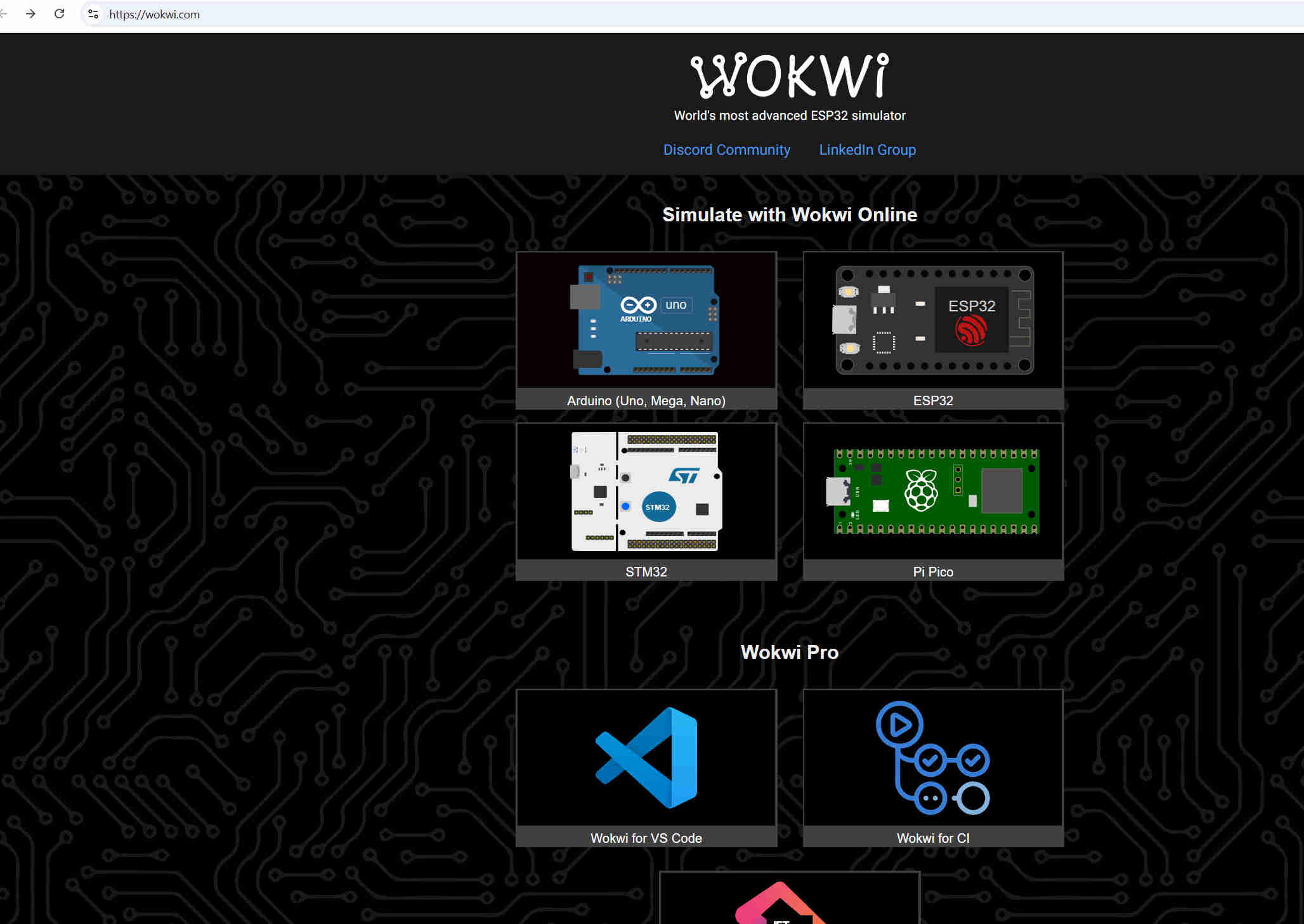
- The sample code was set up for a Pi Pico microcontroller, using micropython as the embedded language.
- Open wokwi on the internet. At the top of the page, you have the option to choose which microcontroller to simulate with. Click into Pi Pico. In the started templates section choose Micropython.
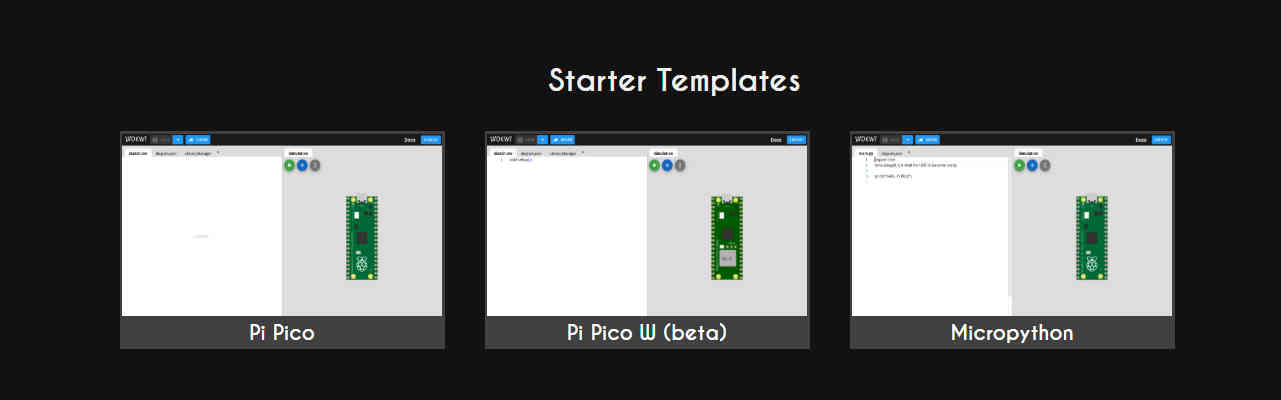
- This will take you to a page that has a section on the left to enter code, a section on the right to “physically” build the structure, and a small section under the build section on the right that is written action happening during the simulation.
- I copied and pasted the provided code. The I started building. You can select different inputs, outputs, ground, etc. by clicking on the plus sign and it will have a dropdown menu of available components. Click on the needed parts and they will show up in your build window.
- Following the pins stated in the code (line 22 and 23) connect your components by clicking the pin and clicking to corresponding part. Once you have everything connected correctly you hit the play button and it will make your build “live”. When I click on the button the light turns on.
Now that I ran the sample, it was time for me to run my own program. My intention for my final project is to have my jewelry/art display stand light up and possibly move activated by motion. Since I got to mess with an LED, I will be programing a motion sensor with a servo motor on a RP2024
- I originally thought I'd use micropython like the test and because others had expressed it was an easier language to comprehend but I ended up using Arduino since we needed to use it in the group assignment and our mentor Peter is more well versed with it to provide great assistance.- Since I am still figuring out code and languages I used chat GPT to help compile code for what I wanted to achieve. When you don’t know where to start and have no clue how to write of even understand code, it’s a helpful learning tool to look at existing/ template code to learn how to read it and use it as directions on how to physically construct it.
#include < Servo.h >

        // Define pins
        const int pirPin = 14;  // PIR sensor input pin
        const int servoPin = 15; // Servo control pin

        Servo myServo;

        void setup() {
            pinMode(pirPin, INPUT);
            myServo.attach(servoPin);
            myServo.write(0); // Start at 0 degrees
            Serial.begin(115200);
        }

        void loop() {
            int motionDetected = digitalRead(pirPin);

            if (motionDetected == HIGH) {
                Serial.println("Motion detected! Moving servo.");
                myServo.write(90); // Move to 90 degrees
                delay(1000);       // Hold position for a second
                myServo.write(0);  // Return to 0 degrees
                delay(1000);       // Avoid immediate re-triggering
            }
        }
To see the full Chat GPT conversation, click on this LINK
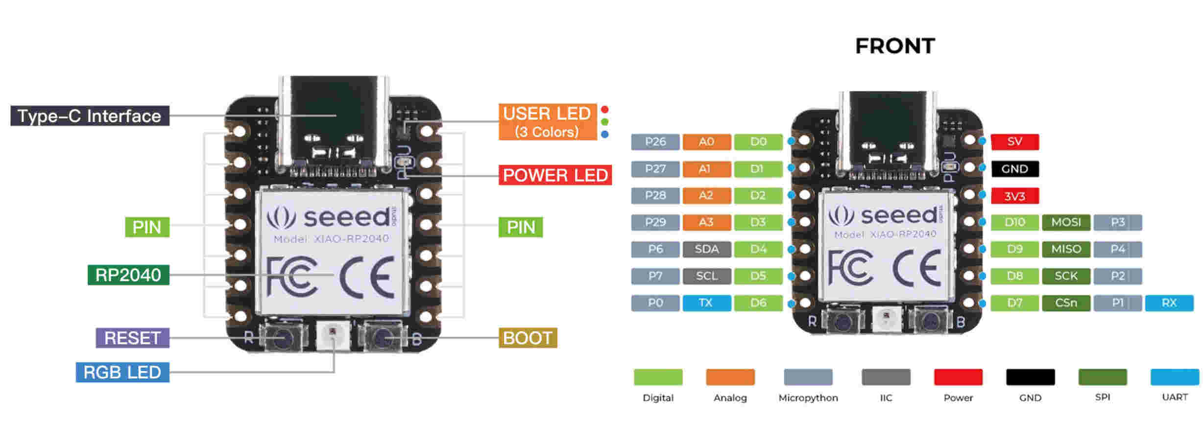
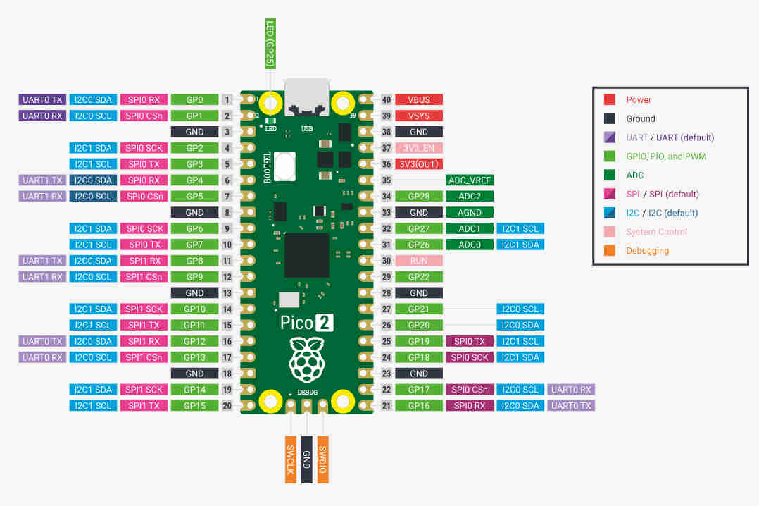
- A key factor in constructing everything correctly is having the pin layout for the microcontroller being used. I my scenario of using the XAIO RP2040, while the simulator has this as an option to simulate, the site does not use the actual chip as the model. It uses the Pi Pico. For simulating on wokwi, use the pi pico pin layout to match connections up accordingly.
- With code help from chat gpt and assistance from Peter going over some of the key things to know on how to read/write code and key components of the inputs and outputs, I was able to get the servo motor to move with motion detection.
>
Group Assignment
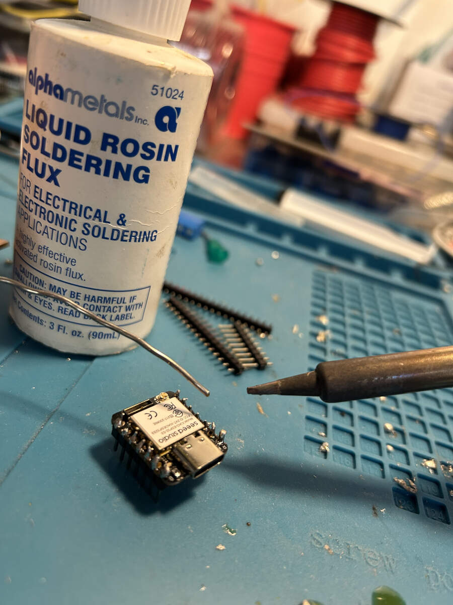
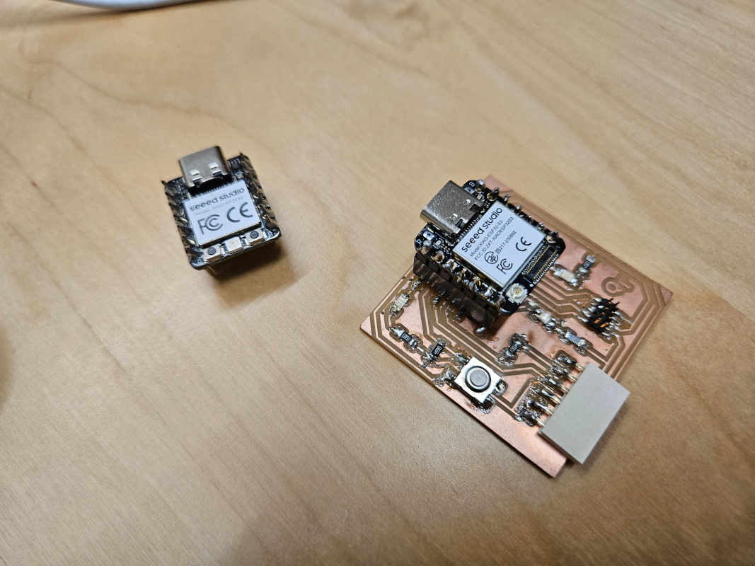
We explored two different boards as a group using a Quentorres board as a basis. This Quentorres was soldered in a manner that allowed us to swap microcontrollers in and out. We made use of an RP2040 and a XIAO ESP32-S3. The RP2040 was already soldered and inserted into the board. The S3 needed to be soldered to compare both. Details about both will be written below.
To understand what we were doing we hopped on the Quentorres GitLab page. We went through a good portion of the guide before we were able to stop using it and find our own grounding.
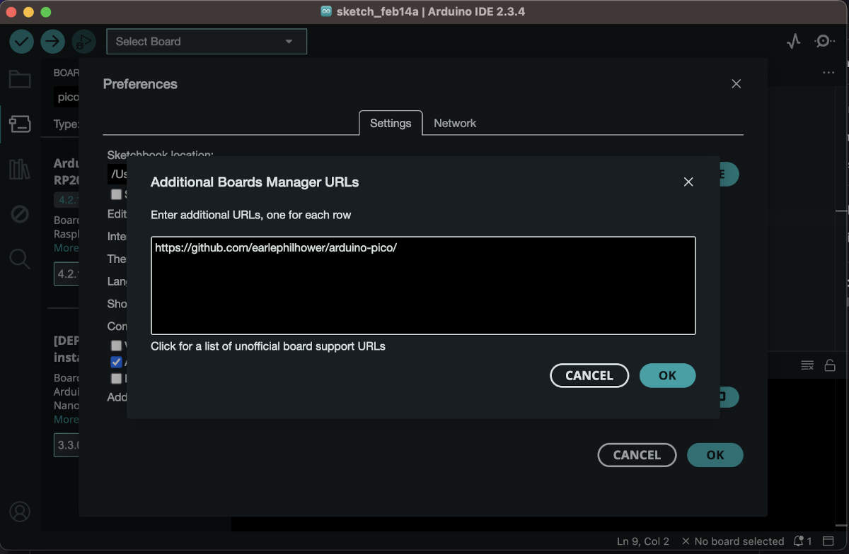
First thing needed is to install Arduino. You need to add the URL of the additional boards. To do so, go this URL first, https://github.com/earlephilhower/arduino-pico/, for all the RP2040 and RP2350 boards, then go to “File” then “Preferences” and add this URL (the image posted below has the wrong link, this one is the correct one) - https://github.com/earlephilhower/arduino-pico/releases/download/global/package_rp2040_index.json
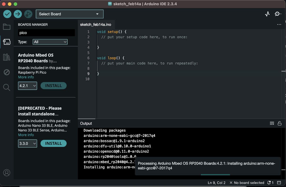
-To download the Pico or the ESP32-S3 board, go to “Tools” then “Board” and “Board manager”.
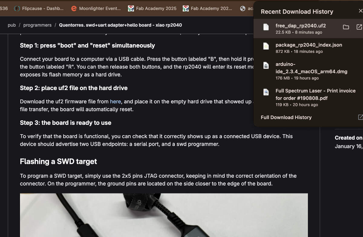
-Before being able to program your board, you will need to boot and reset your board.
- Connect your board to a computer using a USB cable. Press and hold the button labeled "B" while pressing the button labeled "R". Keep holding them until your computer acknowledges the board is connected (like when your computer recognizes a USB being plugged in). Then you can release the buttons.
- Download and place the uf2 firmware on the board(drive) to reset it. This part of the process didn’t work in one go. Honestly we had to do the button holds and rest multiple times to eventually get it to work. Eventually we realized that even though we were following this part of the guide, it was not needed. We realized that we could wipe the board clean and then while connected to the computer, we could upload our Arduino file directly to the board and a uf2 file would be created for it using the test code we took from the Embedded Programming page on FabAcademy.
- Once the reset works and if Arduino is reading that the board is connected then you can verify and upload your code to your board.
 >
>
>
Microcontroller - XIAO ESP32 S3
Use Case/Applications: Motor Control Support, Wireless Communication, Low-Power Efficiency, and Sensor Integration Capabilities
Key Features:
- Wireless Connections
- Wi-Fi
- IEEE 802.11 b/g/n
- SoftAP - can create its own network of devices to connect to.
- Station mode - can connect to an existing network as a client device.
- Bluetooth 5, supports mesh networking
- Processor
- Harvard Architecture based, Dual-core 32-bit Xtensa LX7 CPU. Can go up to 240 MHz.
- Dedicated ULP (Ultra-Low-Power) coprocessors.
- AI acceleration and SIMD processing capabilities.
- Memory/Storage
- 384 KB ROM, 512 KB SRAM, 16 KB RTC SRAM.
- Supports Quad SPI, Octal SPI external flash & RAM.
- Inputs/Outputs/Peripherals
- 45x programmable GPIOs
- 4x SPI
- 3x UART
- 2x I2C
- 2x I2S
- LED PWM (up to 8 channels)
- Motor Control PWM (MCPWM)
- Remote Control (RMT)
- SDIO Host Controller with two controls
- USB OTG
- JTAG
- Power Efficiency & Low-Power Modes
- Multiple power modes: Active, Modem-sleep, Light-sleep, Deep-sleep.
- ULP coprocessor operates under Deep-sleep mode for energy-efficient applications.
- Security
- Secure Boot
- Flash encryption
- Digital signatures
- Hardware encryption (AES, SHA, RSA, HMAC, RNG)
Toolchains:
- Compiler: GCC-based Xtensa Toolchain
- Build System: CMake + Ninja
- Flashing Tool: esptool.py
- Debugger: OpenOCD with JTAG support
Development Workflows:
Use either Arduino IDE, PlatformIO plug-in through VS Code, or ESP-IDF.
- Install Arduino IDE
- Set up and install XIAO ESP32-S3 board package
- Connect board
- Create New Project
- Install relevant libraries
- Write Setup and Loop areas of code
- Compile/Upload code
- Celebrate if it works, cry if it doesn’t
Microcontroller – RP2040
Use Case/Applications: Motor Control Support, Low-Power Applications, and Sensor Integration Capabilities
Key Features:
- Processor
- Harvard Architecture based, Dual-core 32-bit Arm Cortex-M0+. Up to 133 MHz.
- No Floating-Point Unit (FPU), but supports integer math operations.
- Hardware multiplier and integer divider.
- Deterministic real-time performance.
- Memory/Storage
- 264 KB SRAM
- Supports XIP (Execute In Place), 2 MB external QSPI Flash (supports up to 16 MB).
- Inputs/Outputs/Peripherals
- 30x programmable GPIOs
- 2x SPI
- 2x UART
- 2x I2C
- 16x PWM
- 3x 12-bit ADC
- Programmable I/O (PIO) system
- USB 1.1
- SWD (Serial Wire Debug)
- Power Efficiency & Low-Power Modes
- Multiple power modes: Active, Sleep, Dormant.
- Dynamic clock scaling.
- Security
- No built-in secure boot.
- Can implement firmware encryption manually using external security layers.
Toolchains:
- Compiler: GCC-based Arm Toolchain
- Build System: CMake + Make
- Flashing Tool: OpenOCD & USB Mass Storage Drag-and-Drop
- Debugger: OpenOCD with SWD support
Development Workflows:
Use Arduino IDE, PlatformIO, Thonny (MicroPython), or Raspberry Pi Pico SDK.