Week 3 : Computer-Controlled Cutting
We got to mess with machines I am very familiar with and love, the vinylcutter and lasercutter. Our tasks this week are to cut anything on the vinylcutter and design a parametric construction kit that can be assembled in multiple ways and cut it with the lasercutter. Along with these tasks, we also have our first group tasks which are to go over lab safety training, characterize our lasercutter’s focus, speed, power, rate, kerf, joint clearance and types. Even with years of experience with these machines, learning and working with a new way of designing files has kept me humble.
Vinyl Cutting
I got to take advantage of the vinyl cutting project this week with a client job I needed to get done. The client wanted me to remake a design he had on his old golf cart for his new golf cart.
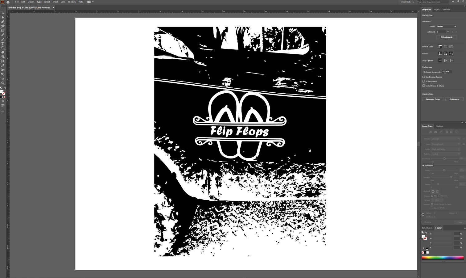
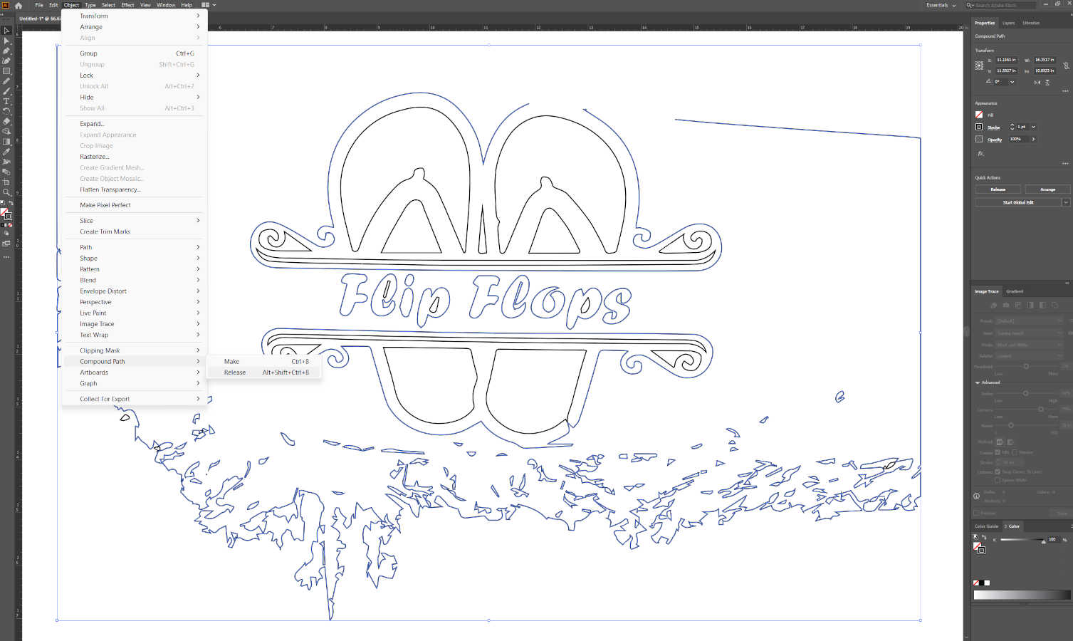
- I worked with a photo of the old design on the cart and converted it into a vector file by “image tracing” it and deleting the access image. To be able to delete the extra unnecessary parts of the file you have to go to “object” then “compound path” and “release.” This disconnects all the individual vector shapes so you can work with and edit individual vector lines and anchor points.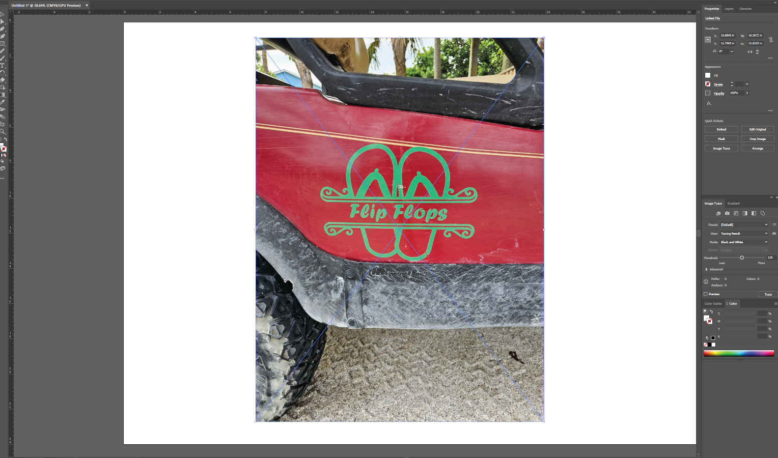
- Once I redrew and fixed any parts that were missed in the conversion process, I “compound path” “made” the remaining file to tell illustrator which lines correspond together so I can fill the files accordingly.
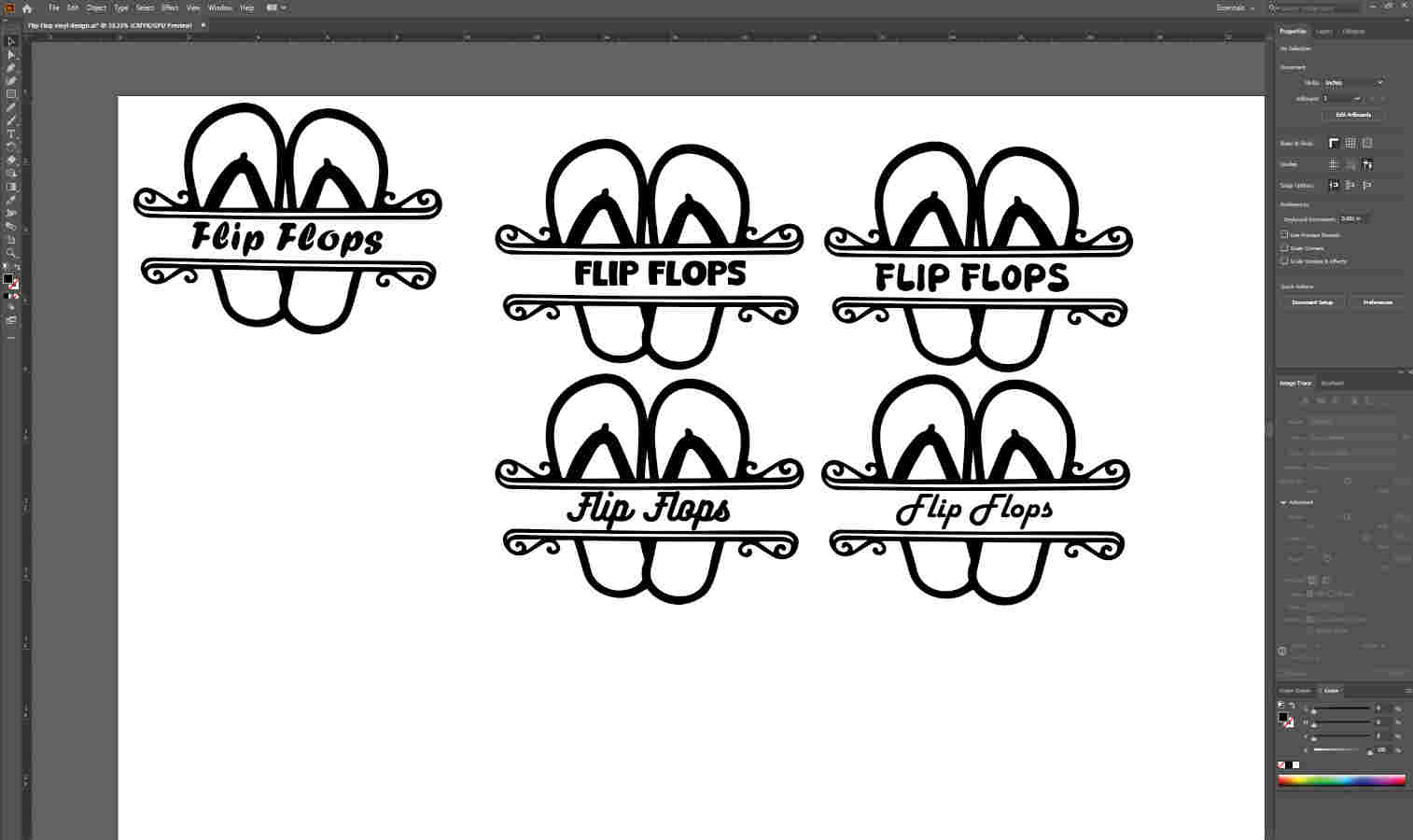
- They wanted the flip flop design to stay the same with different font. I gave them a few different fonts to choose from and from there we go to the vinyl cutter.
The Machine
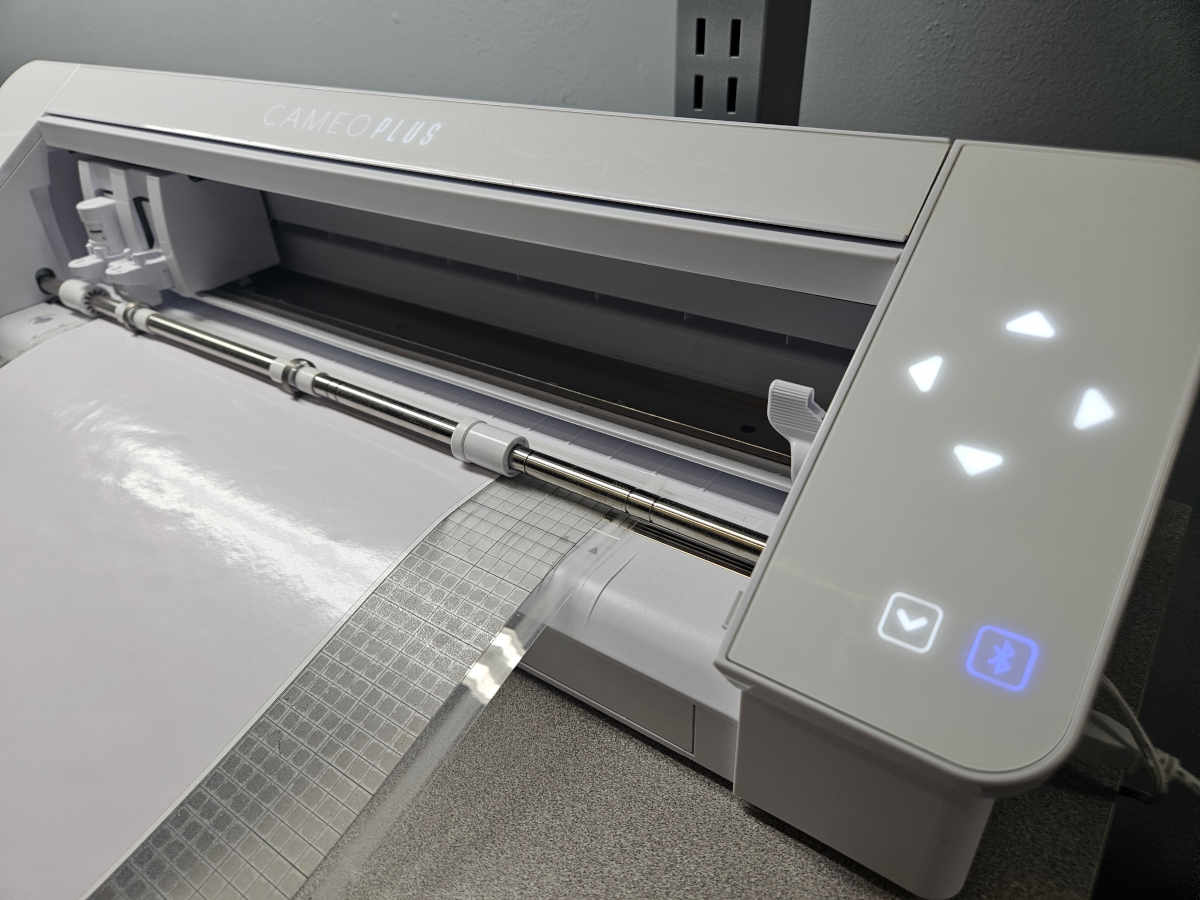
- At AMRoC Fab Lab we have a couple Silhouette Cameo machines. The Silhouette’s use there own software that you can download for free on the SilhouetteAmerica website.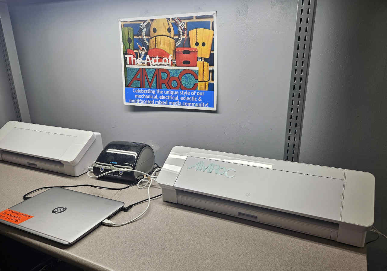
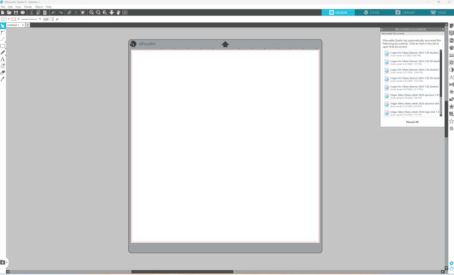
- Once you download the SihouetteStudio software and open the program, it will open with your cutting surface and menu bars with options to choose which machine you are working with and which mat size/cutting size you are using.
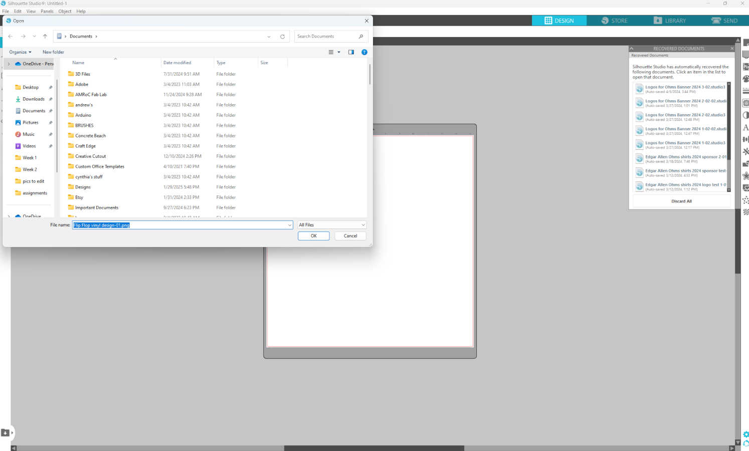
- This software accepts png. Files, so from illustrator I exported the file as a png. In the silhouette software, you go to “file” then “open” and click on you corresponding file. It will open you file in the cutting mat area.
- You can easily check/ and resize your file just by clicking on it and using the perimeter points to scale it. If you’d like to rotate your file, you can click and hold the round green circle that also appears in the perimeter when your file is clicked on.
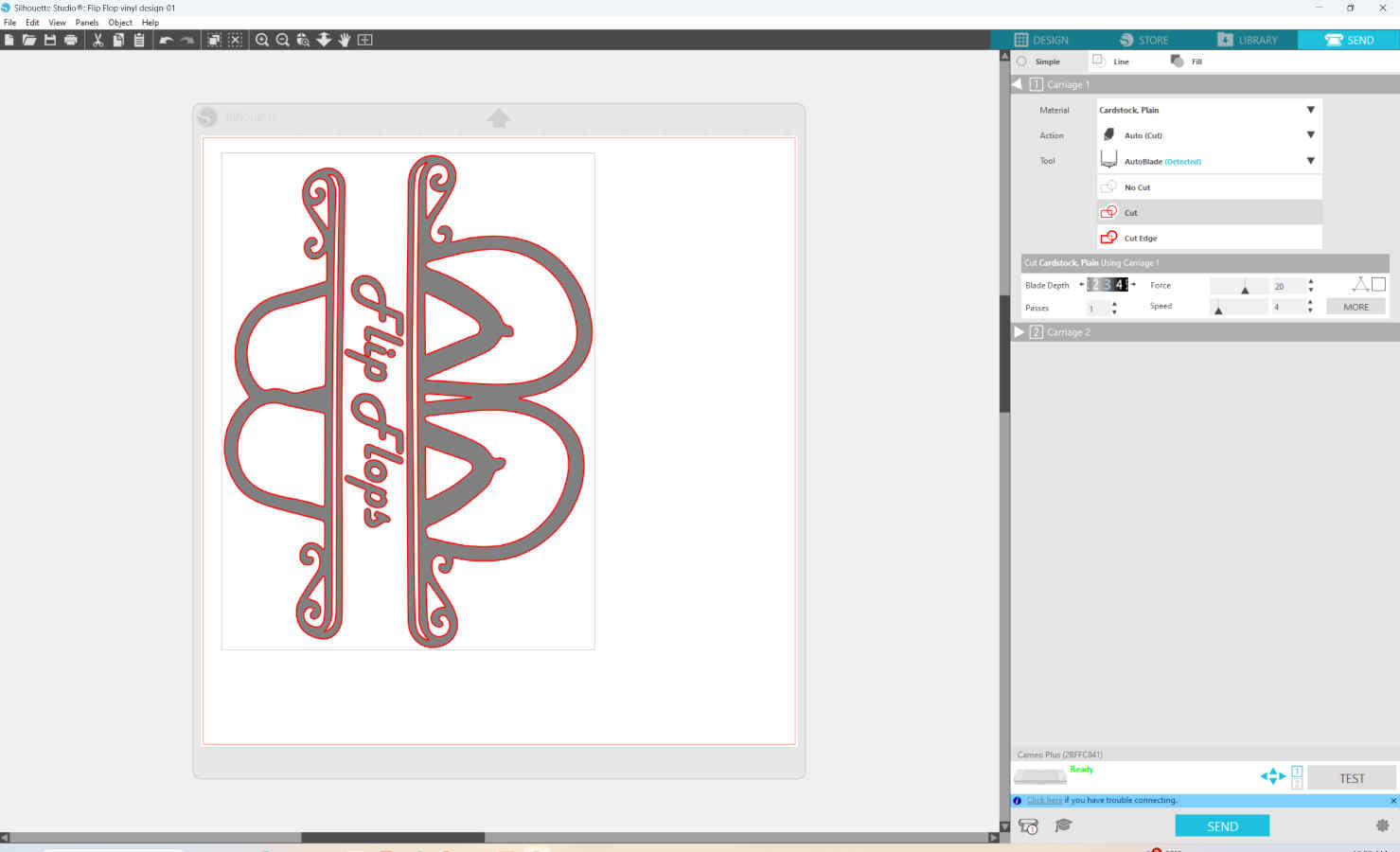
- All of the setting up of the file happens in the “design” tab. When you are ready to cut you file you need to click on the “send” tab in the top right had corner.
- Silhouette has easy to use auto setting with a variety of different materials to choose from. In the materials section, hit the dropdown menu and choose the material you’ll be using. I will be cutting glossy white vinyl.
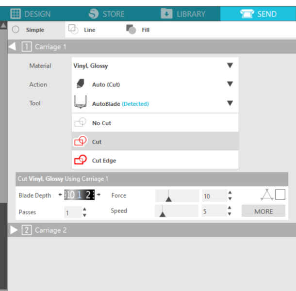
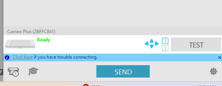
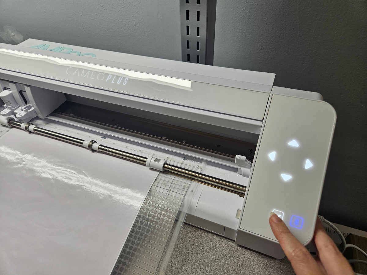
- When you click a certain material, the software automatically updates the blade depth, passes, force and speed of cut for you. This machine in particular, the Cameo Plus, can be connected through Bluetooth or cable, so make sure you are connected accordingly.
- Once you load the mat with your material on it into the machine, the software will say it’s ready to send to the machine. Click the send button and watch the blade magic happen.
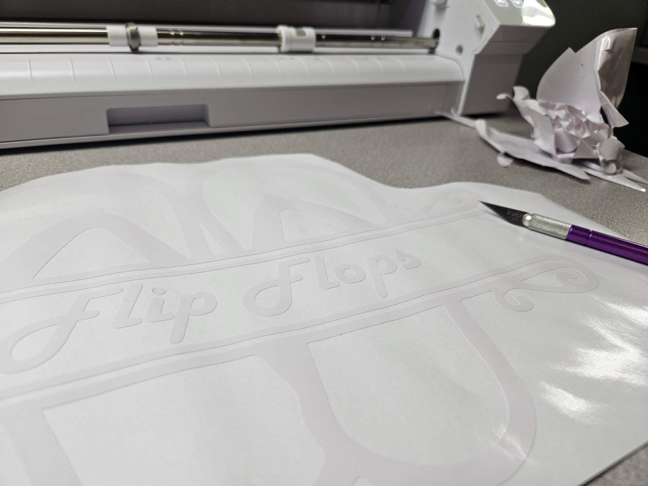
- When the machine finishes cutting, you need to eject the mat from the machine. Remove the vinyl from the mat and start your therapy session by weeding your vinyl.
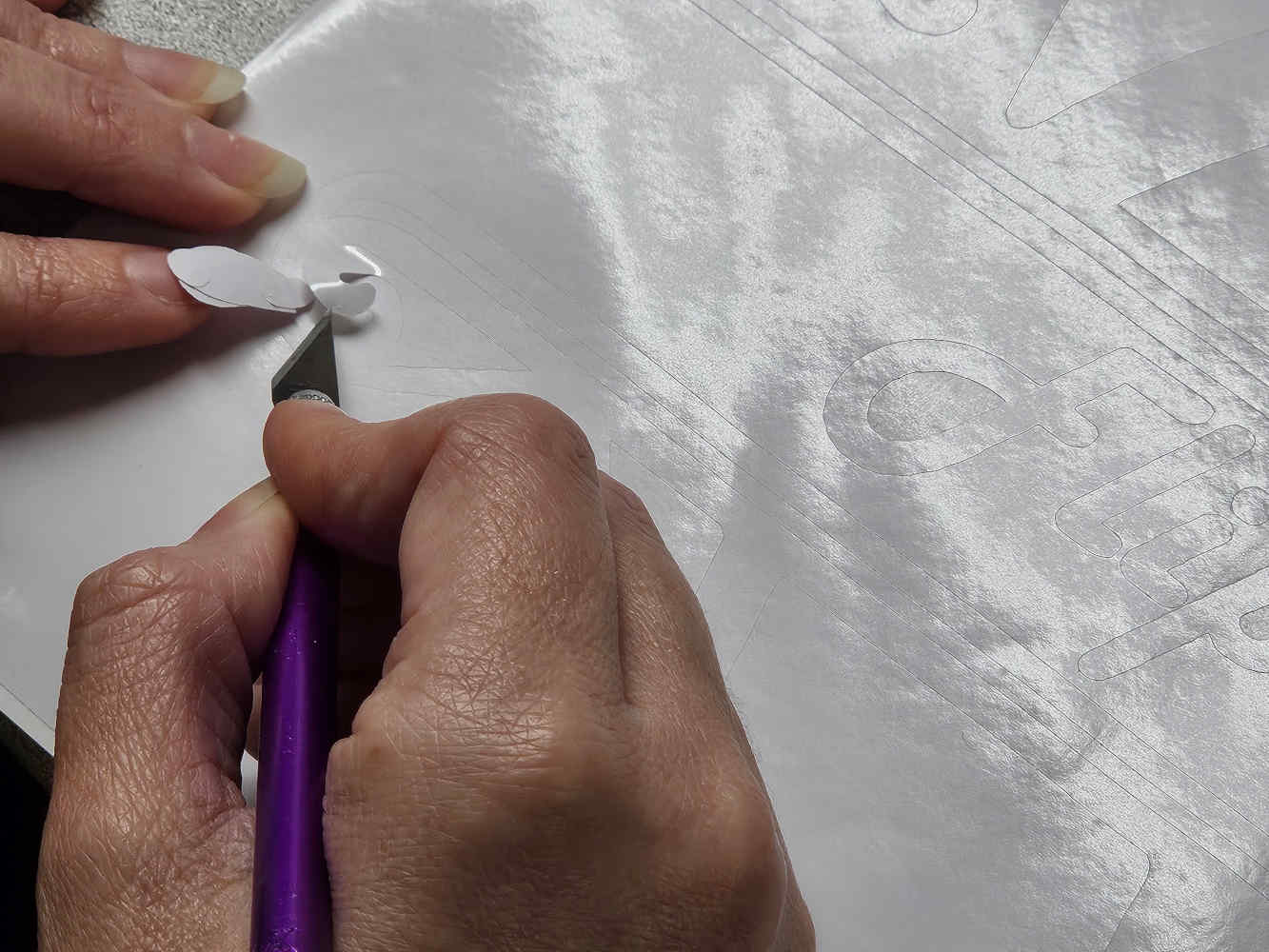
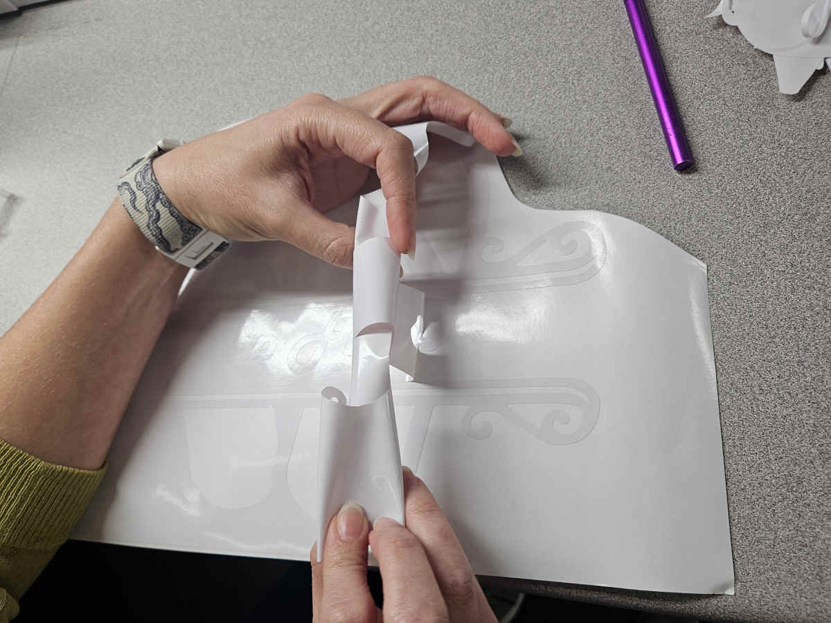
- Weeding is removing the negative pieces of vinyl (the parts of the vinyl that do not make up the design). I thoroughly enjoy this part. I prefer using an exacto knife to pluck out the pieces. If you are removing a large piece of vinyl, it is best to cut it into smaller sections or to roll it into itself so that you don’t accidentally get pieces you want to keep stuck to it.
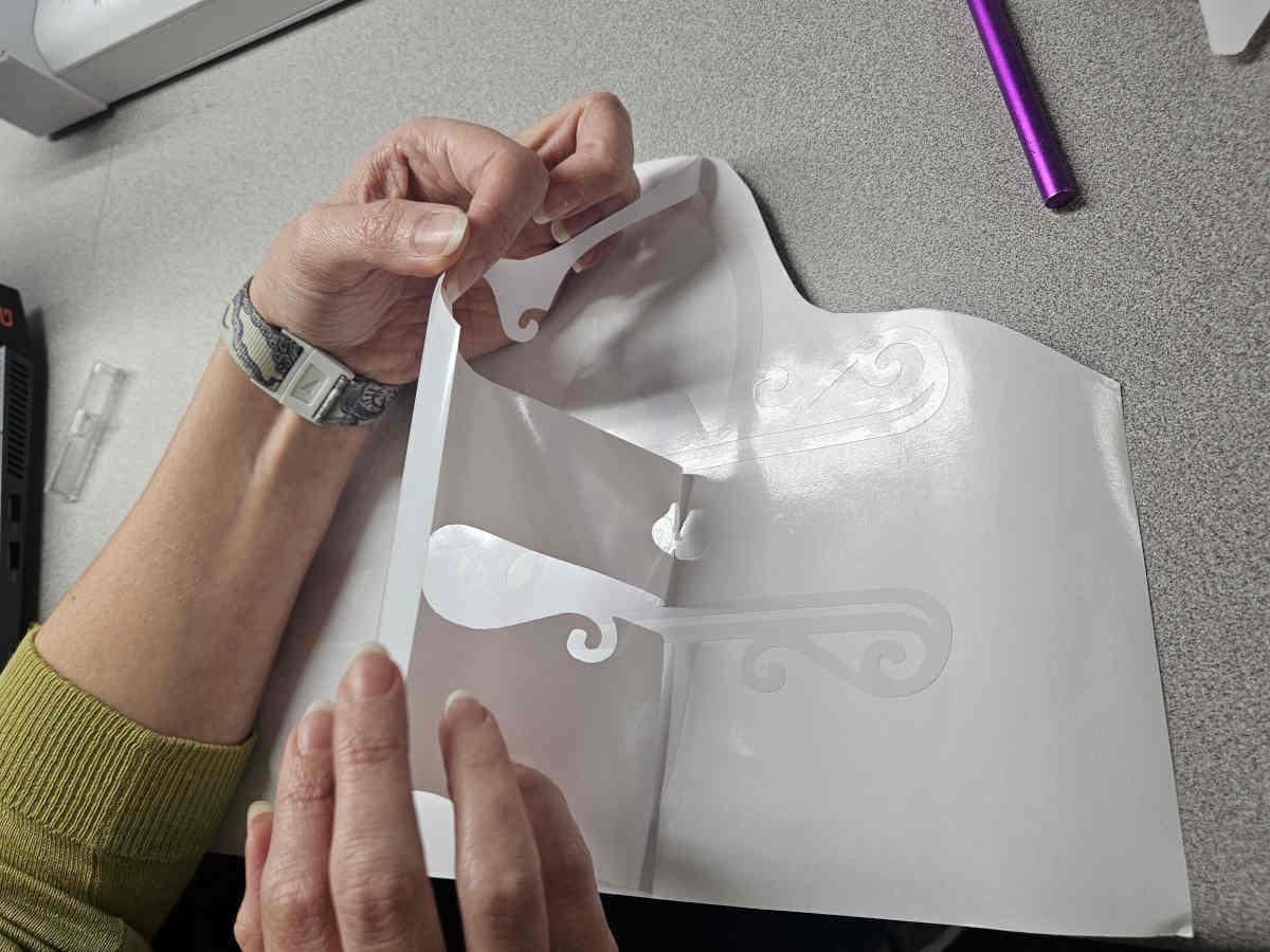
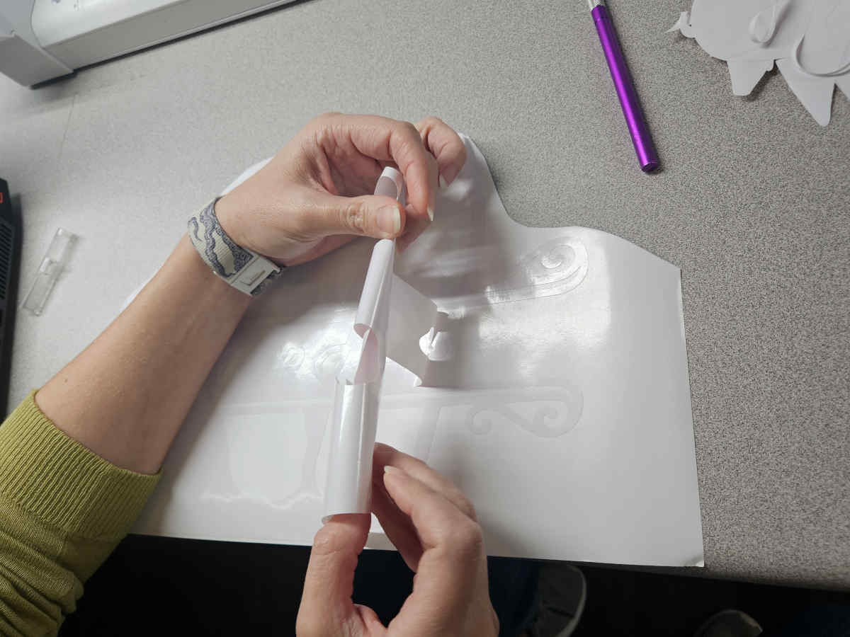
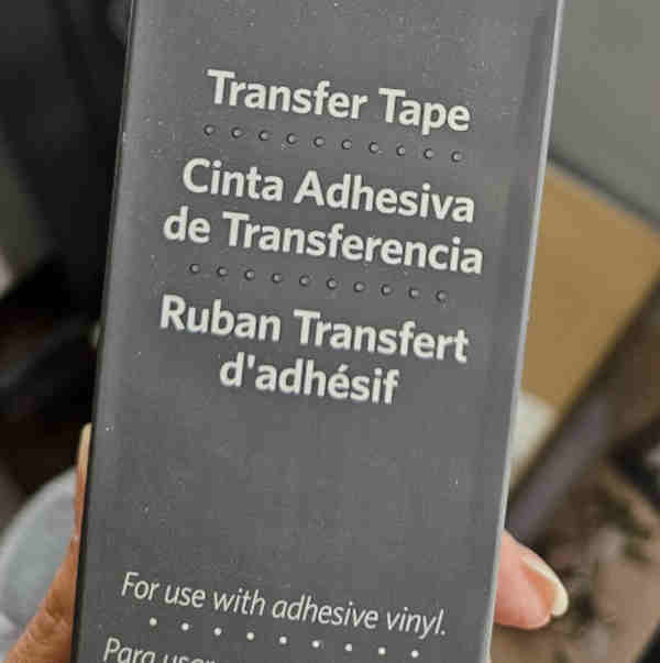
- Complete weeding and apply transfer paper to the remaining vinyl to make it easy to apply to its permanent home. Make sure you apply it smoothly with a squeegee to avoid bubbles and an uneven application.
Laser Cut Parametric Construction Kit
We are continuing to learn/practice using Fusion 360 this week for the parametric constriction kit. I decided to make four pieces. An octagon, a curve, and two angle pieces (90 and 135 degrees)
- In Fusion, I started by changing my units to inches because I’m a silly American and I realized last week I was doing extra work by either converting measurements or needing to double check my units all the time.
- After units were set, I immediately made my user parameters.
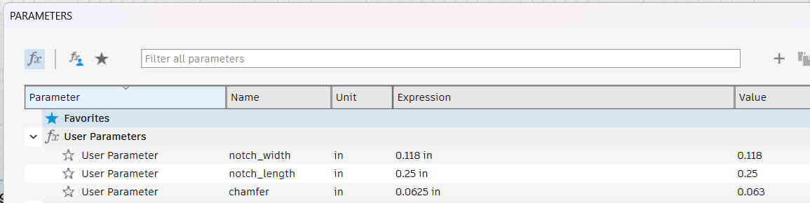
- I started with the polygon tool to make my octagon. I then added in my notch as a rectangle using set parameters for its size. I was please to find out that Fusion has a chamfer tool because I wasn’t necessarily looking forward to make them from scratch.
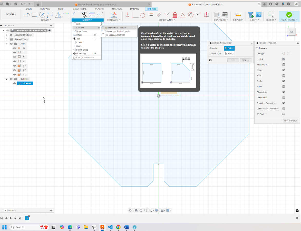
- Once trimming the first notch, I used the circle pattern tool to add a notch on each side of the octagon. Trim the new notches and now you’ve got an eight notched octagon.

- I wanted to create a shape that was a little less geometric so I drew out a curve. I copied the curve to give it width and enclosed the edges to make it a solid shape. I built out each notch here since the object isn’t symmetrical. Adding the third notch in the center of the curve was good for experimentation but not the most effective at the angle I made it at. A thing I didn’t consider was being able to add chamfers on the curved edge. The program did not allow me to add them (or I did not figure out how to), so I used fillets instead.
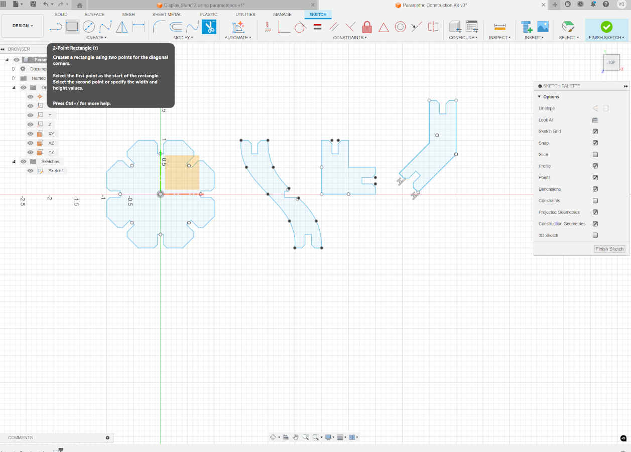
- For both angle pieces, I made a plain rectangle piece with a notch in it and the “copied and moved” the copy. There is an option to rotate the piece while doing so and you can type in the angle you desire.
- Oddly enough, a step that I thought I needed to pay no mind to ended up being a hassle. I saved my Fusion file as a .dxf to be able to open on Illustrator to nest pieces and eventually lasercut them. My Illustrator would not open or read the .dxf file. I went to google, chat gpt, Fusion help, Illustrator help and could not come up with a solution to make my files and softwares compatible. I tried saving different file types, restarted programs, the works. Just to be able to get work done, I downloaded FreeCAD, opened my Fusion file there and then exported it as an .svg and .pdf.
- side note: after going through all the round abouts and finishing the project. I spoke to Augusto and he showed me how to convert my file into a .pdf from Fusion -_____- lol . Once you finish your sketch, click on the HUGE design button. Go to “drawing” and click “from design”. It will open a new tab with a layout page where you can choose what angle you want your 2D file to be viewed at. Then export as a pdf.
- side note to the side note: In my hours of searching the web and AI, not one source mentioned the solution Augusto shared with me.
- Finally, my files opened in Illustrator and I nested the designs to fit the cardboard material I’d be using to cut from, utilizing as much material as possible. We love saving material and not wasting any space!
- At AMRoC we have the same brand of lasercutter but different model than Moonlighter. Regardless of model we use the same software that is web based.
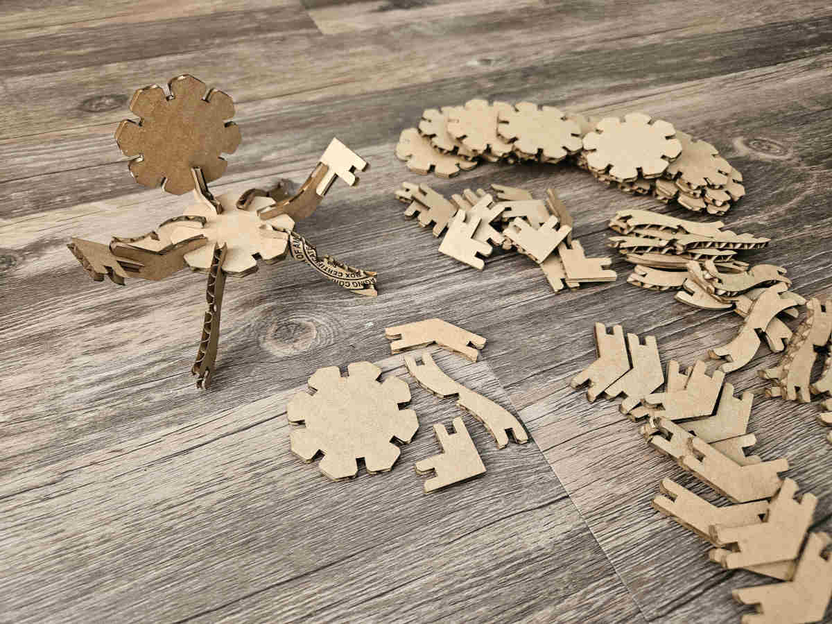
- I ran a test of each piece on 1/16 inch cardboard with the 1/8 inch notches (actually .118 inch notches), to see how they look together and test it on the 1/8 cardboard before running the whole batch.
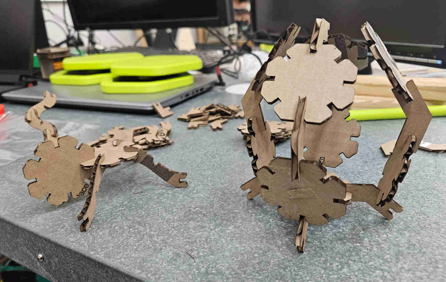
- The test joints fit great first shot. All that was left to do was run a good hand full of pieces on the correct material. The pieces work well and can make all different configurations. I intentionally ran it on cardboard to be resourceful, but after playing with cardboard pieces more than a couple times, they lose their rigidity. For future construction kits, I plan on cutting them in wood to have a longer lifespan.
Group Assignment
This week we were tasked with characterizing our laser cutters. We set out to record the lasers focus, power, speed, and kerf, in addition joint clearance and types for when we cut out our own parametric construction kits.
Safety Training
As former and current employees of Moonlighter FabLab, Victoria and Augusto have both undergone safety training relating to the laser cutters near the beginning of their employment at the lab. Both went through the Laser Cutting Basics class that we offer with either Tom or Daisy, the founders of the space, and both have completed the neccesary certifications related to operating a Full Spectrum Laser cutting system.
Some of the most important rules to keep in mind for operating laser cutters are -
1. Inspecting laser cutters for breakage or damage before each use.
2. Turning on all auxiliary systems, the air compressor, water chiller, and air exhaust before use. The water chiller is necessary to operate the machine and the other two mitigate potential safety hazards.
3. Never leave laser cutters unattended. Doing so risks create a fire hazard.
4. The red emergency stop button cuts off all power in case of emergencies such as fire hazards. If needed a fire blanket and/or CO2 extinguisher is recommended to put out CO2 laser fires as they are the only approved means of doing so without damaging the equipment.
5. Clean after use. Clear the bed from debris, tapes, jigs, and/or guides to prevent fire hazards. Removing the bed may be necessary.
6. Chemical composition of materials are a good thing to keep in mind. Some materials like PVC and vinyl will harm either you or the machine with toxic and/or corrosive fumes.
7. Keep hands away from moving mechanical parts.
Laser Focus
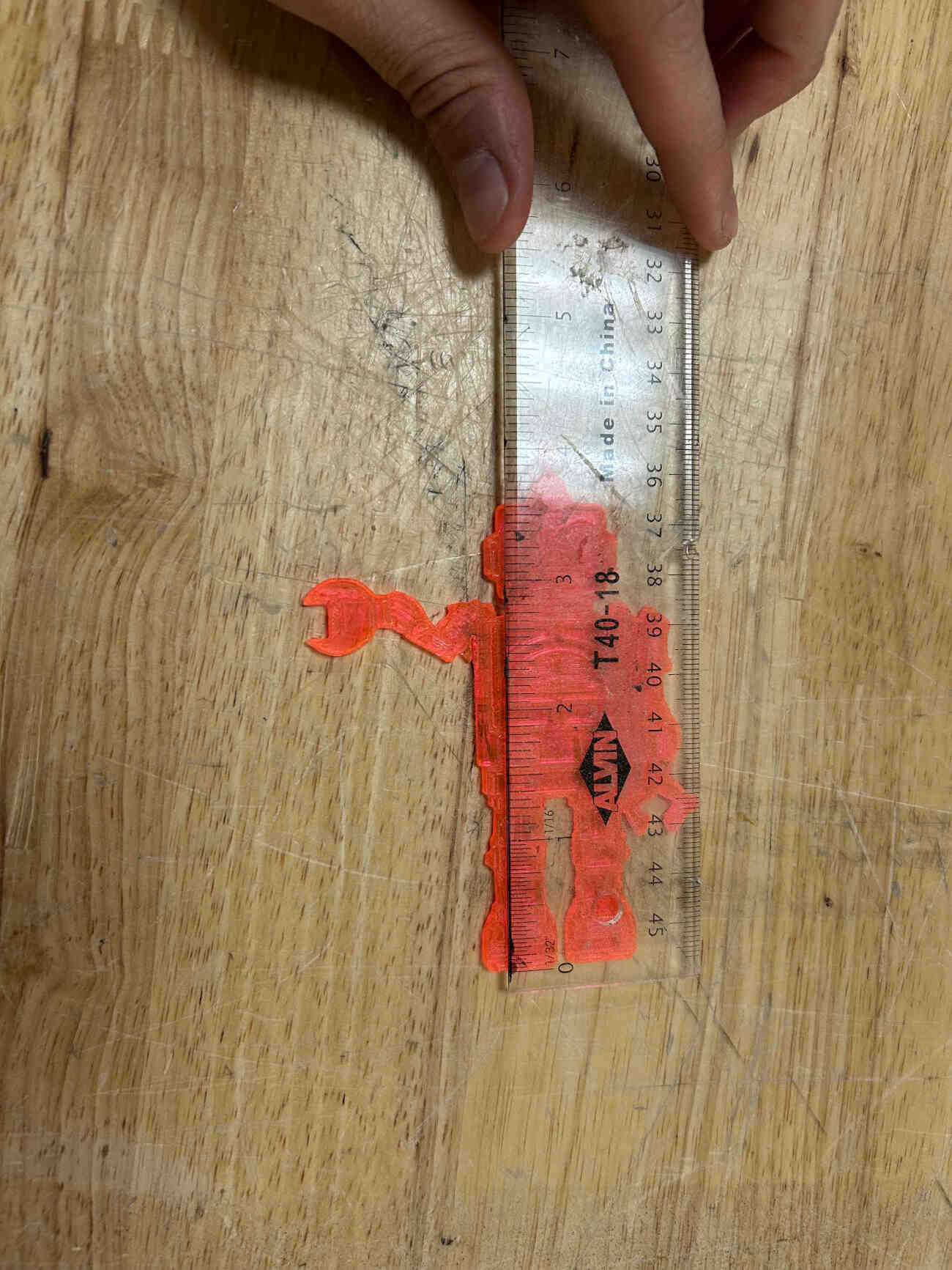
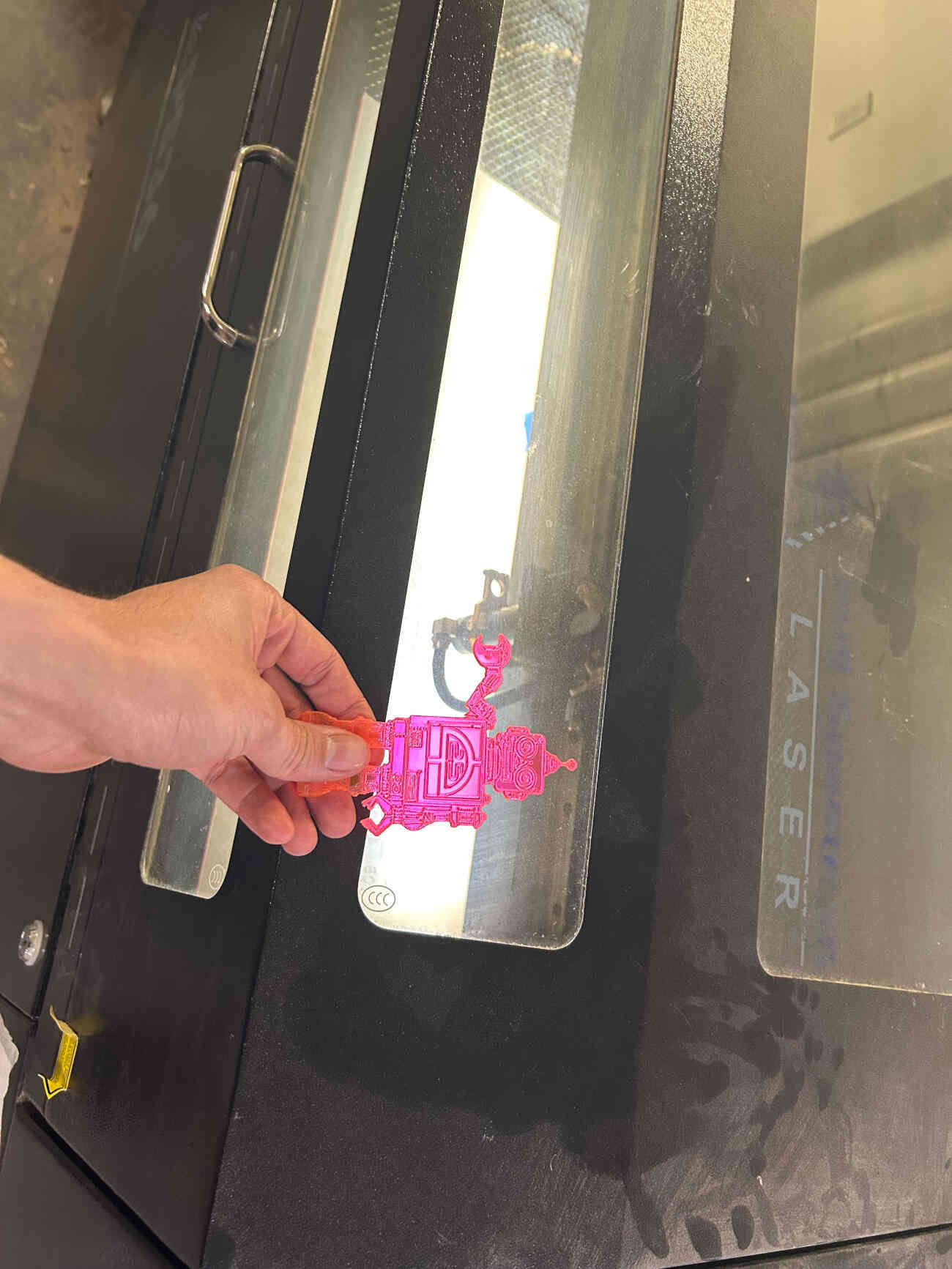
Our laser cutter operates without an auto-focus laser meaning we have to manually measure the distance between the lens and whatever material we cut. With this in mind, we did research on our laser cutter and found out that we are currently operating with a 2.5 lens. The ideal focal distance for a lens of this type is 63.5mm or 2.5 inches. Luckily we already had pre-existing focal ruler templates with our space. We use a robot with a small arm to measure the distance between the midsection of the nozzle, where the lens is located, and the material you are using. To ensure that this ruler was fit for the job we simply measured the distance between its feet and its arm and found that it was 2.5 inches as needed.
Laser Power and Speed
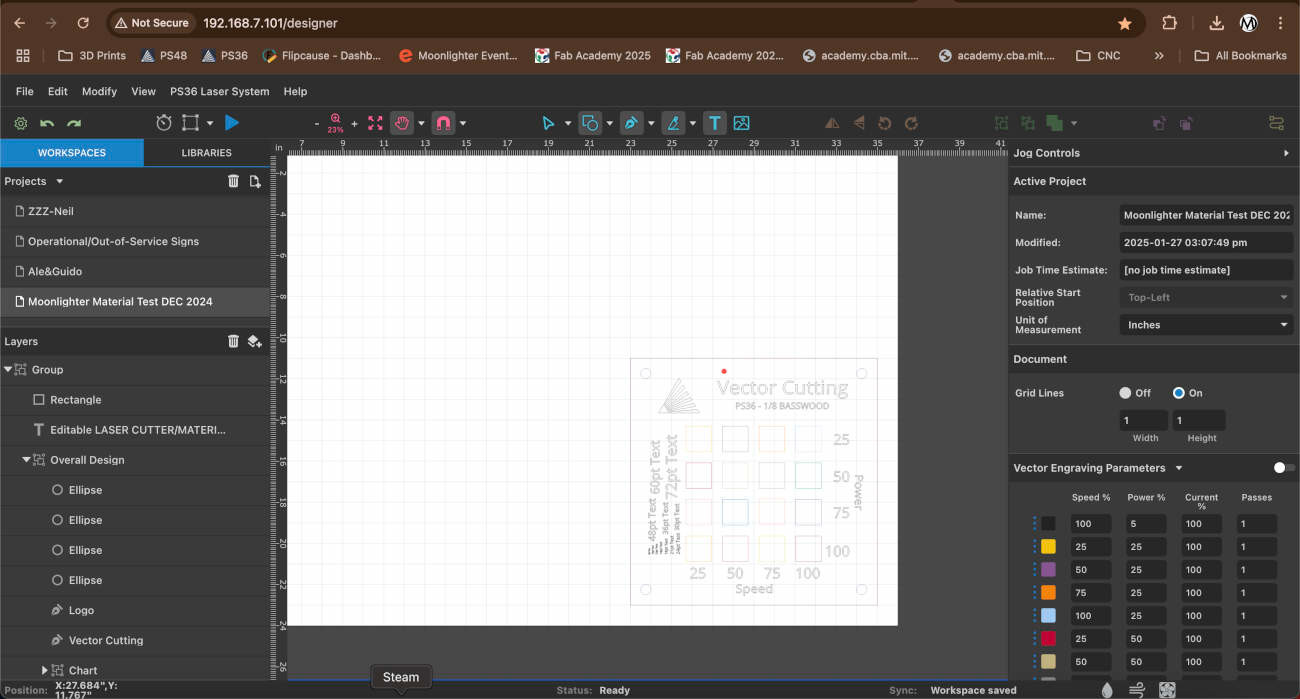
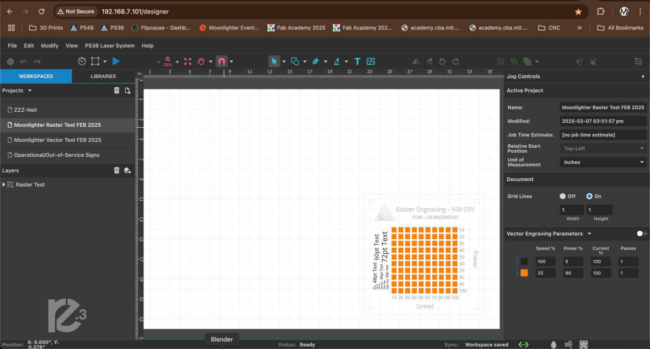
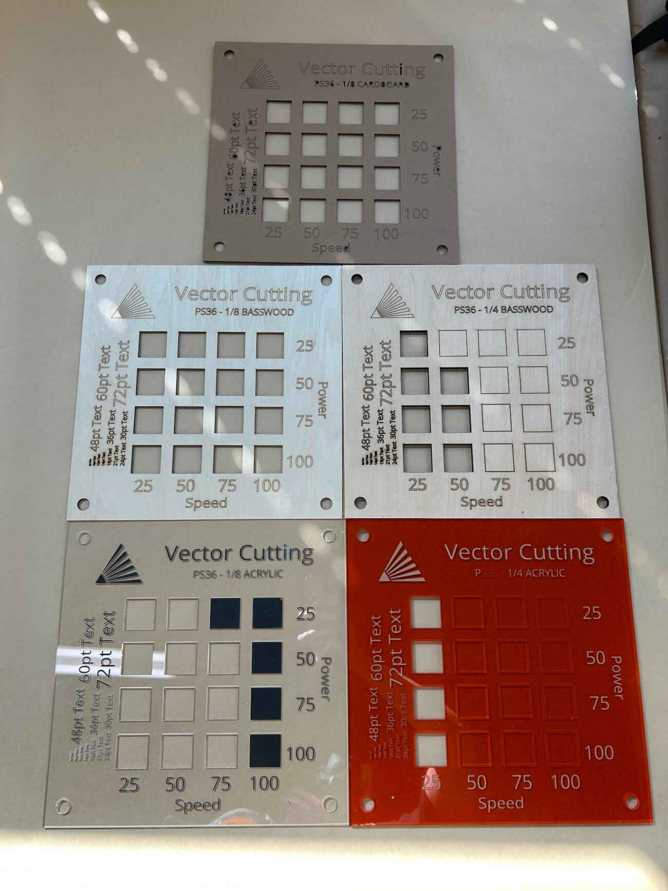
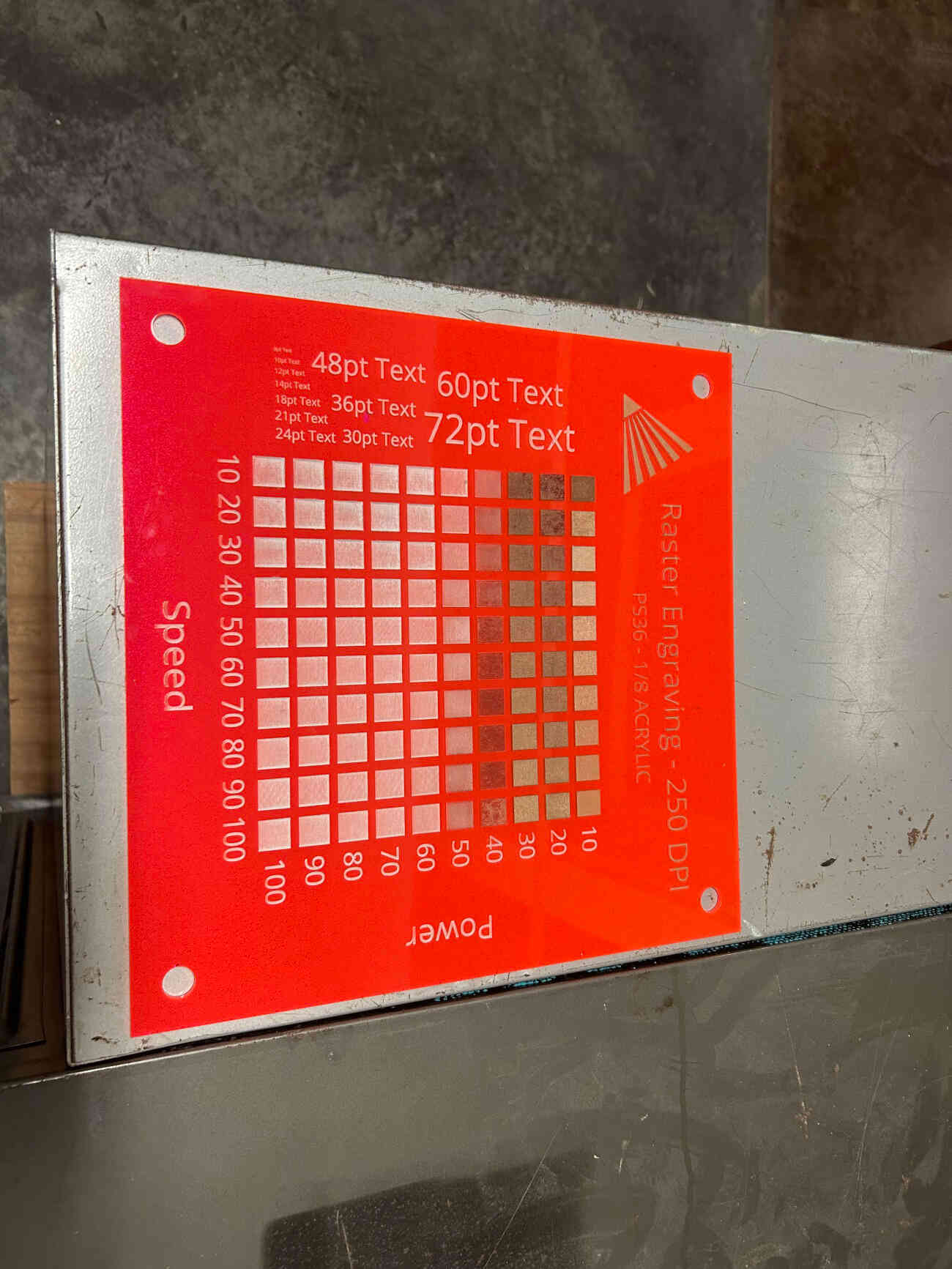
Once our focus was in order, we set about shifting our attention towards power and speed which was rather easy thanks to Full Spectrum Lasers, the manufacturer of our laser cutters, vector and raster tests available on their website. We were not satisfied with the tests as they were especially since they were rather small and easy to lose so we chose to modify them. The modifications to their templates included a resizing, making each 12"x12", the addition of holes in each of the four corners, this is for display so members can see what works, and the addition of fonts on the left side of the template, so anyone can see what font sizes are readable and which aren't.
Laser Kerf
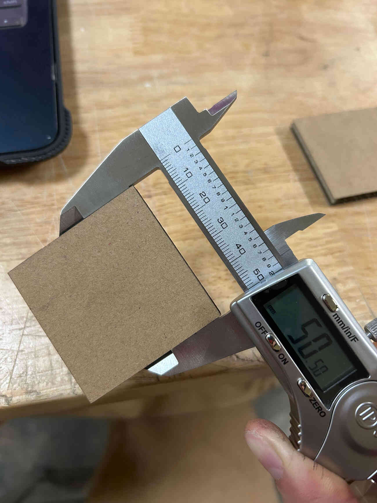
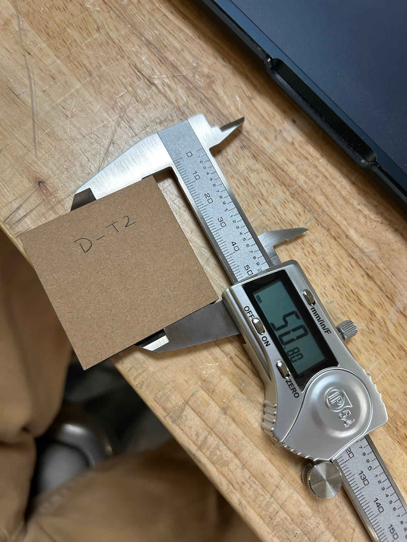
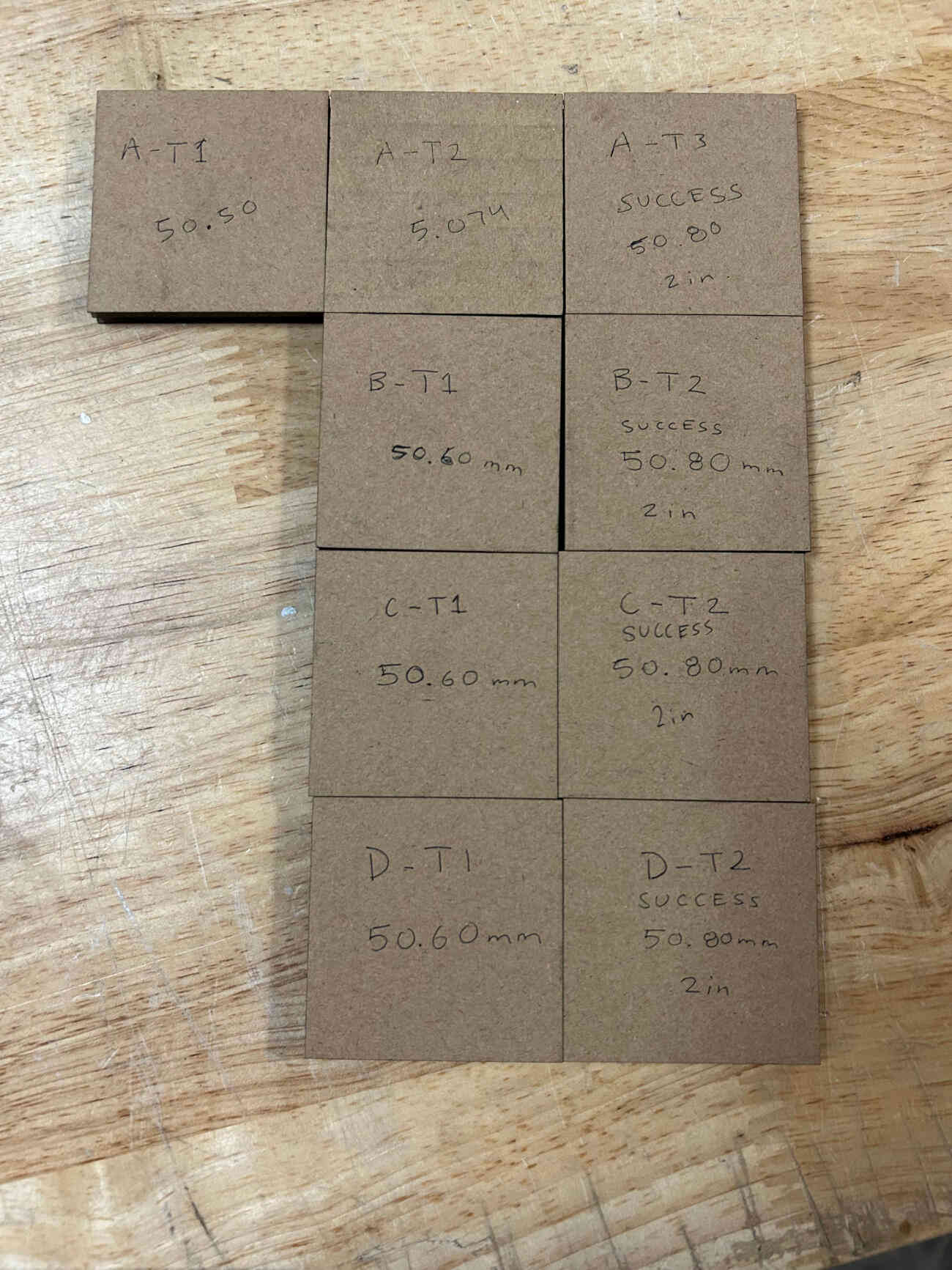
We set out to cut 2 in. (50.8mm) squares in 1/4 cardboard and using a caliper for extra precise measurement we found out that our first cut was off from 50.8mm exact by a bit. We tweaked it further by increasing the size of the square by .14mm and realized we were still short so we increased it by .06mm. This third run allowed us to physically get 50.8mm with our cuts but digitally we had to program the square to be 51mm in both length and width. The odd thing we noted after is that even though we had noticed a 0.20mm difference in the kerf, after measuring our first run again we realized it came up to 50.5mm and our last run was what we needed at 50.8mm. We concluded that our inconsistent power and passes settings may have altered the results so we did three more rounds of testing at 100 speed, 60 power, and 1 pass. Each consecutive set of tests were simpler now that we knew the overall offset of 0.20mm and each test was able to successfully get to 50.8mm physically while keeping the 51mm measurement digitally. In conclusion, the offset we have to take into consideration is 0.10mm for each line cut if we want to get perfect and precise sizes and measurements for any future cuts.
Joint Clearance and Types
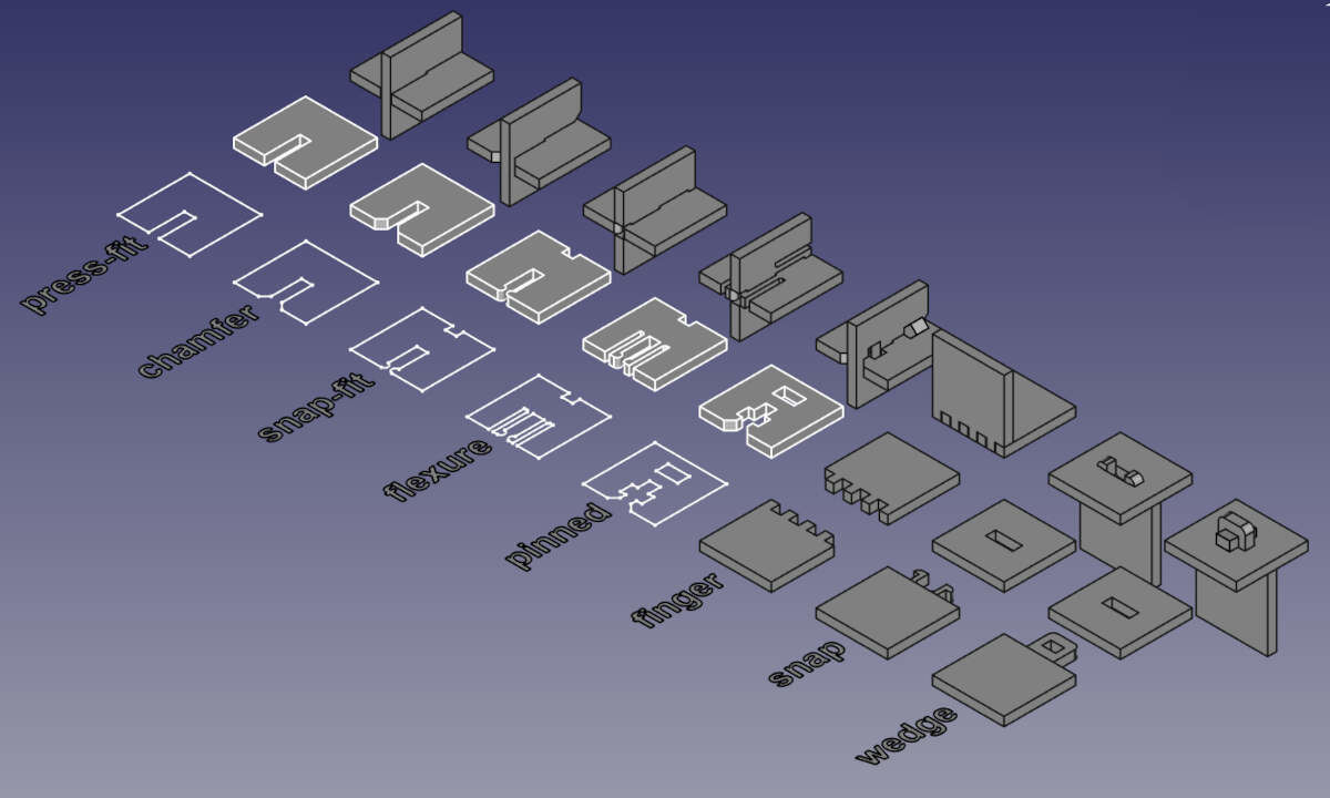
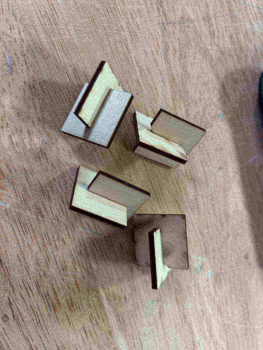
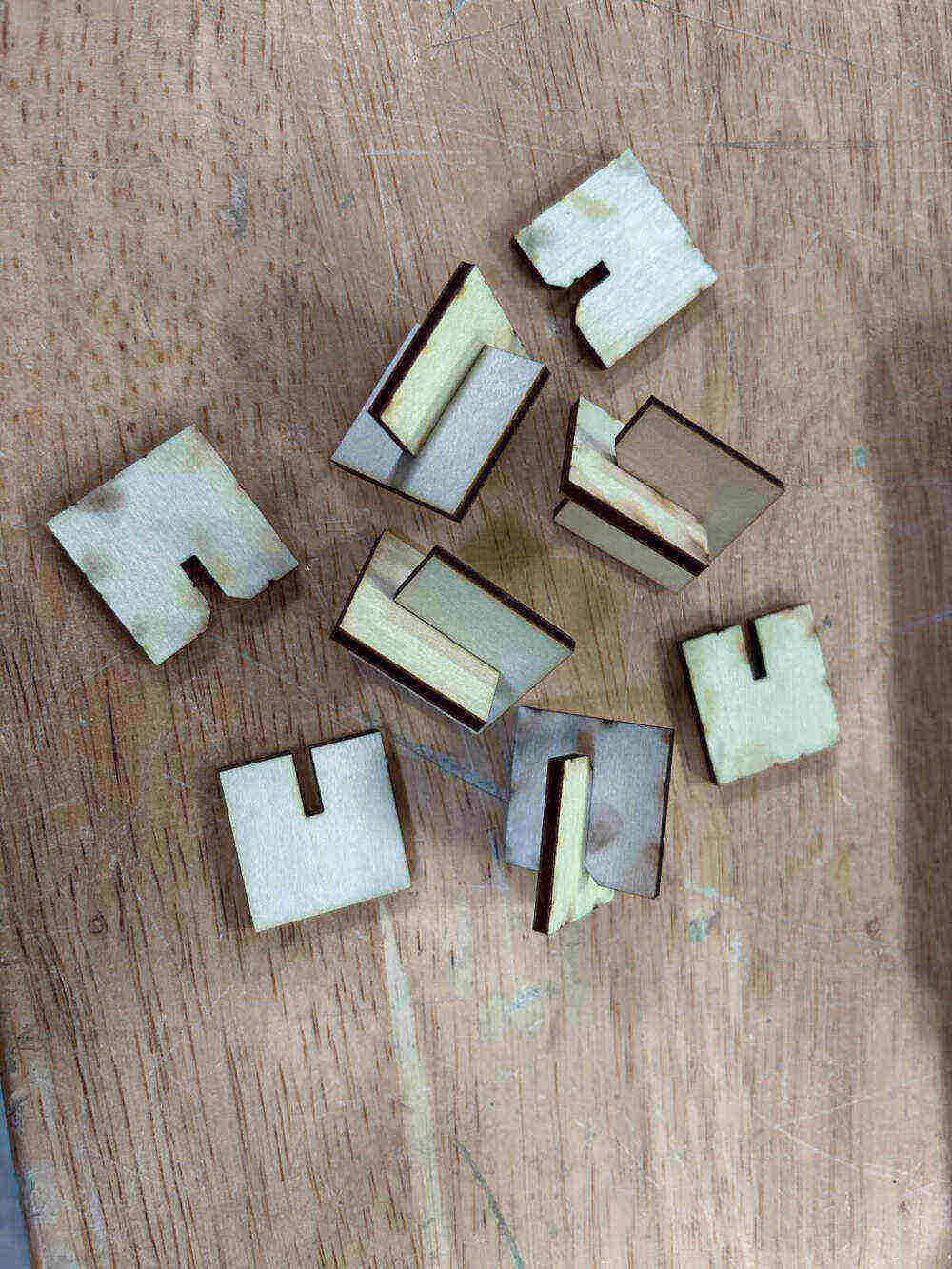
Both of our projects utilize simple joints. We resorted to press-fit and chamfered and that is what we cut and tested. Both worked for what we had but we noted minimal differences between each as they are both essentially press-fit, the only difference being that the chamfers for the chamfered joint serve as a funnel that slides any connections into place. We did take note of the various different types of joints one can cut below.
Press-Fit - The most basic joint. Thin slot on any surface that slides in together.
Chamfered - Just like the press-fit except the chamfers serve as guides or funnels that make it easier to fit connections into one another.
Snap-Fit - Snap fit cuts a box at the bottom of your piece and incorporates prongs into the slot. When two of these pieces slide in together, the prongs snap into the boxes both have at the bottom making for a snug fit.
Flexure - Flexure incorporates prongs with curved heads and spacers on the sides to allow for some flexibility in the prongs. Like the snap-fit, there are boxes at the bottom of the joint so that when two join together the curved heads on the prongs snap into place there.
Pinned - The pinned joint slides together very simply like the other joints do, but there are gaps in the pinned joint that then allow you to drive a pin into it perpendicularly.
Finger - Snug joints if kerf is accounted for properly. Very useful for making corners and building walls.
Snap - They utilize prongs with curved heads at the top of their stems that slide into a slot. The curved heads also serve as hooks because of their flat underside. The prongs are cut in a manner that allows for some flexibility but not enough to move on its own once locked into place.
Wedge - Three part system. Wedge goes into slot, wedge has a hole that has a pin placed in it to lock wedge into place preventing movement.