Week 15 : System Integration
System integration week is all about our final project. We need to document the system integration of our final project along with designing the project to look like a finished product.
System Integration
The planning and system integration of this project has changed a bit from week 1 planning stages to now. I genuinely thought what I had designed in week 2 of CAD week was going to suffice as a base design for my final project. Past Vicky thought she was ahead of the game. “I created a base with a cavern space, when I would just plop in my pcb board, designed in week 6, and I would be good to go.” Boy was I wrong. It wouldn’t be a learning experience or a masterpiece without its iterations to get there.Outputs
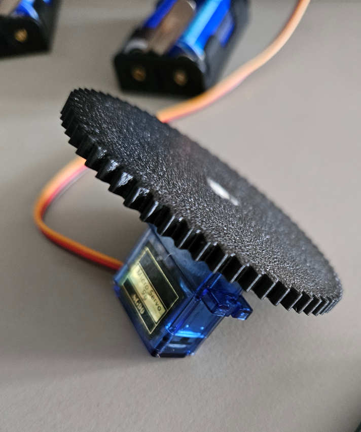
-I will be using a servo motor and an LED strip.-The servo motor will be used as a carousel, if you will, to spin a three-sided earring stand. To get more milage out of the servo motor, I will be 3D printing gears to have the earring stand make full rotations even with a servo only turning 180 degrees. The gear on the servo will have 64 teeth, while the gear it will be interacting with, connected to the rotating part of the stand will have 16 teeth. With this ratio of 4:1 the stand will make two full rotations in one direction and then another two in the opposite direction when the servo returns to place.

-The LED strip will be used to light up the stand, with a duel purpose of providing sufficient lighting if it is dark out and to also place a spotlight/ highlight the earrings being showcased. The LED strip will be sandwiched in between two wooden decorative frame pieces that go around the rotating stand part.
Inputs
-The motion sensor is the main interface and intended interaction with the piece. The motion sensor will control the servo motor. The idea of this piece is to draw in more viewers. If people are walking in crowds from a distance, they might not even notice small items such as earrings. The idea is, the motion from the stand moving would be intriguing from a far and draw spectators closer in. If people are coming in for a closer look at earrings, I don’t want the display to be moving. So, when the motion sensor is triggered, the stand will stop rotating.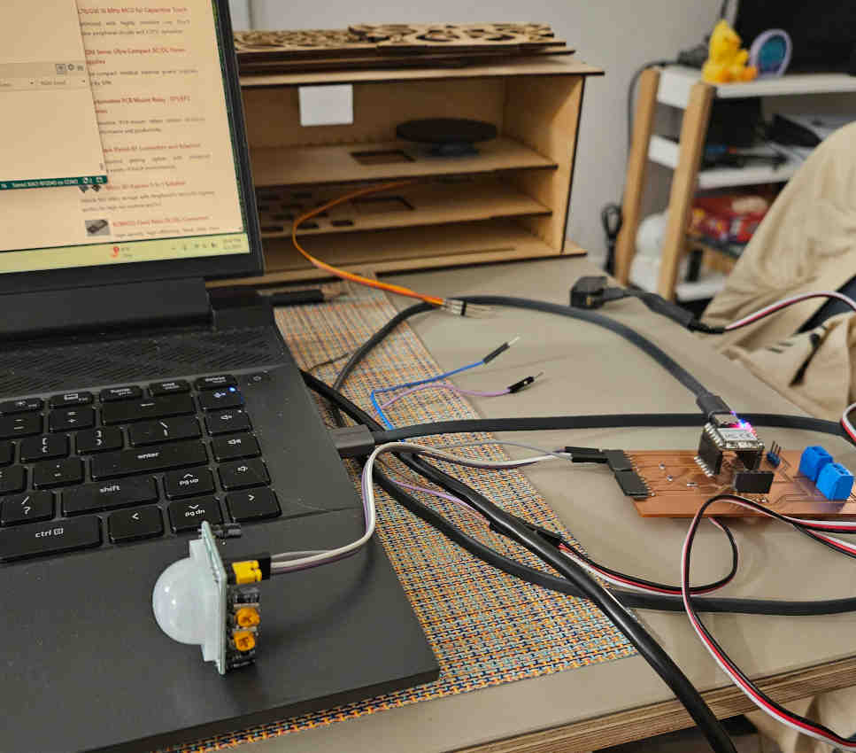
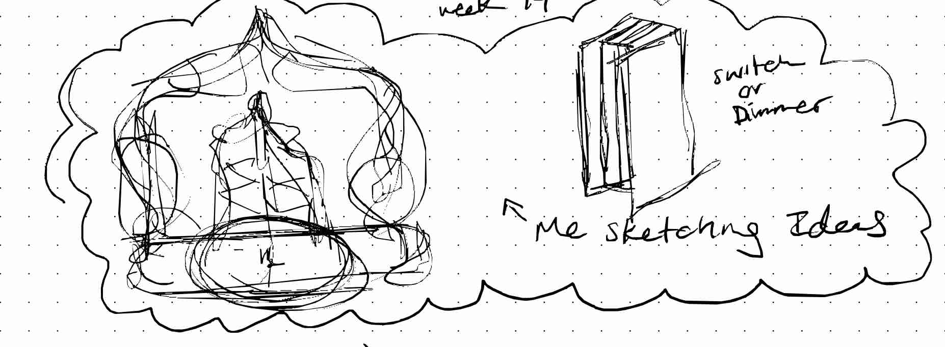
- I may or may not include rocker switches as additional override controls for the servo and LED strip.
Board
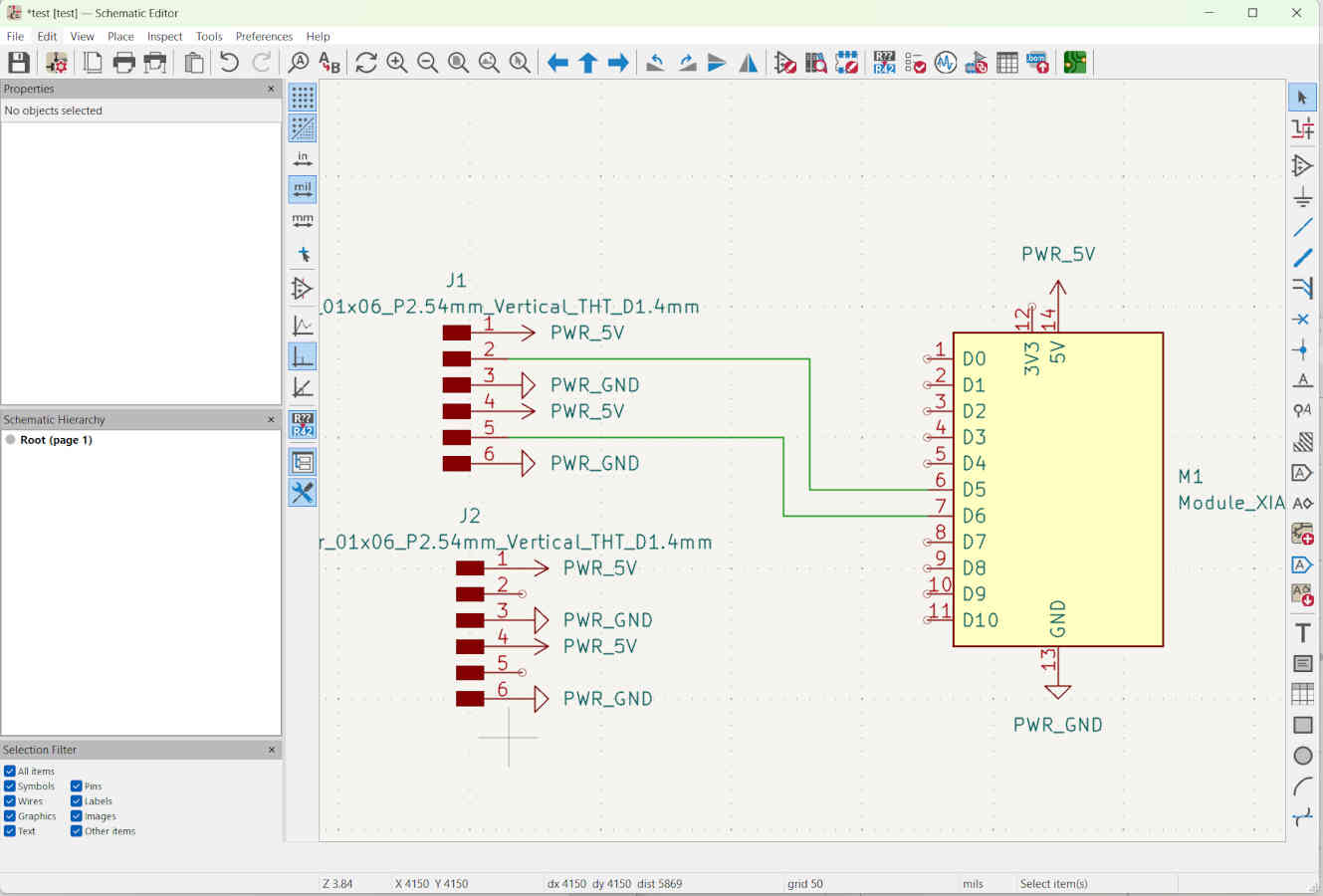
- While I had accounted for my two inputs and outputs in my original board, I did not account for the knowledge and information I had lack. Before purchasing all the components, in my ignorance I thought all components has three connections. Since then, I have designed a board to adjust for the aspects I had not considered.-Old schematic and board
-New schematic
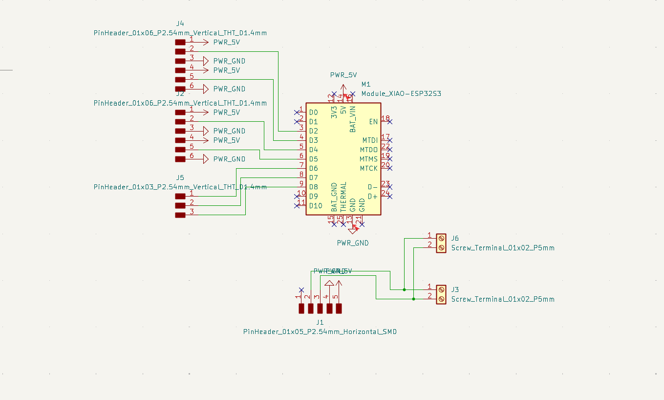
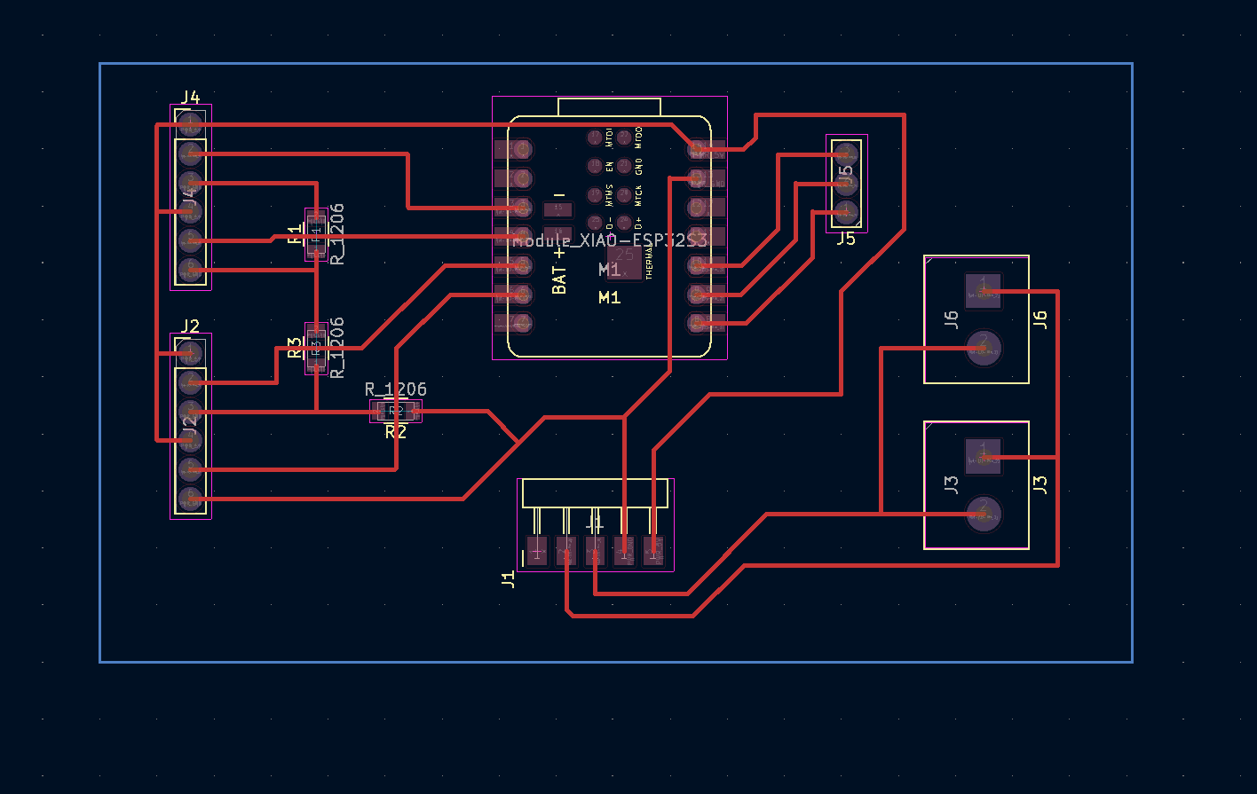
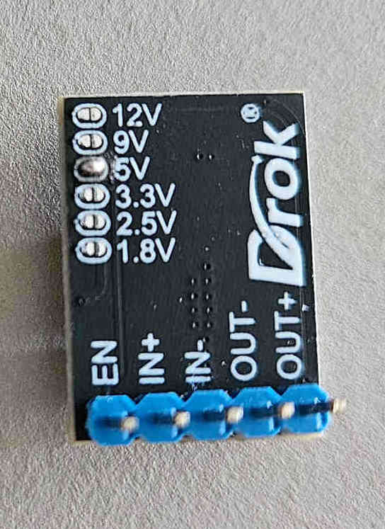
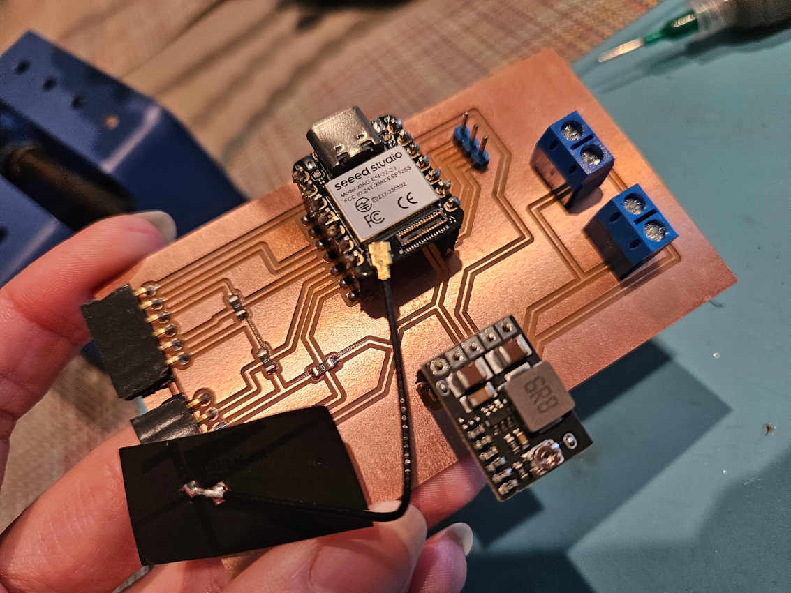
- The LED strip has not one, but three signal connections. The LEDs are also 12v. I needed to add additional power as well as a buck converter to control the voltage distribution to the LEDs and the microcontroller. I will be using 8 AA batteries in a 12v battery pack using the buck converter to make sure the LEDs will receive 12v coming in and have 5v going out to the ESP32s3 controller, which will in turn power the rest of the components.
Structure
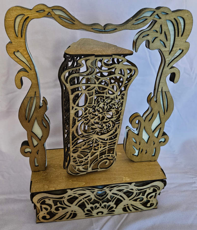
- I have created an interlocking housing structure that discreetly covers all the electronics and mechanisms working the piece.
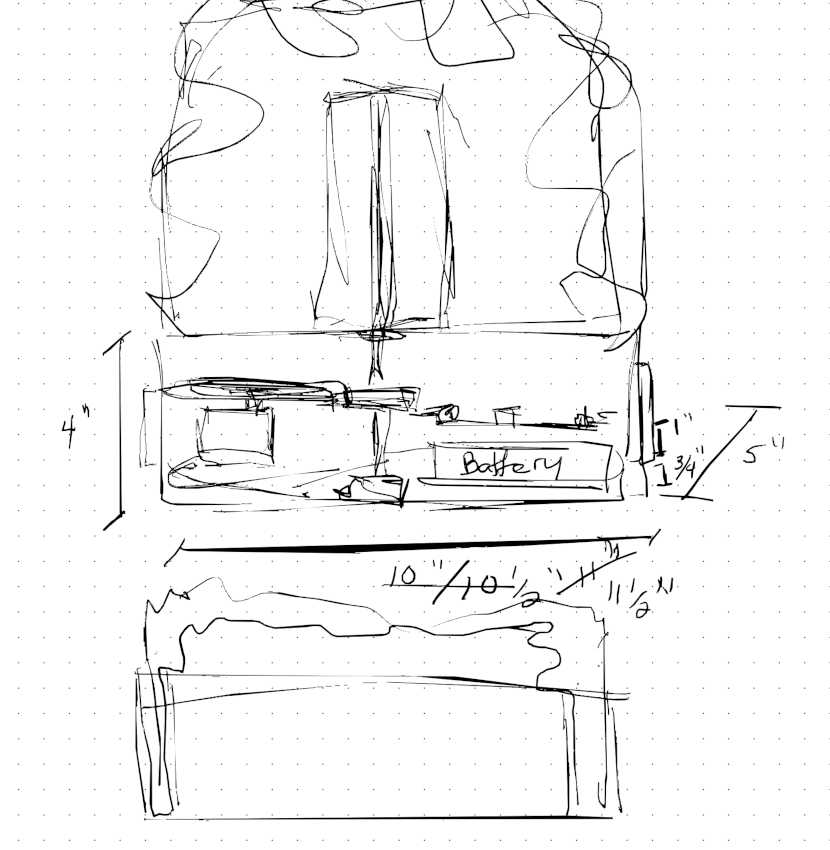
-There are two shelves in the box. One, for the battery pack and the second for the servo and PCB board. Both shelves have a hole cut out of them for the dowel of the carousel to go all the way down to the base. Even though the batteries should not over heat, I designed the box so the battery pack isn’t directly on the base and has air holes cut in the shelf to keep cool and stay light weight.
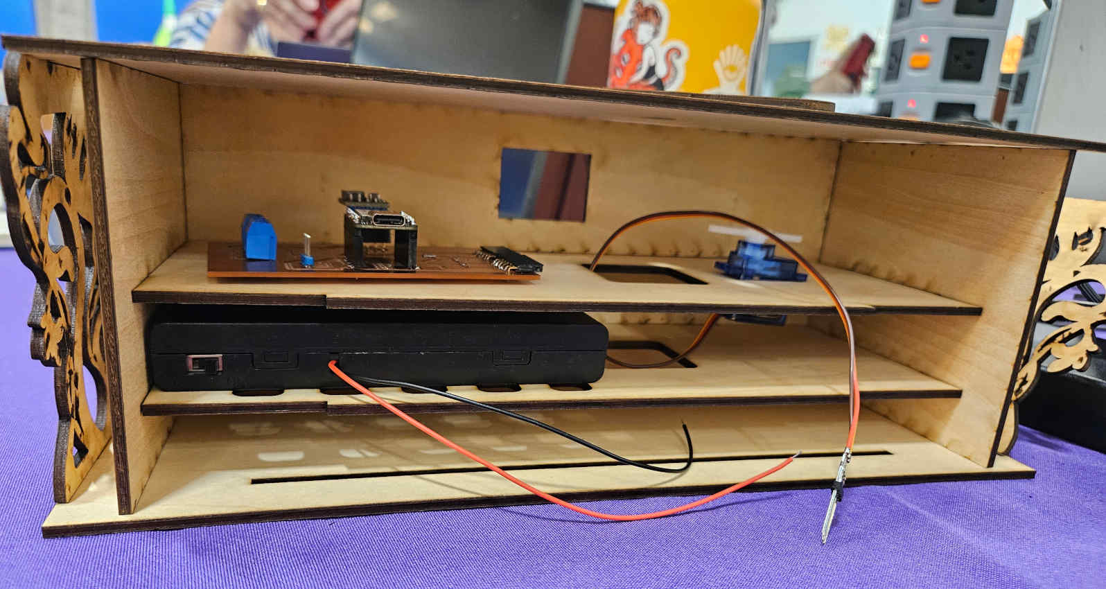
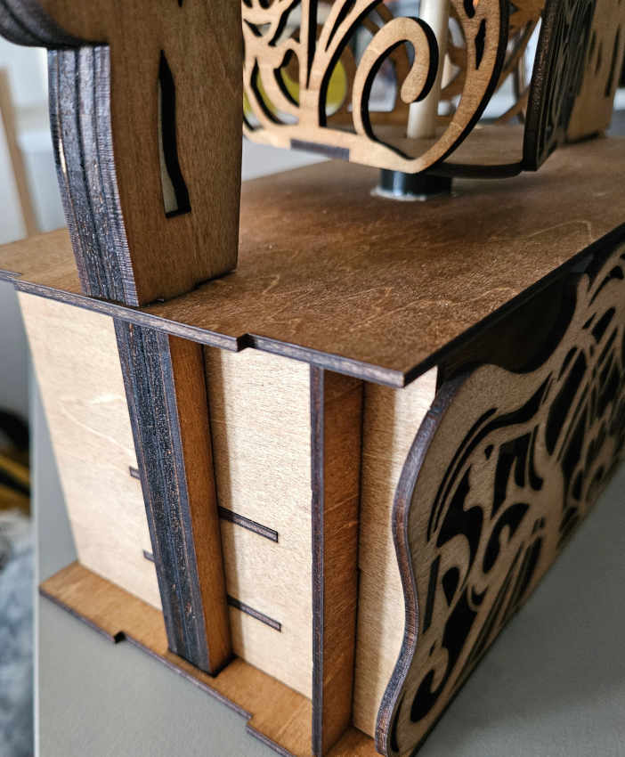
-The dowel will sit in a bearing at the base of the box. The gear for the dowel is press fit and moved into place to line up with the servo gear. There is another 3D printed press fit piece (not a bearing) inside the very top of the carousel. The dowel will fit into this piece and this is how the whole three-sided unit will move and not just the dowel. One more additional bearing is attached to the top of the base to add extra support to the carousel unit.
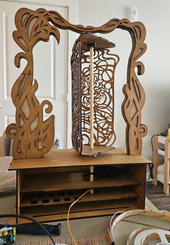
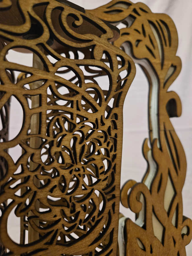
-For the arch around the carousel, to discreetly hide the LED strip without hindering the lighting, I designed it to be a sandwich of wood paneling, similar to the idea of a hardcover book. You have the front and back cover that sticks out a bit more, covering/protecting the shorter pages.


-The front panel has a hole cut out of it for the motion sensor to be placed in the front. The majority of the interlocking of the pieces adds structure to the whole piece. The arch slides in from the top of the base and goes through, all the way down to the bottom of the base sitting in a notch to prevent sliding and movement.
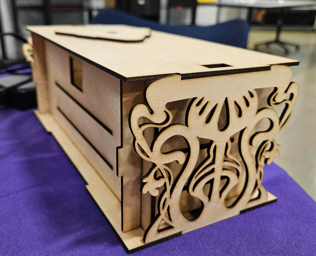
-To make the outside of the base look extra finished, I added decorative panels to the sides and front. The front design was created with motion sensor placement in mind.