Week 10 : Output Devices
As a natural progression from last week, which was inputs, this week is outputs week! Our goal for the week is to add an output device to a microcontroller board we have designed and program it to do something. As a group we need to measure the power consumption of an output device.
Output Devices
This week has been a bit of an overview week, having already played with outputs last week as well as electronics production week. I’ll be using a servo motor as my output device since that will be one of the components I intend to use for my final project.
-There are three main types of servos.-
Ex: Useful for limited-range applications like moving levers or steering linkages
-
Ex: Useful for wheels and gears
-
Ex: Useful in larger droids, robots, and machinery
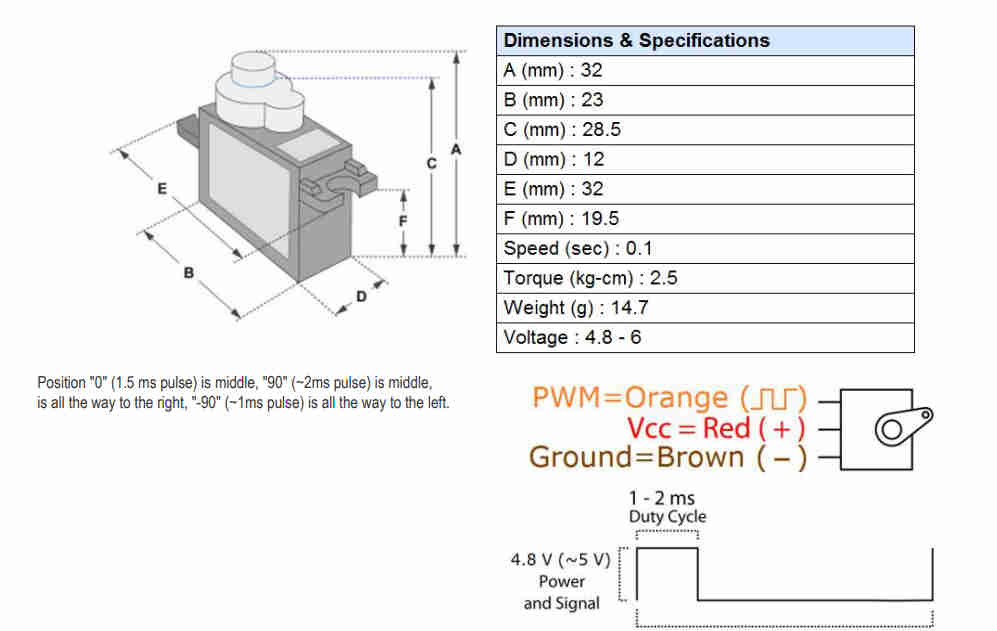
- The servo I will be using this week is the SG90 Servo, which is a positional rotation servo. This particular servo is small and lightweight with decent output power. It can rotate approximately 180 degrees (90 in each direction). You can use any servo code, hardware or library to control it. It also comes with a few different arms/hardware attachment options.

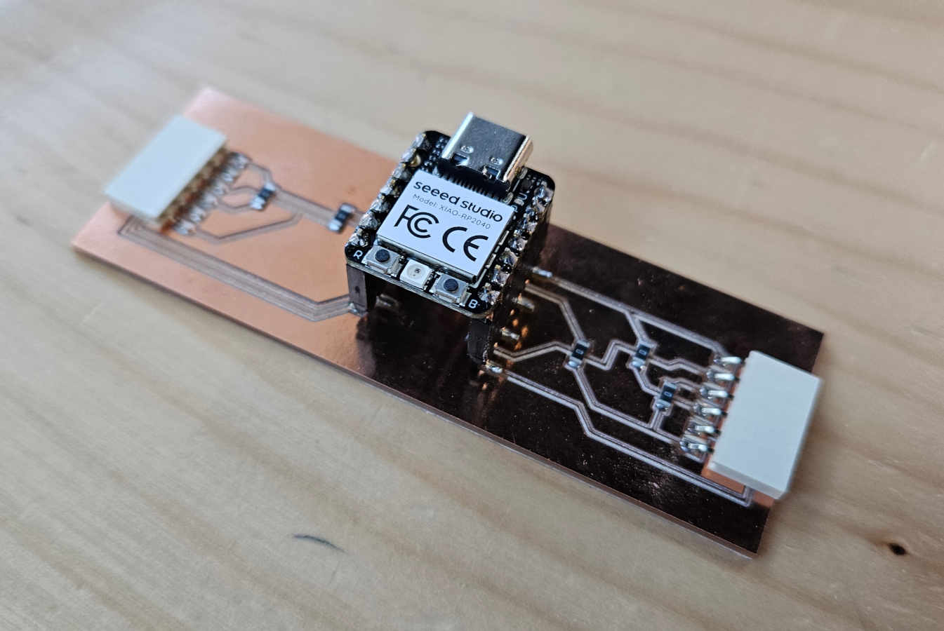
- I will be connecting this servo to the PCB board I originally milled back in electronics production week. After having working on this board the past two weeks and having gained a lot more insight from the group assignment, I have come to the conclusion that I will eventually designing a new board for the final project. Discussing power and power consumption, I realized I’ve been over looking power completely for my final project. I will be considering what batteries and setup will be needed to house everything within my project without it needing to be plugged into the computer or a wall outlet.

- I am using the code I had pulled together from last week, which will have the servo interact with a roller switch. When the switch is clicked once, the servo will move from the 0 degree position to 90 degrees and back four times.
#include < Servo.h >

        Servo myServo;
        int var = 0;
        const int switchPin = D7;  // Define the switch pin
        const int servoPin = D8;   // Define the servo pin

        void setup() {
          pinMode(switchPin, INPUT_PULLUP);  // Set switch as input with pull-up resistor
          myServo.attach(servoPin, 600, 2400);
        }

        void loop() {
          if (digitalRead(switchPin) == LOW) {  // Check if switch is pressed
            var = 0;  // Reset var to allow movement

            while (var < 4) {
              // Move from 0° to 90°
              for (int pos = 0; pos <= 90; pos += 1) {
                myServo.write(pos);
                delay(10);
              }

              // Move back from 90° to 0°
              for (int pos = 90; pos >= 0; pos -= 1) {
                myServo.write(pos);
                delay(10);
              }

              var++;
            }
          } else {
            myServo.write(0);  // Keep servo at 0° when switch is not pressed
          }
        }
- Here you can see the signal waves and how the voltage changes while moving and changing positions when activated.

Group Assignment
This week's group assignment consisted of measuring the power consumption of an output device. Power consumption is calculated using the formula Power (P) = Voltage (V) x Current (I). Power is measured in watts, V in volts, and current in amps.
-Both Vicky and Augusto have been using servos so they decided to measure the power consumption of a servo motor.-To measure power consumption we first used a multimeter. From the video you can see that starting and stopping the servo motors creates a drop in the voltage readings. When off the voltage readings are set around 7.5-7.52 volts. But when operating, the three servos drop the voltage between 7.38-7.42 volts. While interesting seeing the effects of on/off output devices, we realized that we still needed to obtain an amps reading to calculate power consumption. For this reason we decided to switch over to the DC Power Supply we had in the space, which can provide voltage and amperage readings while also calculating wattage consumed for you. Additionally we started off by removing two of the three servos so we could establish the averages for just one first.
-To use the DC Power Supply, we made sure to hook up the red clamp to the power line and the black clamp to the ground line. Using the power supply we could choose how many volts and amps the power supply was providing to the board. We maxed out the amps at 3.23 and we chose three different voltage levels to focus on with our one servo.
Throughout these tests we realized that increasing voltage would increase amperage. Upon further research we learnt that this was an effect of Ohm’s Law. Since our resistance had remained constant throughout testing of the board and its outputs, the volts had remained directly proportional to the amps.