Input Devices
Back to HomeGoals
group assignment
- probe an input device's analog levels and digital signals
Individual Assignment
- measure something: add a sensor to a microcontroller board that you have designed and read it
Group Assignment
Introduction to Analog and Digital Signals
What are Analog and Digital Signals?
In electronic systems, input devices generate two types of signals: Digital Signals and Analog Signals. Understanding their differences is fundamental for electronic design and programming.
What is a Digital Signal?
A digital signal is a discrete signal that has only two states:
- HIGH (1) – usually 3.3V or 5V
- LOW (0) – 0V
It functions like a switch: only on or off.
Characteristics:
- Only two values (0 or 1)
- Stable and noise-resistant
- Read with:
digitalRead()
- Used in: buttons, limit switches, IR detectors, etc.
digitalRead()Example: A push button outputs 0 when pressed, 1 when released.
What is an Analog Signal?
An analog signal is a continuous voltage signal that represents a range of values such as brightness, temperature, or position.
Its voltage can vary smoothly between 0V and 3.3V (or 5V), allowing more detailed input.
Characteristics:
- Continuous value range
- Can express fine physical changes
- More sensitive to noise
- Read with:
analogRead() - Used in: potentiometers, LDRs, temperature sensors, microphones
Example: A potentiometer outputs varying voltage depending on rotation.
Comparison Table
| Feature | Digital Signal | Analog Signal |
|---|---|---|
| Type | Discrete (0 or 1) | Continuous |
| Information | Simple on/off | Detailed variation |
| Noise Resistance | High | Low |
| Reading Function | digitalRead() | analogRead() |
| Example Devices | Button, IR switch | Potentiometer, LDR |
Why is this important?
In real-world projects, both analog and digital inputs are used together. For example, you might use a button (digital) to start a process and a potentiometer (analog) to adjust intensity. Knowing how to handle both types correctly is essential in interactive electronics and embedded systems.
Objective
The goal of this group task was to understand and probe analog signals using a simple input device. We chose a potentiometer (rotary knob sensor) to demonstrate how analog signals behave and how they can be read using the XIAO ESP32S3 development board.
Introduction to the Potentiometer
The potentiometer is a three-pin variable resistor. It acts as a voltage divider by providing a continuously variable voltage at its middle pin depending on the knob's rotation.
- Left and right pins: connected to 3.3V and GND
- Middle pin: outputs a voltage between 0V and 3.3V
- This voltage is read by an analog pin (A0) of the ESP32S3
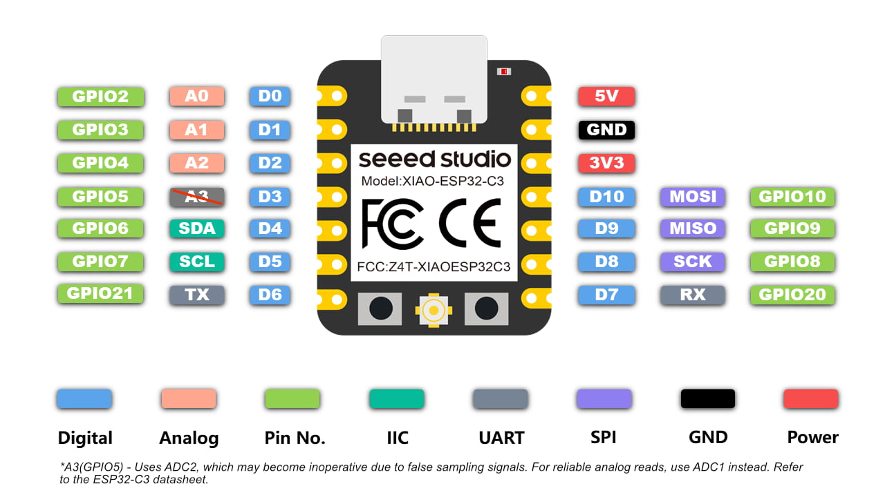
Wiring
| Potentiometer Pin | Function | ESP32S6 Connection |
|---|---|---|
| Left | GND | GND |
| Middle | Analog Output | A0 |
| Right | 3.3V Power | 3.3V |
Note: The outer pins can be reversed; the result will only change the direction of increase/decrease.
Arduino Code
void setup() {
                Serial.begin(115200);
                }

                void loop() {
                int rawValue = analogRead(A0);
                float voltage = rawValue * (3.3 / 4095.0);
                Serial.print("Analog Value: ");
                Serial.print(rawValue);
                Serial.print("    Voltage: ");
                Serial.println(voltage, 2);
                delay(200);
}Experiment Steps
- Connect the potentiometer to the ESP32S3 as shown above.
- Upload the Arduino sketch to the board.
- Open the Serial Plotter in Arduino IDE.
- Slowly turn the knob and observe the output values and curves.
Observations
| Knob Position | Analog Value | Voltage |
|---|---|---|
| Far Left | 0 | 0.00 V |
| Center | ~2048 | ~1.65 V |
| Far Right | ~4095 | ~3.30 V |
The Serial Plotter shows a smooth, continuous curve. The analog value increases linearly with the knob rotation.
Group Discussion and Conclusion
| Feature | Description |
|---|---|
| Signal Type | Analog (continuous) |
| Output | Voltage from 0V to 3.3V |
| Reading Method | analogRead() |
| Response | Linear and smooth |
| Advantages | Simple, intuitive, perfect for analog input demo |
This experiment helped us clearly understand what an analog signal is and how a microcontroller like the XIAO ESP32S3 can read it. The potentiometer is an excellent demonstration tool for analog input behavior.
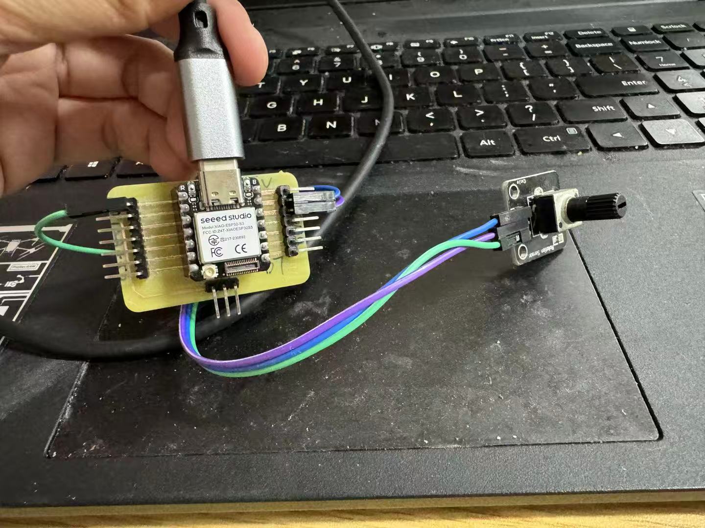
Button as Digital Input
A push button is a basic digital input device. It outputs only two states:
- LOW (0) when pressed
- HIGH (1) when released (using internal pull-up resistor)
Wiring
- One side of the button is connected to GND
- The other side is connected to D1 (GPIO2) on XIAO ESP32S6
- No external resistor is needed — we use
INPUT_PULLUP
Arduino Code
This code outputs both numeric and descriptive data so it's compatible with Serial Plotter and Serial Monitor.
const int buttonPin = D1;

              void setup() {
                pinMode(buttonPin, INPUT_PULLUP);
                Serial.begin(115200);
              }

              void loop() {
                int state = digitalRead(buttonPin);

                // Numeric output for Serial Plotter
                Serial.print(state);
                Serial.print("  -->  ");

                // Text output for Serial Monitor
                if (state == LOW) {
                  Serial.println("Pressed");
                } else {
                  Serial.println("Released");
                }

                delay(200);
              }
Observations
- Serial Monitor shows:
1 --> Released 1 --> Released 0 --> Pressed 0 --> Pressed 1 --> Released - Serial Plotter shows:
A square waveform that changes between 0 and 1 depending on button press.
Conclusion
The button provides a clear example of a digital input: two distinct states, perfect for detecting on/off events. The combined use of numeric and textual output allows for debugging in Serial Monitor and visualization in Serial Plotter, making this a flexible setup for input testing.
Individual Assignment
Assignment Requirement: "Measure something: add a sensor to a microcontroller board that you have designed and read its data."
Project Objective
This week, the input device I chose is the DHT11 temperature and humidity sensor. It is a digital sensor based on single-wire communication, capable of outputting both environmental temperature (Celsius) and relative humidity (%RH). I have integrated it into the microcontroller development board I am using, the Seeed Studio XIAO ESP32S3, and written a program in the Arduino IDE to read, output, and visualize the data.
This project helped me achieve the following goals:
- Master the communication principles of digital sensors (single-wire protocol)
- Learn to collect data using library functions
- Use the serial monitor and plotter for real-time debugging and observation
- Create a complete "Perception - Processing - Display" input chain
What is an Input Device?
An input device is a component or module that converts information from the external physical world into electronic signals, playing the role of "perception" in an electronic system. It can be a button, thermometer, light-dependent resistor, potentiometer, etc.
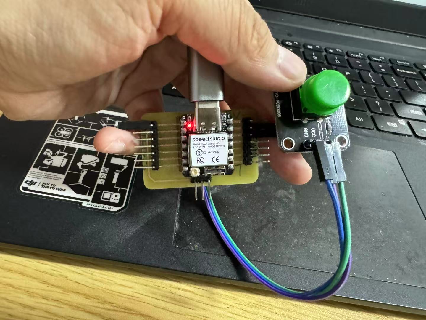
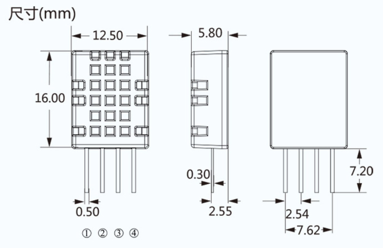
DHT11 Overview:
The DHT11 is a common digital temperature and humidity sensor. It is encased in a blue plastic shell and contains:
- An NTC thermistor (for temperature measurement)
- A capacitive humidity sensor (for humidity measurement)
- A microcontroller (responsible for data collection and encoding)
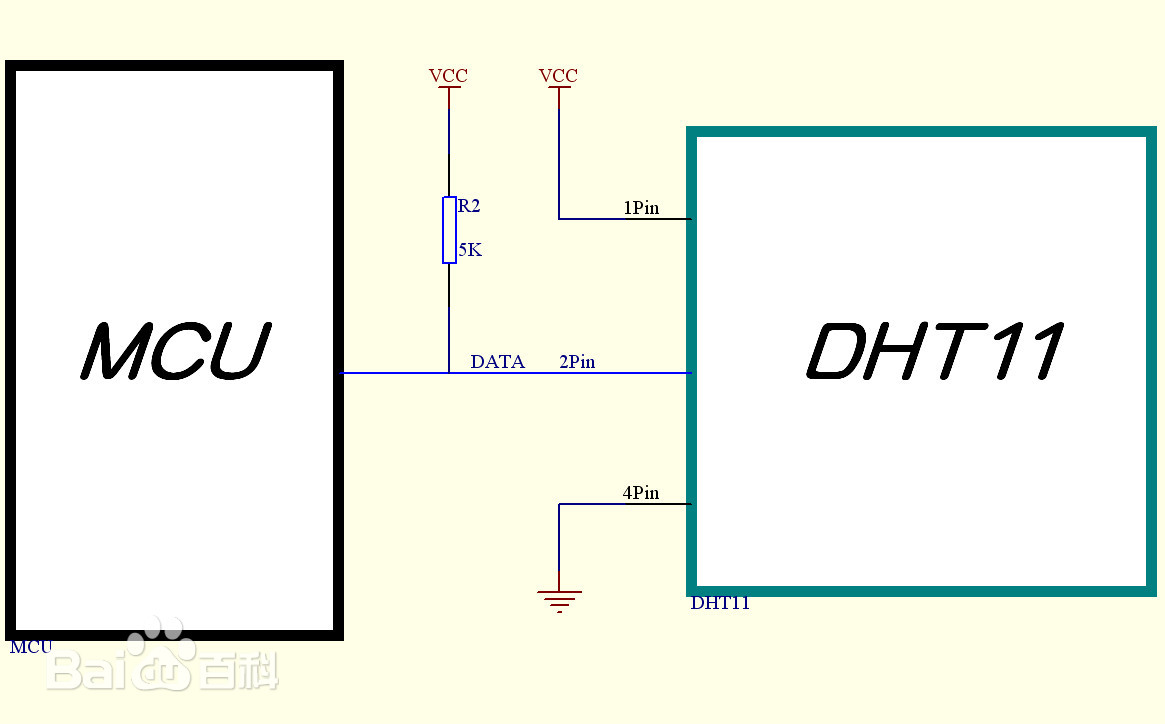
Its communication uses a dedicated single-wire protocol, with the microcontroller board communicating with the sensor via a data pin.
Hardware Components and Electrical Connections
Main Controller Board: Seeed Studio XIAO ESP32S3
- Main Chip: ESP32-S3 (Dual-core 240MHz)
- Supports both Arduino programming and ESP-IDF
- Compact size (21 x 17.5 mm), supports USB-C power supply
- Default operating voltage: 3.3V
- Equipped with multiple GPIO pins, analog inputs, and peripheral interfaces such as I2C, SPI, and UART
Sensor: DHT11 (Module Version)
| Pin Name | Function | Connected to XIAO ESP32S3 Pin |
|---|---|---|
| VCC | Power Input | 3.3V |
| GND | Ground | GND |
| DATA | Signal Output | GPIO3 (D2 on board) |

Software Environment and Development Process
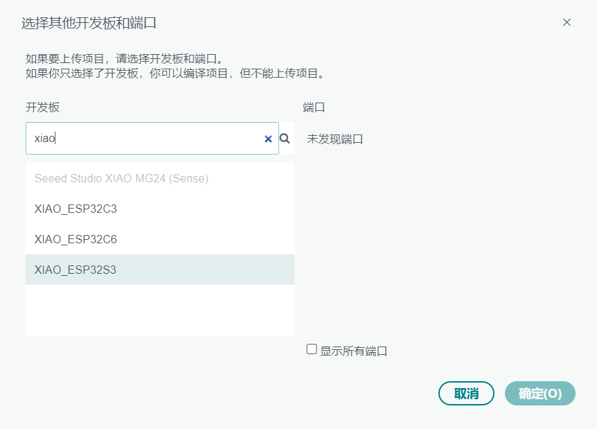
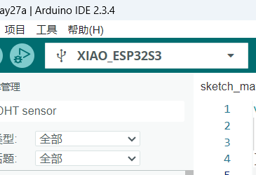
Arduino IDE Configuration Steps:
- Install Board Support Package: XIAO ESP32S3
- Open the IDE → Select Board → Type xiao → Choose xiaoesp32s3
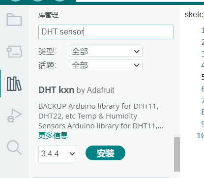
Install Required Libraries:
- Open Tools → Library Manager
- Search and install: DHT sensor library by Adafruit (and its dependency: Adafruit Unified Sensor)
Final Setup:
- Select board: Tools → Board → XIAO ESP32S3
- Select the correct port → Upload the code
Sample Code (Arduino IDE - DHT11 Sensor Reading)
#include "DHT.h" // Include the DHT library
#define DHTPIN 3 // Signal pin connected to GPIO3 (D2)
#define DHTTYPE DHT11 // Specify sensor type: DHT11
DHT dht(DHTPIN, DHTTYPE); // Create a DHT11 sensor object
void setup() {
Serial.begin(115200); // Initialize serial communication
dht.begin(); // Initialize the sensor
}
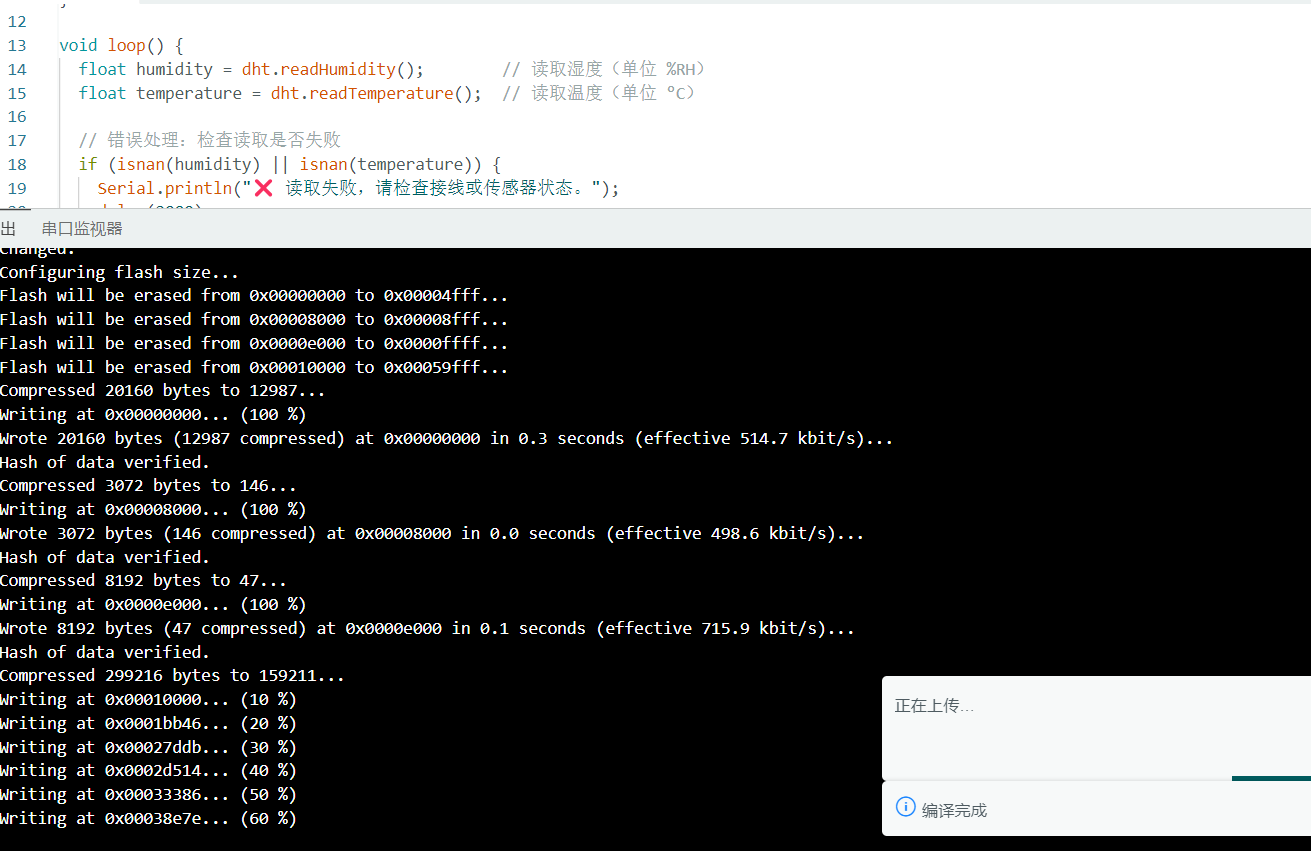
void loop() {
float humidity = dht.readHumidity(); // Read humidity (%RH)
float temperature = dht.readTemperature(); // Read temperature (°C)
// Error handling: check if reading failed
if (isnan(humidity) || isnan(temperature)) {
Serial.println("❌ Failed to read from sensor. Please check wiring or sensor status.");
delay(2000);
return;
}
// Output for Serial Plotter (to draw graphs)
Serial.print(humidity);
Serial.print(",");
Serial.println(temperature);
// Output for Serial Monitor (human-readable)
Serial.print("✅ Humidity: ");
Serial.print(humidity);
Serial.print("% Temperature: ");
Serial.print(temperature);
Serial.println(" °C");
delay(2000); // Recommended reading interval ≥ 2 seconds
}
Experiment Process and Data Observation
After uploading the program, I opened the Serial Monitor and Serial Plotter to perform the following test:
✅ Normal Reading:
✅ Humidity: 58.00% Temperature: 26.60 °C
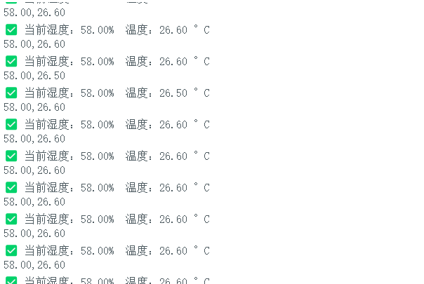
Experimental Intervention:
- Exhaled onto the sensor to simulate a high-humidity environment — humidity quickly rose to around ~70%.
- Placed a hand near the sensor — temperature gradually increased.
- After removing the hand and stopping exhalation — both temperature and humidity returned to baseline.
Error Handling Strategies
| Issue | Possible Cause | Solution |
|---|---|---|
Read failure / Output shows nan |
Incorrect pin setting, damaged module, or interval too short | Check GPIO configuration; increase delay to more than 2 seconds |
| Garbled output / No data displayed | Serial baud rate mismatch | Ensure Serial.begin() matches the serial monitor settings |
| Data not updating | Sensor not responding or stable air conditions | Trigger sensor by exhaling or applying heat |
Conclusion and Reflection
Through this experiment, I successfully completed the individual assignment for the Fab Academy's "Input Devices" module. This task not only involved physically connecting a real sensor (DHT11), but also gave me a clearer understanding of the entire process from "sensor → data reading → information display."
Specifically, I:
- Successfully integrated the DHT11 temperature and humidity sensor into the control system I was using;
- Learned how to communicate with the sensor via a single-wire digital protocol, and understood its timing requirements;
- Completed the wiring, uploaded the program, and stably read data using the XIAO ESP32S3 board;
- Mastered how to format output data so that both the serial monitor and plotter could display results properly;
- Encountered read failures during debugging, but solved them by consulting documentation and adjusting the delay;
- More importantly, I gained a real understanding of the full chain from "physical phenomenon → electrical signal → digital data → visual output."
Although this sensor is relatively basic, through hands-on practice I developed a more intuitive grasp of how input devices work and what role they play in a system.