Computer-Controlled Machining
Back to HomeGoals
group assignment
- do your lab's safety training
- test runout, alignment, fixturing, speeds, feeds, materials,and toolpaths for your machine
Individual Assignment
- make (design+mill+assemble) something big (~meter-scale)
- 3extra credit: don't use fasteners or glue
- extra credit: include curved surfaces
Group Assignment
Lab Safety Training
Before beginning CNC work, I completed the safety training session provided by our lab. The training included:
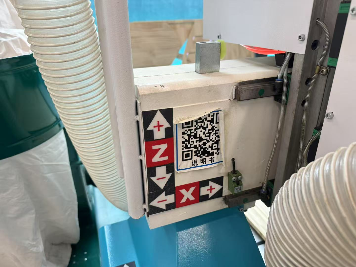
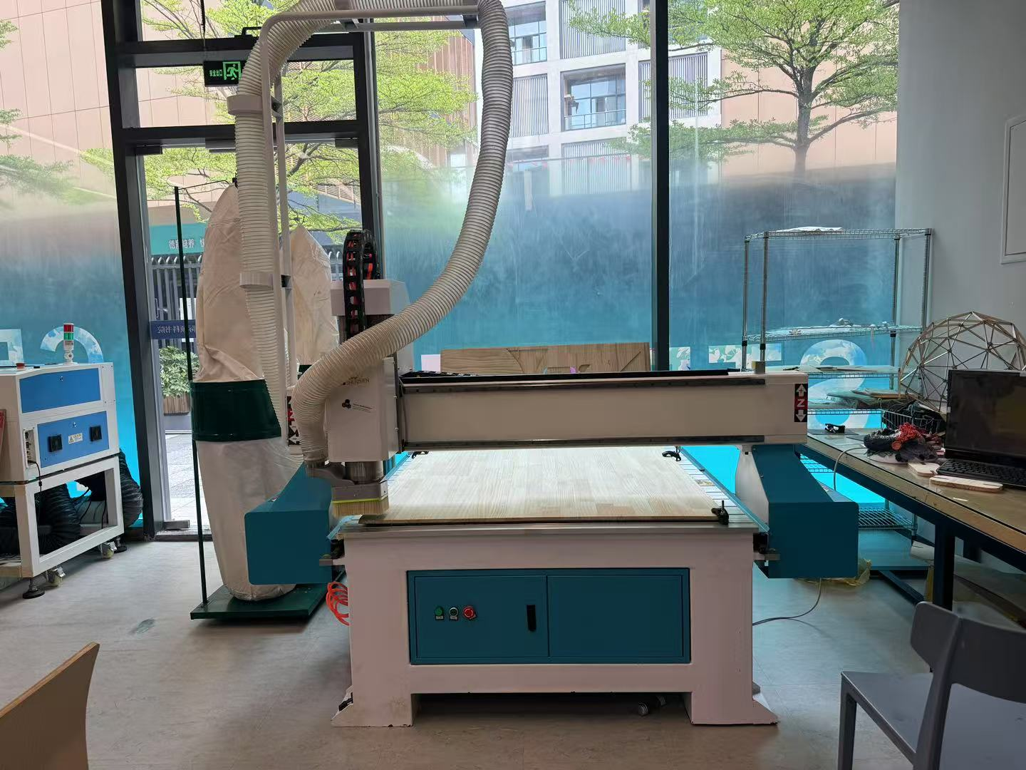
Equipment Overview
- Reading the product manual
- Understanding the basic structure and operating principles of the CNC machine
Pre-Operation Precautions
- Check equipment model and accessories upon unpacking
- Place the machine on a stable, level surface
- Ensure all accessories are installed correctly
- Do not operate in high-interference environments
- Prevent conductive materials from entering the system
- Machine must be properly grounded
- Avoid water, dust, and fire
- Do not use corrosive solvents on spindle/tool
- Keep hands and cloth away from rotating tools
- Maintenance only under manufacturer guidance
Operational Safety Guidelines
- Ensure machine is level and fixed
- Connect to the correct voltage
- Wear proper clothing; no gloves or loose hair
- Stay clear of moving parts
- Turn off power before cleaning
- Inspect only when power is off
- Keep power cables out of walking paths
- Avoid overloading outlets
- Do not insert foreign objects into the machine
- Avoid using during thunderstorms
Machine Specifications
- Voltage: 220V (380V optional)
- Spindle power: 3KW
- Spindle speed: 24,000 RPM
- Max work area: 1300 × 2500 mm
- Z travel: 200 mm
- Controller: Weihong system
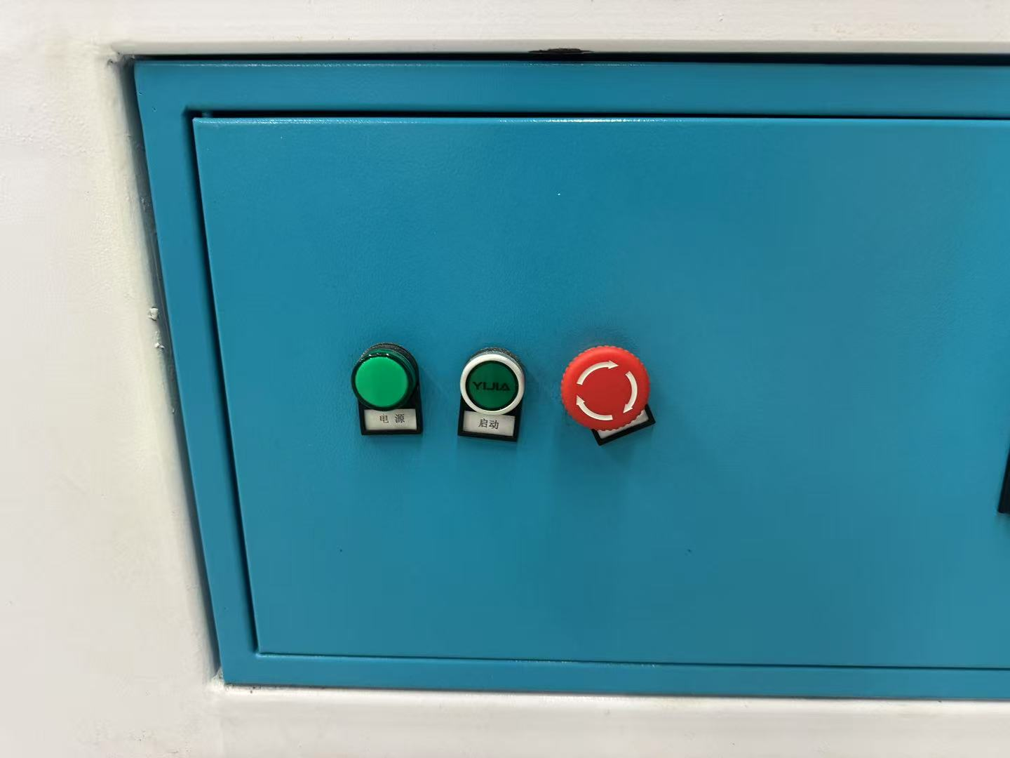
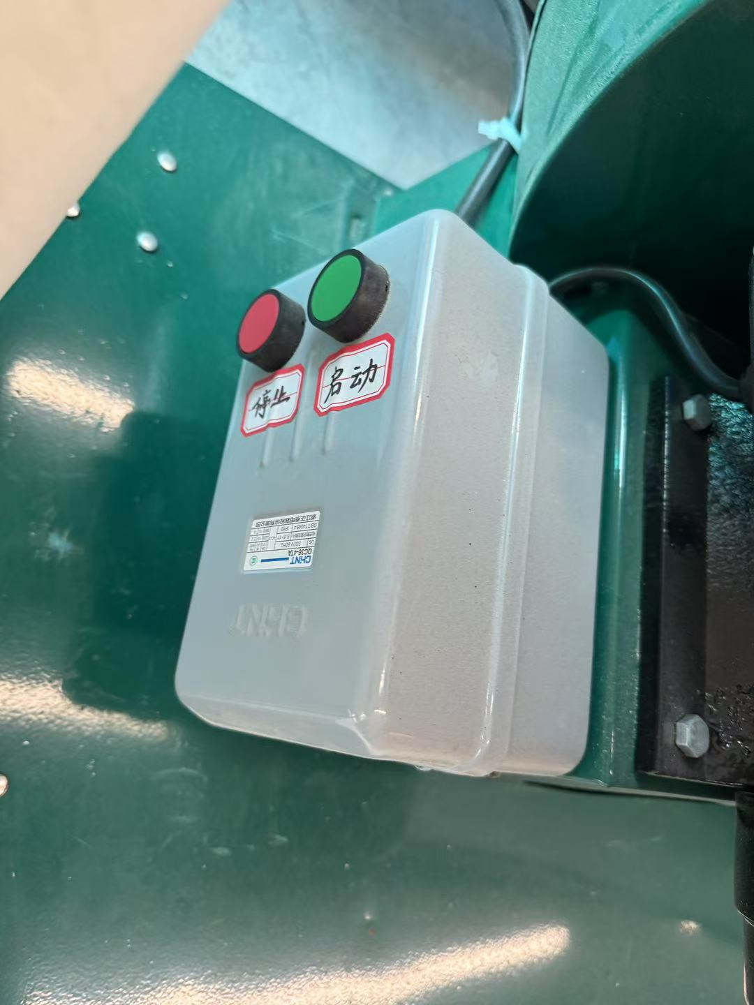
Operation Essentials
- Startup/shutdown procedures
- Emergency stop button usage
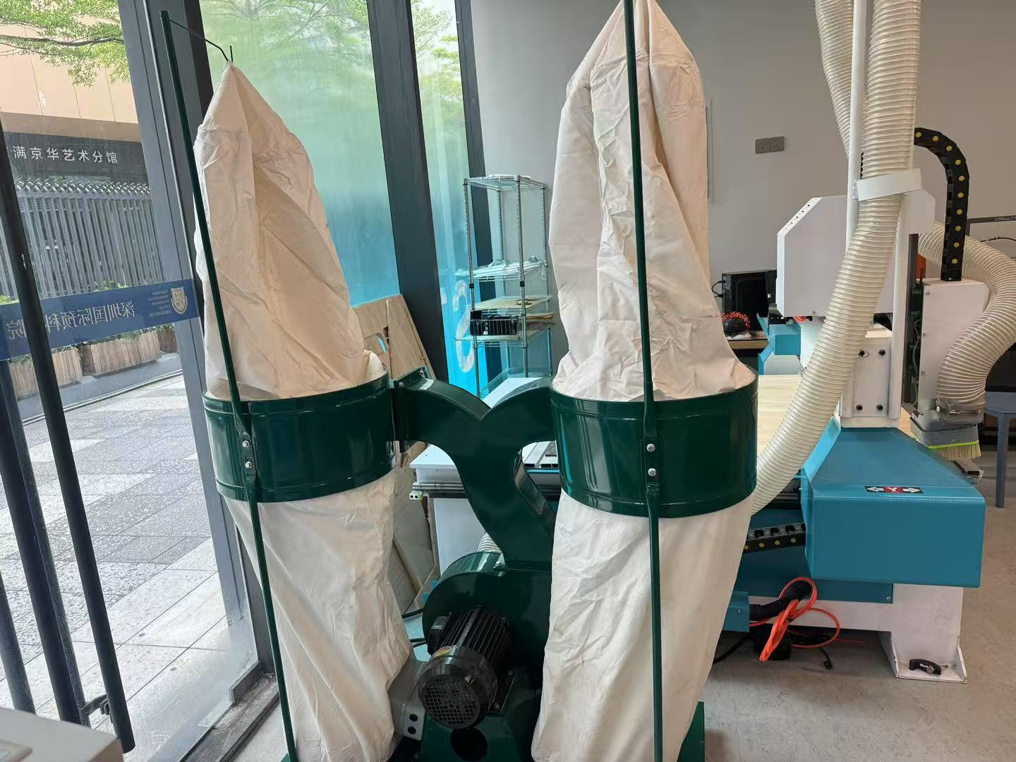
- Dust collection system activation
- Proper fixturing of materials
CNC Machine Testing
1. Spindle Runout
Measured with a dial indicator — approx. 0.008 mm (acceptable range)
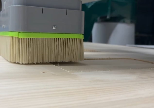
2. Machine Alignment
Flattened spoilboard with a surfacing bit — result was even with no ridges
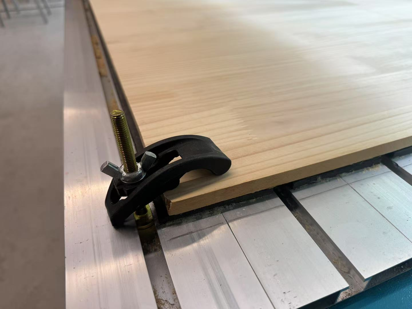
3. Fixturing
- Screws into spoilboard (most secure)
- Side clamps (reusable setups)
- Final method: screws + side clamps
4. Speeds & Feeds Test
| Parameter | Value |
|---|---|
| Tool | 6mm flat-end mill |
| Spindle Speed | 16,000 RPM |
| Feed Rate | 1200 mm/min |
| Plunge Rate | 300 mm/min |
| Cut Depth | 3 mm/pass |
Results: clean edges, no burning, smooth operation
Individual Assignment
Task: Make (design + mill + assemble) something big (~1 meter scale)
Extra credit: Don’t use fasteners or glue | Include curved surfaces
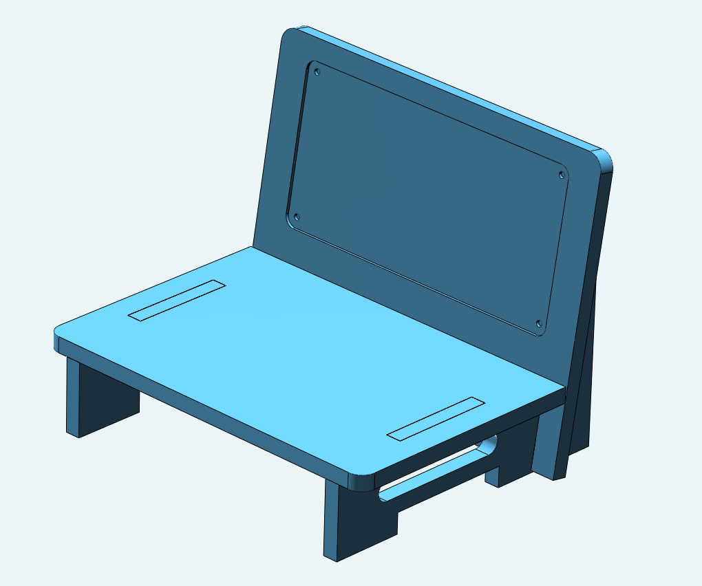
Project Idea
For this week's assignment, I decided to create a display stand for Litchee Lab. I began by measuring the available space to determine the approximate size of the structure. Based on that, I moved on to 3D modeling and design.
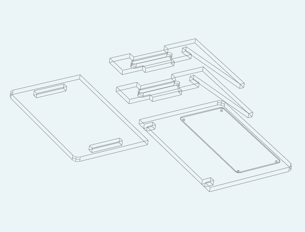
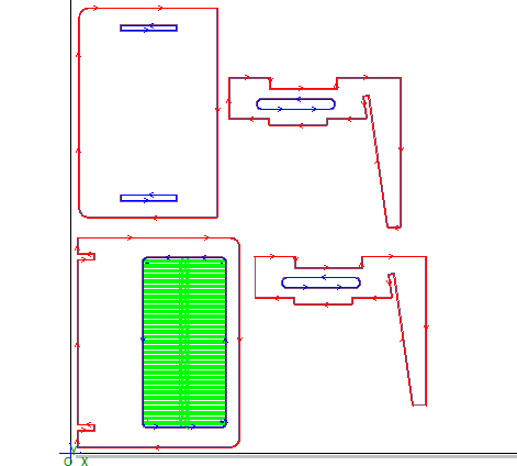
Design and Toolpath Setup
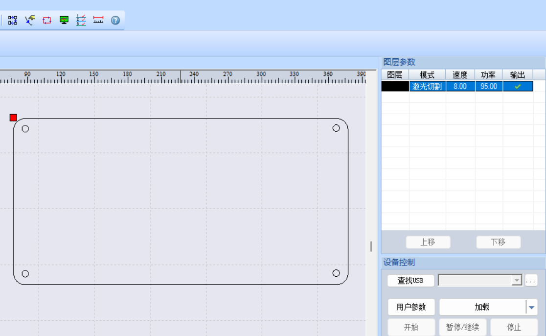
Although the CNC machine supports both 2D and 3D files, I chose to export 2D vector drawings for this project. The design included both cutting and engraving operations. I set different toolpaths for these areas using CAM software, which automatically generated the corresponding G-code files.
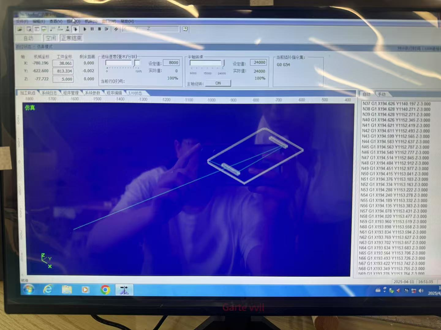
Software Workflow Challenges
One issue I encountered was the need to use two separate software tools—one for CAM and one for machine control. This seemed inefficient, and I wondered why the entire workflow couldn’t be completed within a single program.
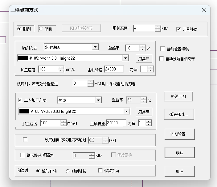
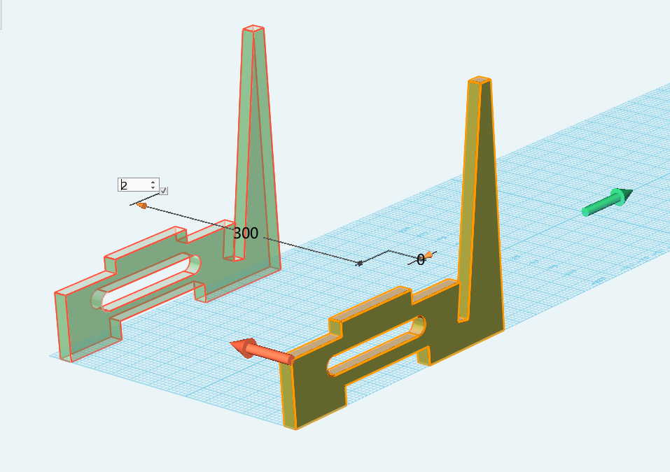
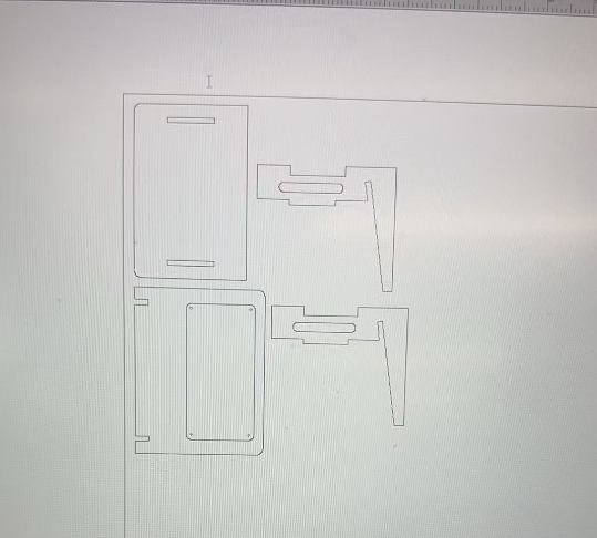
2D Engraving Settings (Translated Interface)
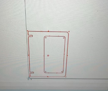
Additionally, on my first attempt, the origin point of the design was placed far from the actual geometry. I later realized that the lower-left corner of the design had to be aligned in the first software tool itself, which unfortunately provided no warning. This was another aspect I found quite unreasonable.
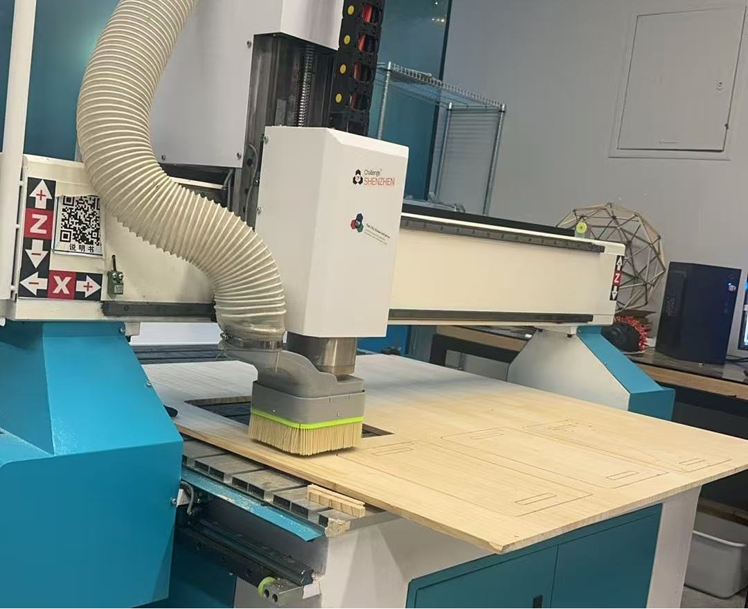
CNC Machining Process
After all preparations were complete, I finally started cutting the parts. The CNC machine was very loud during operation, but it worked as expected.
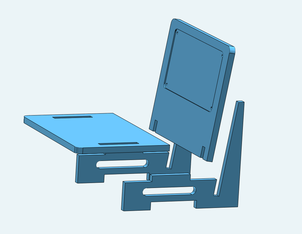
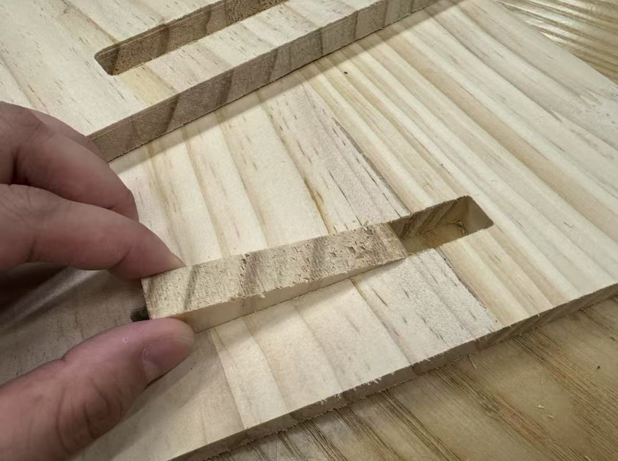
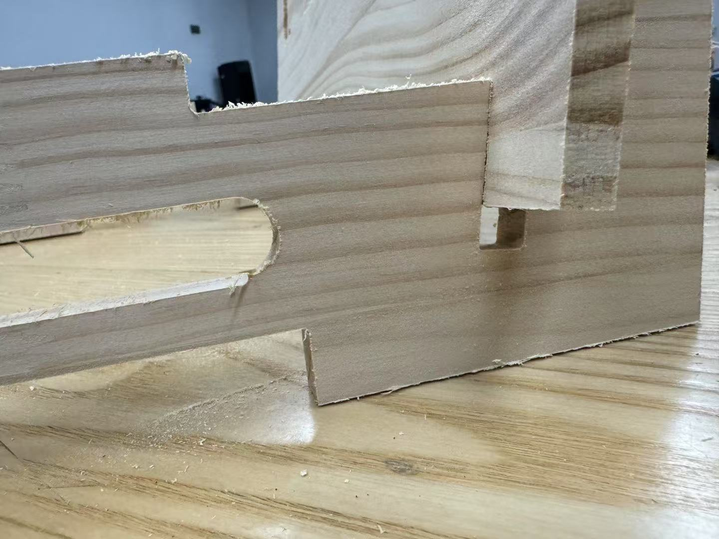
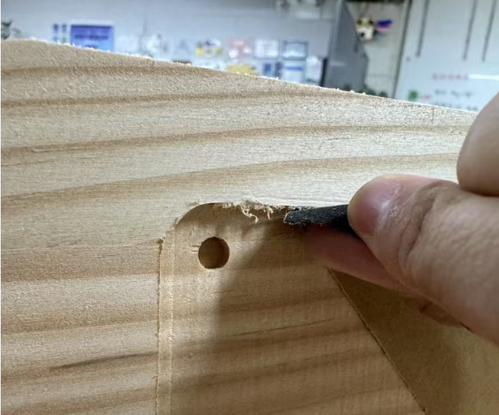
I paid special attention to groove dimensions because I had considered tool compensation during the setup phase. As a result, the parts fit together smoothly with a press-fit structure—no fasteners or glue needed.
Assembly and Finishing
Once all parts were milled, I assembled them into the full display stand. There were many burrs along the edges, so I carefully sanded them down to avoid injuries from sharp edges.
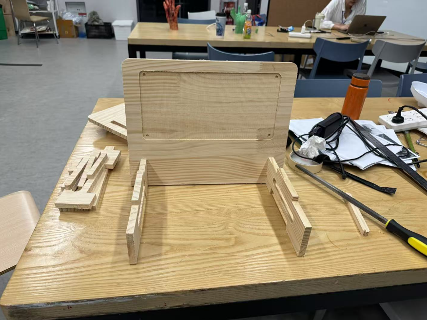
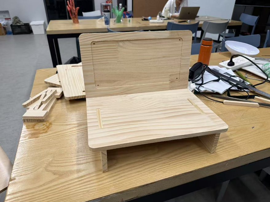
Additional Features
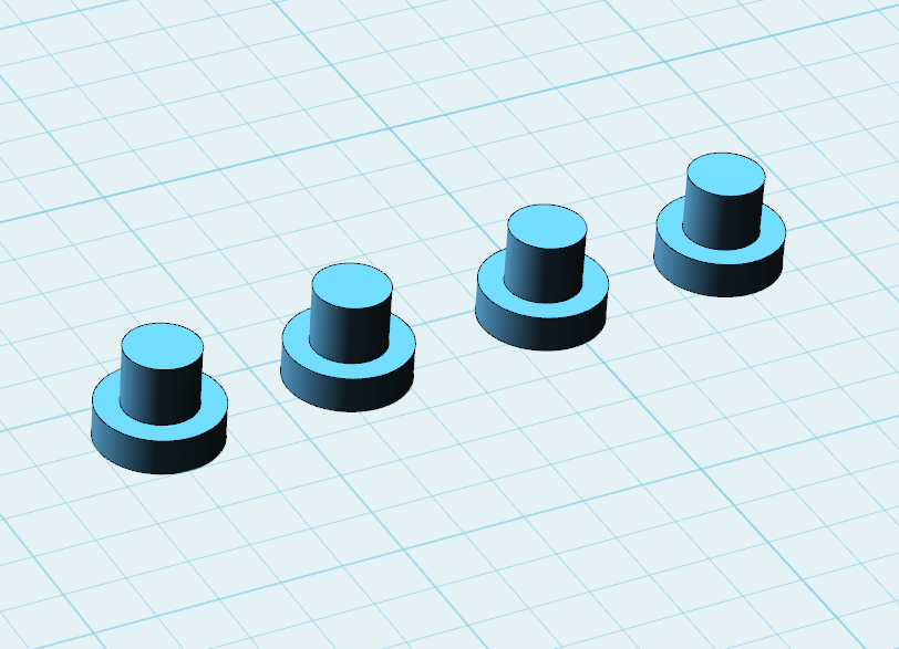
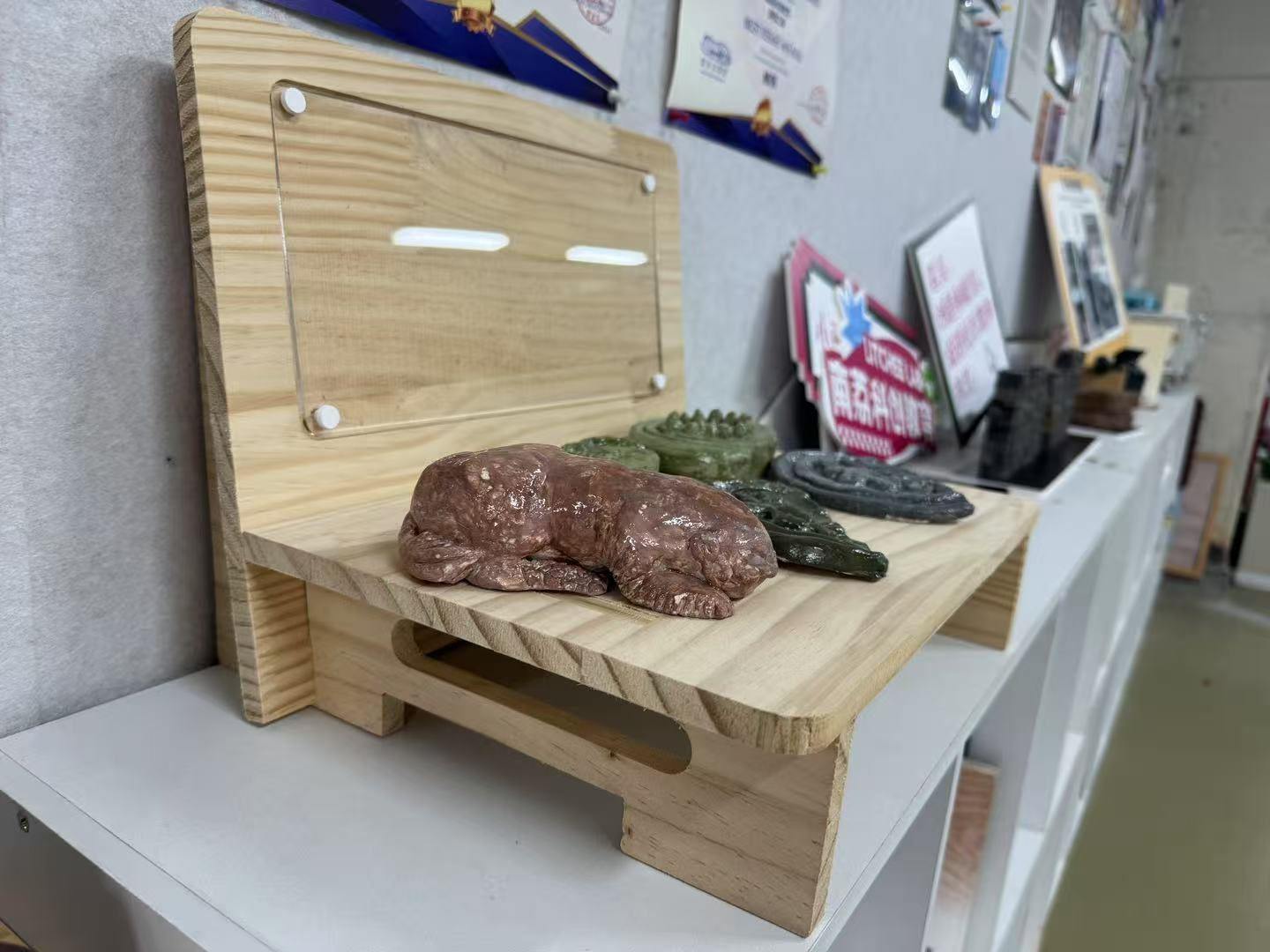
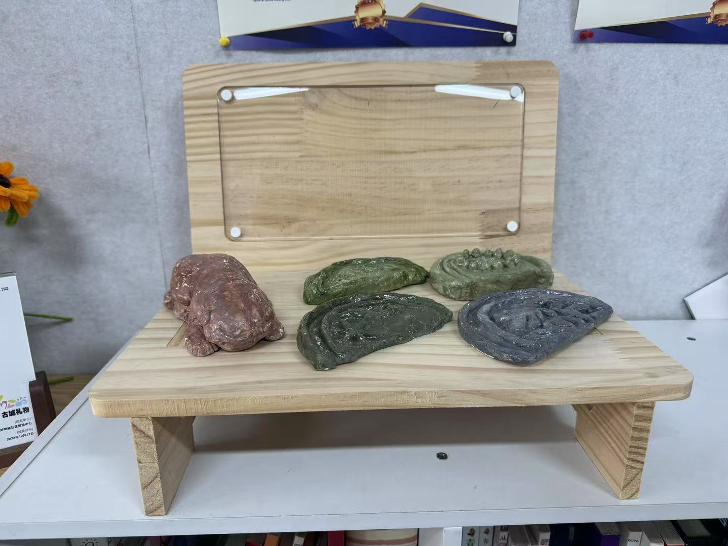
The stand includes a designated space for project descriptions. To finish it off, I cut a piece of acrylic for the nameplate and 3D-printed small pins to hold it in place.
Final Outcome
The project was successfully completed and resulted in a clean, sturdy, and presentable display stand, ready to be used in exhibitions!
Reflection
This week was both challenging and rewarding. Working with a large CNC machine for the first time pushed me to think carefully about safety, material handling, and toolpath precision. The group assignment helped me build a solid foundation in machine setup and operation, while the individual project offered a great opportunity to explore design for large-scale fabrication.
One of the biggest takeaways was the importance of workflow planning—especially when using multiple software tools. I encountered several unexpected issues related to file positioning and origin settings, but working through them gave me a deeper understanding of how CAM and CNC systems communicate.
I was also proud to achieve both extra credit goals: building a functional structure without fasteners or glue, and integrating curved features through press-fit and careful compensation. The noise and intensity of the machining process reminded me that digital fabrication isn’t just about design—it’s also about understanding machines as physical, sometimes unpredictable systems.
Overall, this week has strengthened my confidence in designing and fabricating at scale. I’m excited to explore more complex assemblies and possibly integrate CNC with other digital fabrication tools in future projects.