Embedded Programming
Back to HomeGoals
Group assignment:
- Demonstrate and compare the toolchains and development workflows for available embedded architectures.
- Document your work to the group work page and reflect on your individual page what you learned.
Individual Assignment
- Browse through the datasheet for your microcontroller
- Write a program for a microcontroller, and simulate its operation, to interact (with local input &/or output devices) and communicate (with remote wired or wireless connection)
Group Assignment
Comparison Report on Embedded Architecture Toolchains and Development Workflows
1. Introduction
1. Introduction
Embedded systems are widely used in IoT, industrial control, automotive electronics, and other fields. Different embedded architectures (such as ARM Cortex-M, AVR, RISC-V, ESP, etc.) have distinct development toolchains and workflows. This report compares the toolchains and development processes of several mainstream architectures to help developers choose the appropriate platform.
2. Selected Embedded Architectures
Our team has selected the following mainstream embedded architectures for comparison:
- ARM Cortex-M (STM32)
- AVR (Arduino)
- ESP (ESP32)
3. Toolchain Comparison
| Architecture | Compiler Tools | IDE/Development Environment | Debugging Tools | Simulation Tools |
|---|---|---|---|---|
| ARM Cortex-M | GCC (arm-none-eabi-gcc), Keil, IAR | STM32CubeIDE, Keil, PlatformIO | J-Link, ST-Link | QEMU, Keil |
| AVR | AVR-GCC, Atmel Studio | Arduino IDE, Atmel Studio, PlatformIO | USBasp, AVR Dragon | Proteus, SimulIDE |
| RISC-V | GCC (riscv64-unknown-elf-gcc) | VS Code + PlatformIO, Freedom Studio | OpenOCD, J-Link | QEMU |
| ESP | GCC (xtensa-esp32-elf-gcc) | Arduino IDE, ESP-IDF, PlatformIO | ESP-Prog, JTAG | Proteus, Tinkercad |
4. Development Workflow Comparison
ARM Cortex-M (STM32)
- Install Toolchain: Install GCC for ARM or Keil/STM32CubeIDE.
- Write Code: Use the STM32 HAL library or bare-metal programming.
- Compile: Use arm-none-eabi-gcc for compilation.
- Flash to Board: Use ST-Link to upload the code.
- Debug: Debug using GDB or OpenOCD.
AVR (Arduino)
- Install Arduino IDE and the necessary board support package.
- Write Code: Develop using C/C++.
- Compile: Use AVR-GCC for compilation.
- Flash Program: Upload code using USBasp or Arduino Bootloader.
- Debug: Use serial printing or Proteus for simulation.
ESP (ESP32)
- Install ESP-IDF or Arduino IDE.
- Write Code: Develop using C or MicroPython.
- Compile: Use xtensa-esp32-elf-gcc for compilation.
- Flash Program: Upload using USB serial.
- Debug: Debug using ESP-Prog or JTAG.
5. Conclusion
ARM Cortex-M is suitable for industrial and high-performance embedded applications, with a mature toolchain but a steep learning curve.
AVR (Arduino) is ideal for entry-level projects, easy to use but with limited performance.
RISC-V is an emerging architecture, great for open-source development, though its toolchain is still evolving.
ESP Series is ideal for IoT and wireless communication projects, offering a rich ecosystem and user-friendly development.
Different architectures are suitable for different application scenarios, and developers should choose the most appropriate platform based on their needs.
Individual Assignment
Introduction to ESP32
ESP32 is a powerful and versatile microcontroller widely used in IoT applications, smart home devices, and industrial automation. Developed by Espressif Systems, it features built-in Wi-Fi and Bluetooth capabilities, making it ideal for wireless communication projects.
Key Features of ESP32
- Dual-core 32-bit processor (Xtensa LX6)
- Wi-Fi (802.11 b/g/n) and Bluetooth (v4.2, BLE)
- Multiple GPIO, ADC, DAC, I2C, SPI, and UART interfaces
- Low power consumption with deep sleep mode
- Compatible with various development frameworks
ESP32 Development Toolchain
| Component | Details |
|---|---|
| Compiler | GCC (xtensa-esp32-elf-gcc) |
| Development Environments | Arduino IDE, ESP-IDF, PlatformIO |
| Debugging Tools | ESP-Prog, JTAG |
| Flashing Tools | esptool.py, USB Serial |
ESP32 Development Workflow
Setting Up the Environment
- Install ESP-IDF (Espressif IoT Development Framework) or Arduino IDE with ESP32 support.
- Configure the xtensa-esp32-elf-gcc compiler.
- Set up the development board drivers.
Writing and Compiling Code
A basic example to blink an LED using ESP32:
        #define LED_PIN 2

        void setup() {
            pinMode(LED_PIN, OUTPUT);
        }

        void loop() {
            digitalWrite(LED_PIN, HIGH);
            delay(1000);
            digitalWrite(LED_PIN, LOW);
            delay(1000);
        }
Flashing and Testing
- Compile the code using the selected development environment.
- Flash the firmware to the ESP32 using esptool.py or Arduino IDE.
- Monitor serial output to debug the application.
Conclusion
ESP32 is an excellent choice for IoT and embedded applications due to its wireless capabilities, powerful processor, and flexible development environment. Whether using ESP-IDF or Arduino IDE, developers can easily integrate ESP32 into their projects with various toolchains and debugging tools.
Simulated Programming
Simulating the Use of XIAO-ESP32-C6 on Wokwi
Wokwi is an online simulation platform that supports various embedded development boards, including the XIAO-ESP32-C6. The XIAO-ESP32-C6 is built with the ESP32-C6 chip, supporting Wi-Fi 6, Bluetooth 5 (BLE + Mesh), and Zigbee, making it a compact yet powerful IoT development board.
On Wokwi, we can write and simulate XIAO-ESP32-C6 code directly without using real hardware, making it ideal for development and testing.
1. Accessing Wokwi and Selecting XIAO-ESP32-C6
- Open a browser and visit the Wokwi website.
- Click "Start Simulation."
- Enter "XIAO ESP32-C6" in the search box and select the development board.
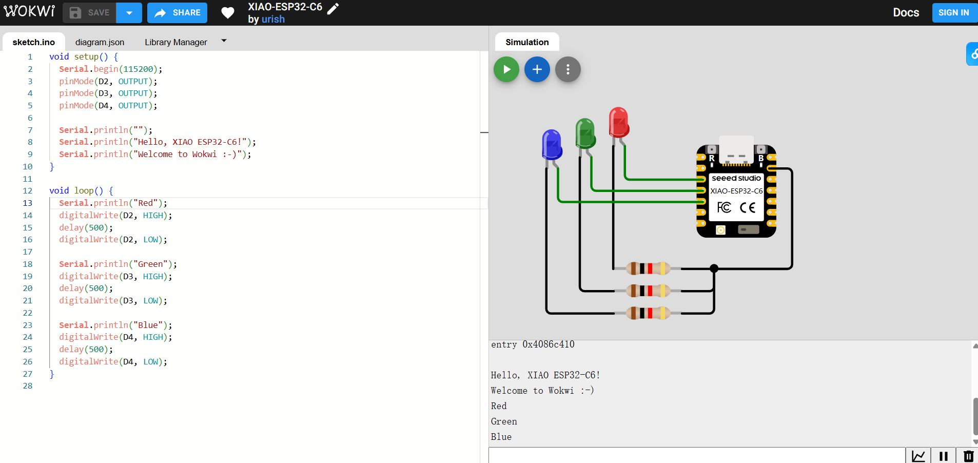
Upon opening, a default example code that cycles through three LED lights is displayed. I clicked Run to observe the simulation results. In the serial monitor below the simulation interface, debugging information was printed.
Then, I modified the setup by removing two LEDs, leaving only one red LED, and adjusted the code to make it blink every 0.5 seconds. The program executed successfully.
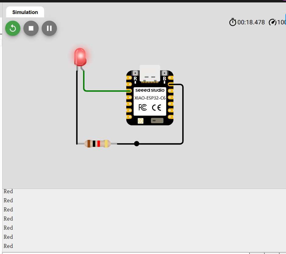
    void setup() {
        Serial.begin(115200);
        pinMode(D2, OUTPUT);
    }

    void loop() {
        Serial.println("Red");
        digitalWrite(D2, HIGH);
        delay(500);
        digitalWrite(D2, LOW);
    }
Connecting External Components
Using Wokwi to Connect XIAO-ESP32-C6 with Virtual Components
Wokwi allows us to connect XIAO-ESP32-C6 with virtual components. In the Wokwi component library, I searched for Button and connected one pin of the button to GPIO 4 and the other pin to GND.
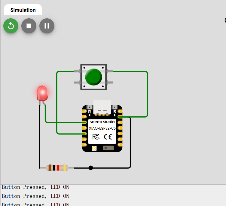
After running the simulation, pressing the button turns the LED on.
    void setup() {
        Serial.begin(115200);
        pinMode(D2, OUTPUT);
        pinMode(D4, INPUT_PULLUP);
    }

    void loop() {
        if (digitalRead(D4) == LOW) {
            digitalWrite(D2, HIGH);
            Serial.println("Button Pressed, LED ON");
        } else {
            digitalWrite(D2, LOW);
            Serial.println("Button Released, LED OFF");
        }
    }
Conclusion
Simulating XIAO-ESP32-C6 on Wokwi has several advantages:
- No need for physical hardware, making it ideal for rapid development and learning.
- Supports multiple peripherals (LEDs, buttons, OLED, Wi-Fi, etc.).
- Serial debugging functionality helps quickly locate issues.
- Supports multiple development frameworks, allowing development with ESP-IDF or Arduino frameworks.
mPython Development Board
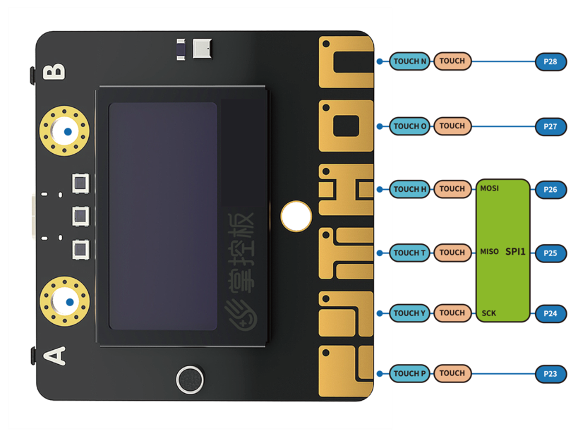
Handpy is the primary microcontroller board I use with students. It is equipped with an ESP-WROOM-32 dual-core chip, supporting WiFi and Bluetooth dual-mode communication. The board integrates a 1.3-inch OLED display, accelerometer, sound and light sensors, buzzer, 2 physical buttons, and 6 touch buttons. Additionally, it provides a resistive input interface for easy connection to various resistive sensors. Due to its compact size and multiple onboard sensors, it is very suitable for beginners to learn and develop projects.
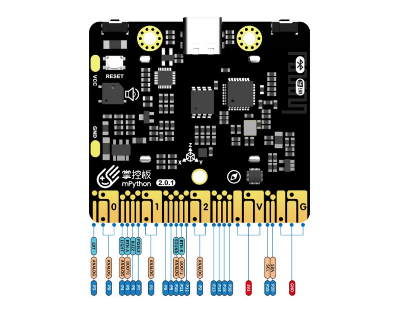
Technical Specifications
- Power Supply: USB power; external lithium battery interface power supply
- Operating Voltage: 3.3V
- Operating Current: 100mA
ESP-32 Microcontroller
- Processor: Tensilica LX6 dual-core processor
- One core handles high-speed connections
- One core for independent application development
- Clock Speed: Up to 240MHz
- SRAM: 520KB
- Flash Storage: 4MB
Wireless Communication
- Wi-Fi Standard: FCC/CE/TELEC/KCC
- Wi-Fi Protocol: 802.11 b/g/n/d/e/i/k/r (supports 802.11n, speed up to 150 Mbps), A-MPDU and A-MSDU aggregation, supports 0.4μs protection interval
- Wi-Fi Frequency Range: 2.4~2.5 GHz
- Bluetooth Protocol: Compliant with Bluetooth v4.2 BR/EDR and BLE standards
- Bluetooth Audio: Supports CVSD and SBC encoding
- Low Power Consumption Mode: 10μA
Onboard Resources
- Six-axis Sensor: QMI8658C (LGA-14) - Gyroscope (±2048°/s), Accelerometer (±16g)
- Light Sensor: ALS-PT19-315C photoresistor
- Microphone: HEM4013BTC1R16B-T0-423
- Magnetic Field Sensor: MMC5603NJ (3-axis, ±30G, precision 0.0625mG/LSB)
- Buzzer: SMD-050020F-03040N
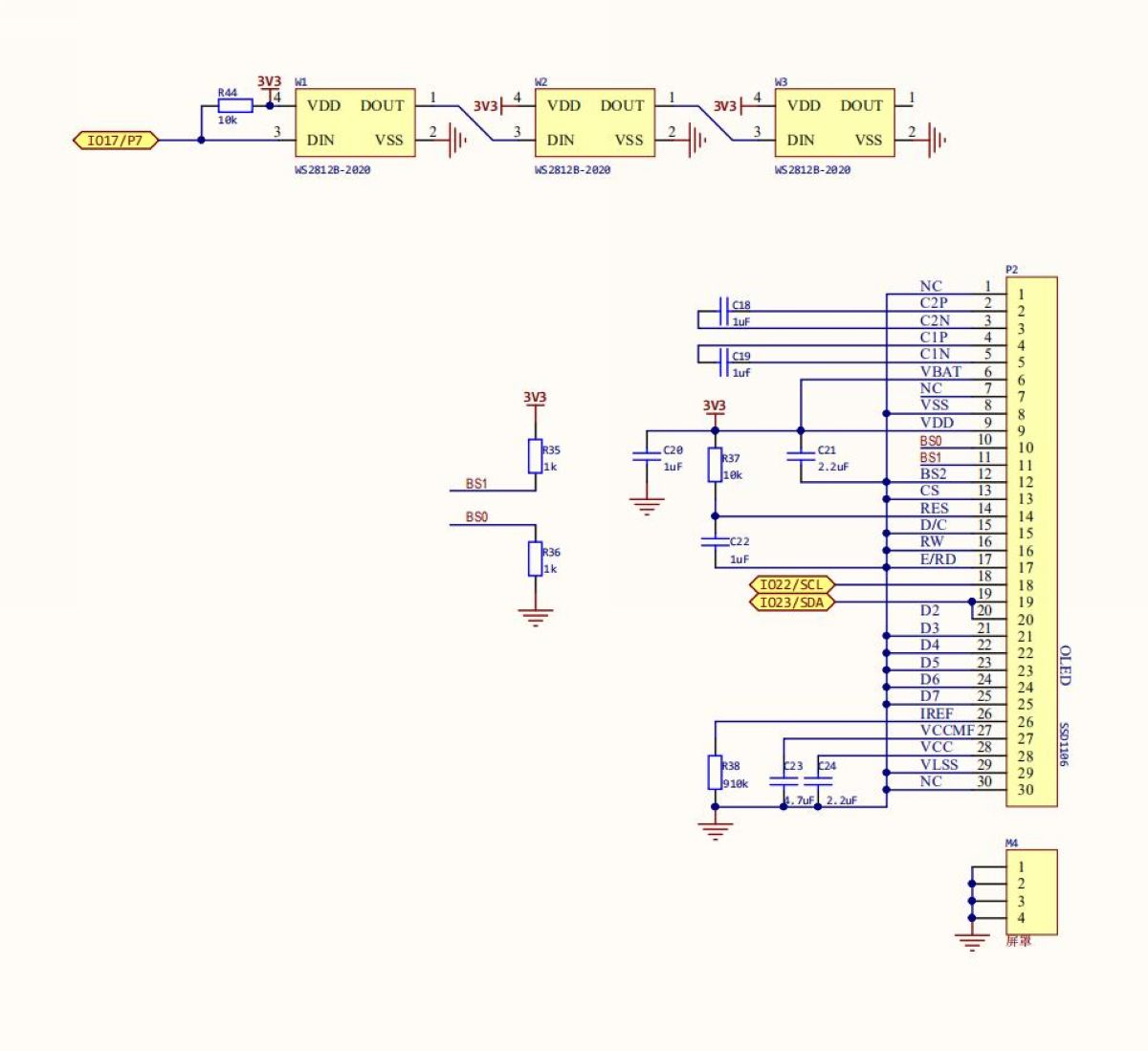
- RGB LED: 3 WS2812-2020 RGB-LEDs
- OLED Screen: 1.3-inch, 128x64 resolution, supports Chinese and English character display
- Buttons: 2 physical buttons (A/B), 6 touch-sensitive buttons
- 1 external input interface for easy connection to various resistive sensors
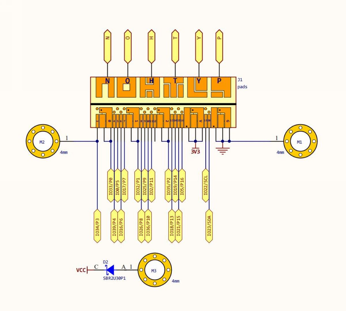
Expansion Interfaces
- 20 digital I/O channels (D0~D20) - Some shared with onboard resources, supports 2 DAC, 18 PWM, 6 touch inputs
- 5-channel 12-bit Analog Input ADC (A0~A4)
- 1 external crocodile clip input interface (EXT/A2/GND)
- I2C Interface
- UART Interface
- SPI Interface
Pin Function Description
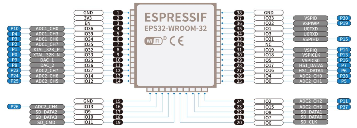
| Pin Number | Function Description |
|---|---|
| P0 | Analog/Digital Input, Analog/Digital Output |
| P1 | Analog/Digital Input, Analog/Digital Output |
| P2 | Analog/Digital Input |
| P3 | Analog Input, Connected to the Makey Board EXT Crocodile Clip, Can Connect to Resistive Sensors |
| P4 | Analog Input, Connected to the Makey Board Light Sensor |
| P5 | Digital Input, Analog/Digital Output, Connected to the Makey Board Button A |
| P6 | Digital Input, Analog/Digital Output, Connected to the Makey Board Buzzer (Can Be Used as Digital IO When Buzzer Is Not in Use) |
| P7 | Digital Input, Analog/Digital Output, Connected to the Makey Board RGB LED |
| P8 | Digital Input, Analog/Digital Output |
| P9 | Digital Input, Analog/Digital Output |
| P10 | Analog Input, Connected to the Makey Board Sound Sensor |
| P11 | Digital Input, Analog/Digital Output, Connected to the Makey Board Button B |
| P12 | Reserved |
| P13 | Digital Input, Analog/Digital Output |
| P14 | Digital Input, Analog/Digital Output |
| P15 | Digital Input, Analog/Digital Output |
| P16 | Digital Input, Analog/Digital Output |
| 3V3 | Power Input: When Connected to USB, the Makey Board Internally Regulates to Output 3.3V. When Not Connected to USB, It Can Be Powered by an Input Voltage of (2.7-3.6)V |
| P19 | Digital Input, Analog/Digital Output, I2C Bus SCL, Shared with the Internal OLED and Accelerometer |
| P20 | Digital Input, Analog/Digital Output, I2C Bus SDA, Shared with the Internal OLED and Accelerometer |
| GND | Power GND |
| Touch_P (P23) | Touch Input (TouchPad) |
| Touch_Y (P24) | Touch Input (TouchPad) |
| Touch_T (P25) | Touch Input (TouchPad) |
| Touch_H (P26) | Touch Input (TouchPad) |
| Touch_O (P27) | Touch Input (TouchPad) |
| Touch_N (P28) | Touch Input (TouchPad) |
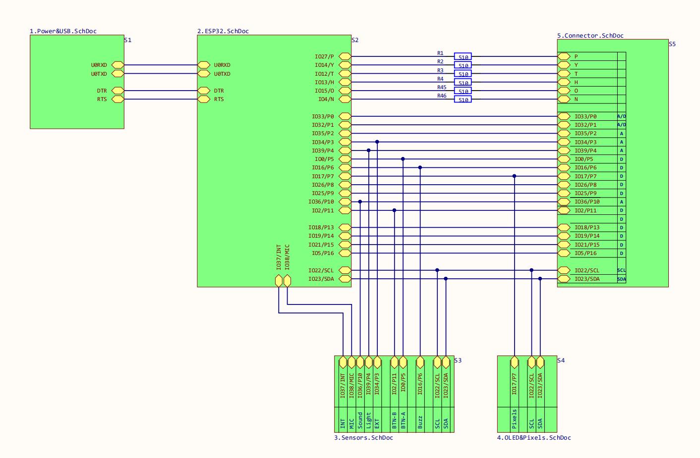
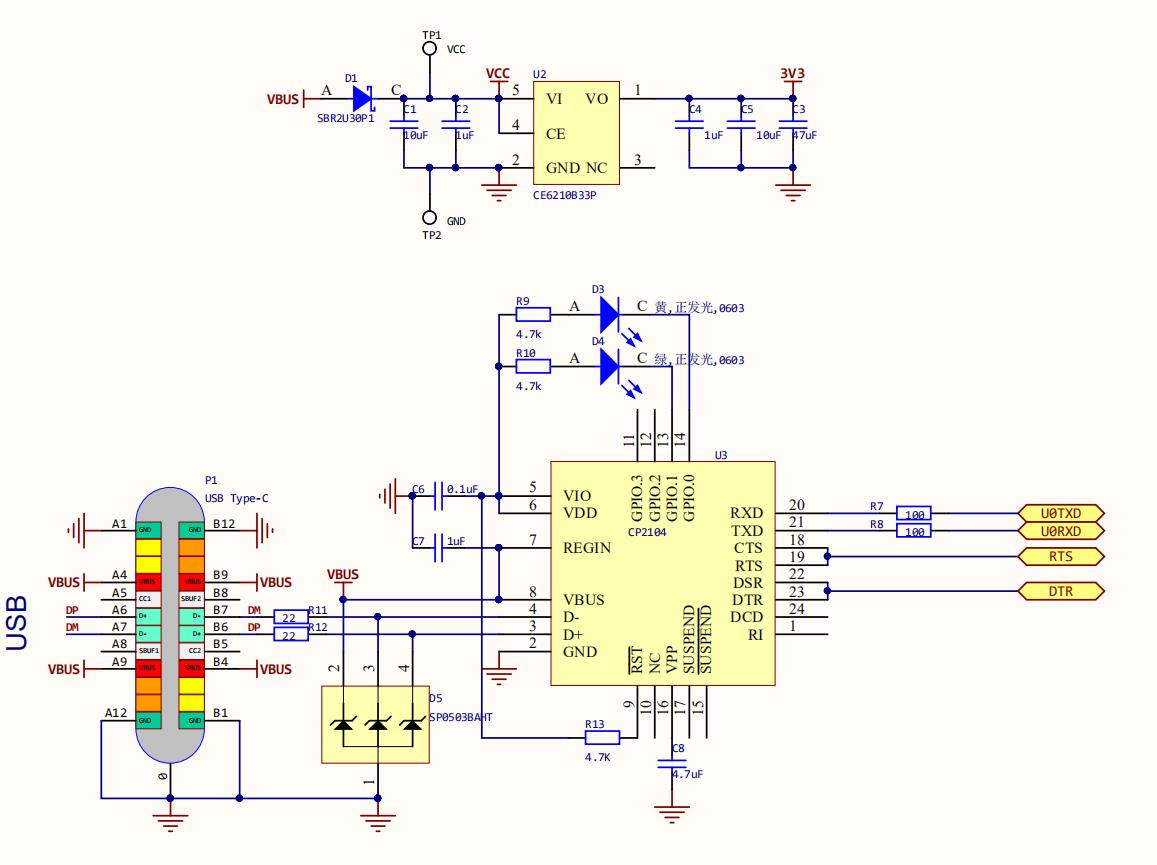
Power & USB
Sensors
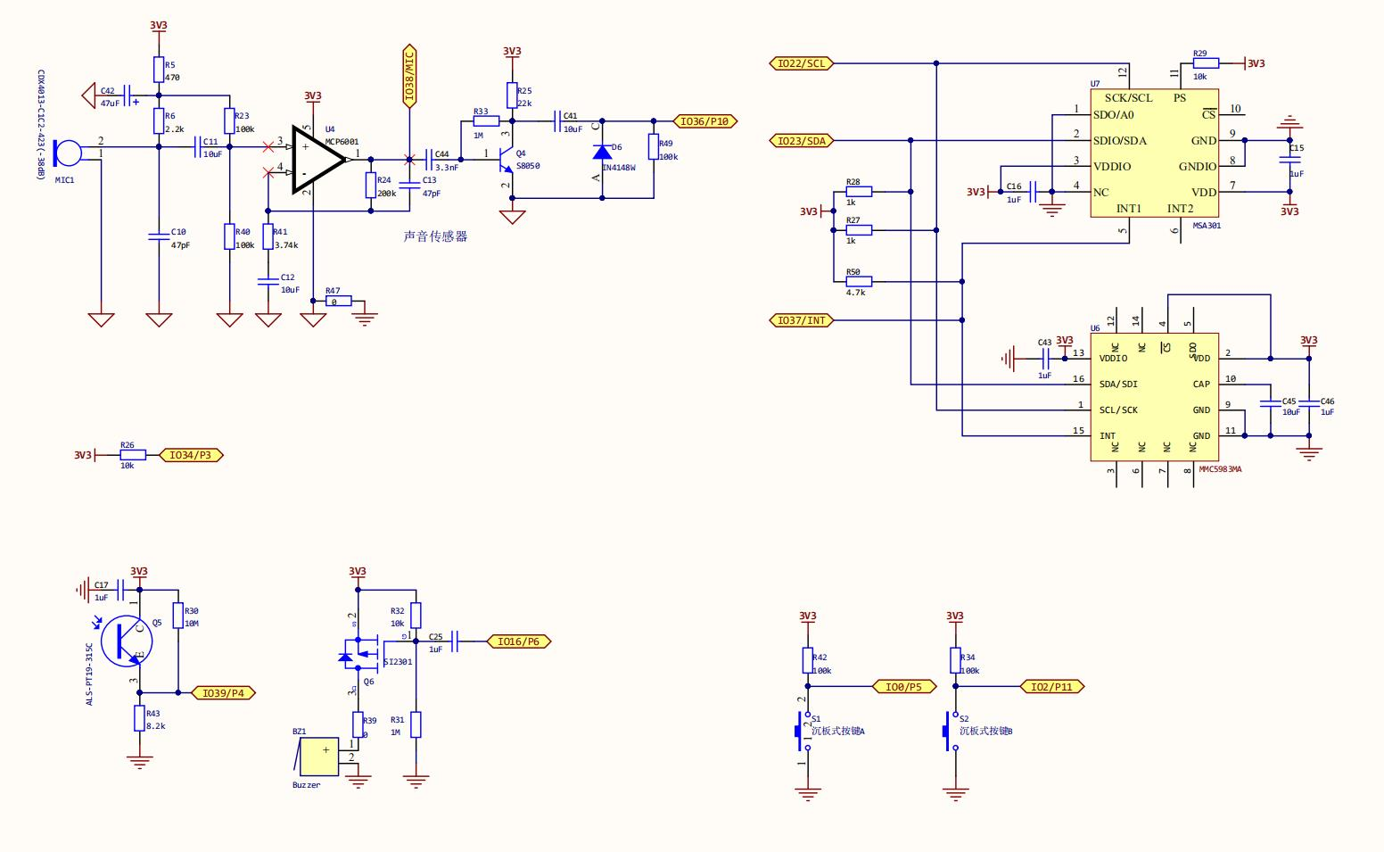
ESP32
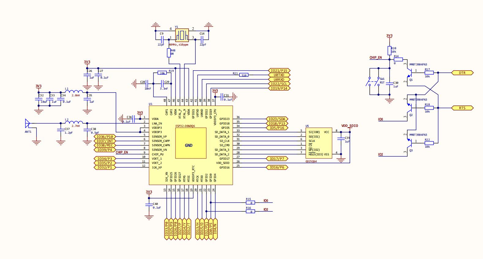
OLED and RGB
Expansion Interface
Handpy Programming
Handpy supports Arduino IDE, MicroPython, and Mind+. I have tested code execution using these two compilers.
Arduino IDE
Process:
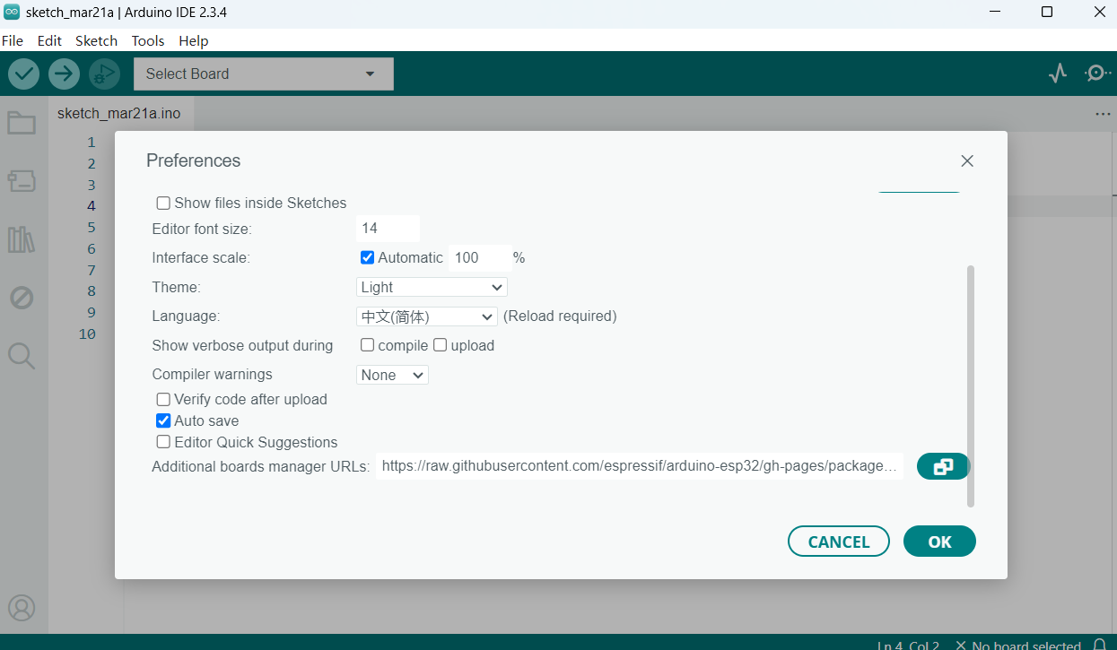
- Open the Arduino software, click on the menu: File → Preferences to open the Arduino settings interface.
- In the "Additional Boards Manager URLs" field, enter:https://raw.githubusercontent.com/espressif/arduino-esp32/gh-pages/package_esp32_index.json
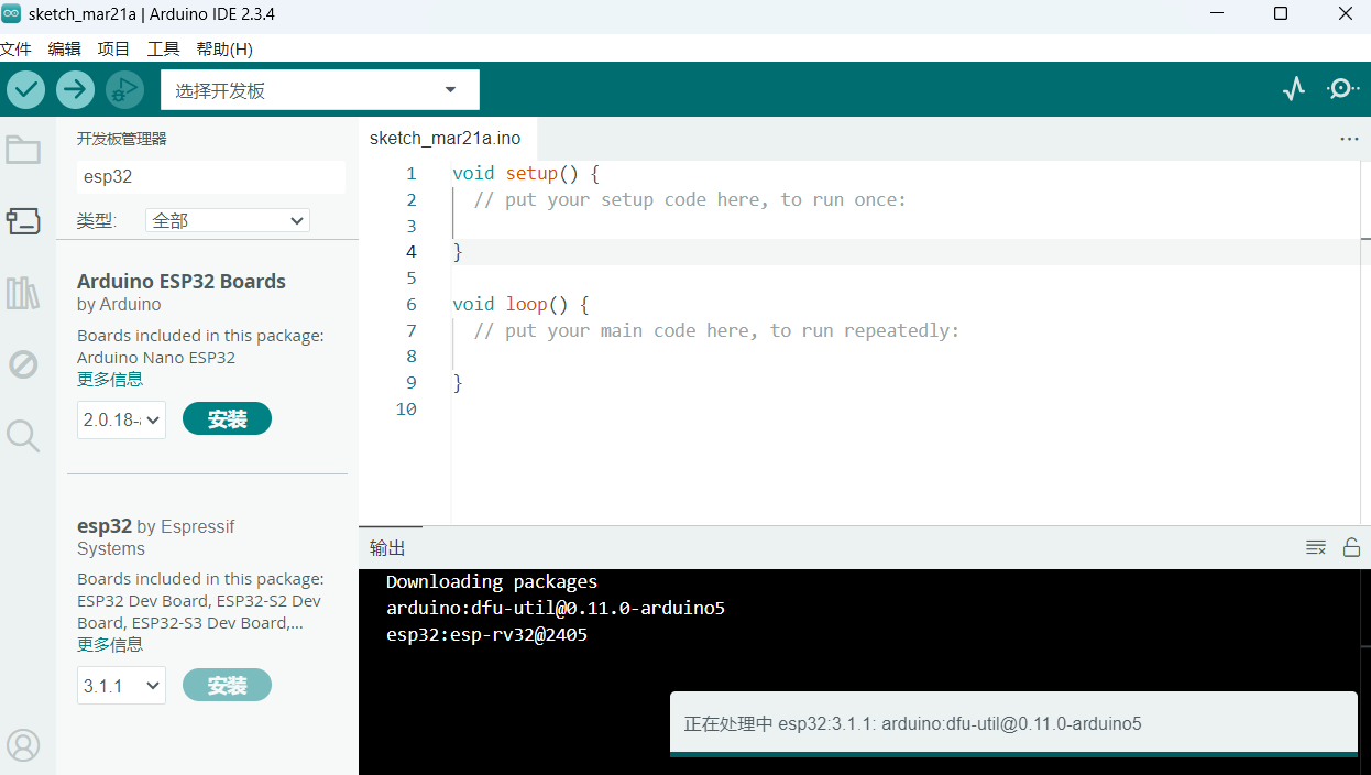
- Search for ESP32 and start downloading; however, the speed is very slow...
- I attempted to install it about 10 times but still failed, spending 3 hours in total.
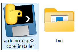
- I sought solutions in the CSDN community and found a recent post suggesting that if installing ESP32 on Arduino IDE fails, you can use the following tool (Arduino ESP32 Core Installer) for one-click installation:arduino-esp32-core-installer
- After downloading and extracting, double-click arduino_esp32_core_installer.exe in the folder to run the installer and wait patiently.
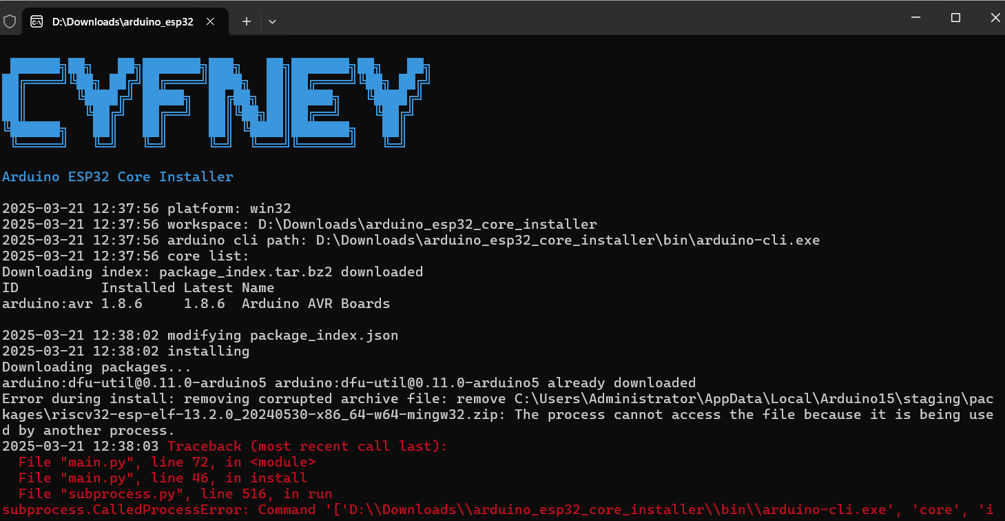
- Once complete, it will display Installation succeeded. Restart the Arduino IDE.
- Initially, I didn't close the Arduino IDE, causing the installation to fail.
- After closing and reinstalling, it took about 10 minutes, and then the required libraries were successfully installed!
- Select ESP32 Dev Module in the board options and choose the port.

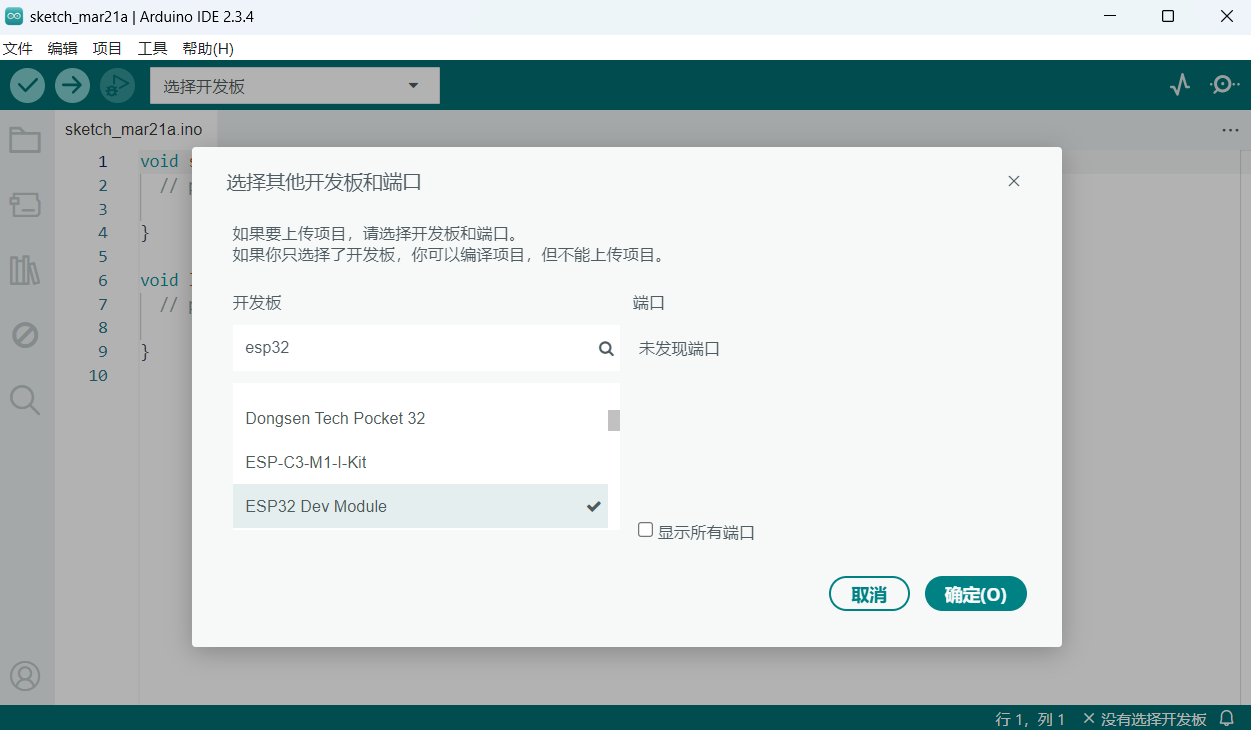
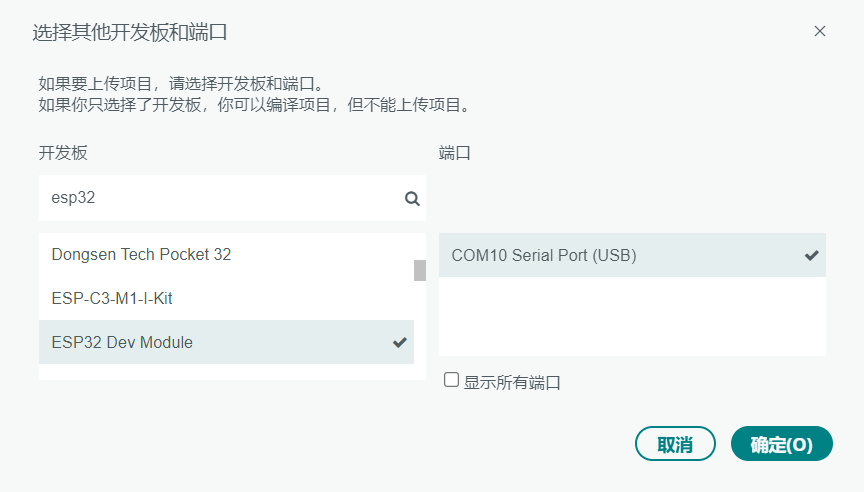
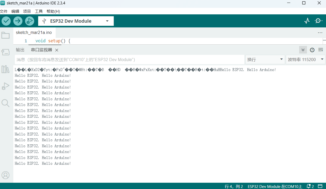
I wrote a program for serial output: Hello ESP32. Hello Arduino!
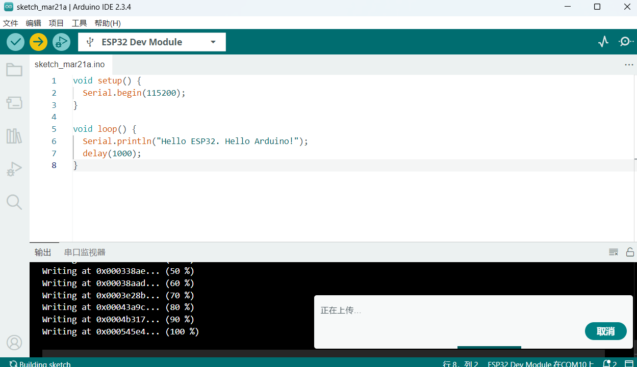
void setup() {
        Serial.begin(115200);
    }

    void loop() {
        Serial.println("Hello ESP32. Hello Arduino!");
        delay(1000);
    }
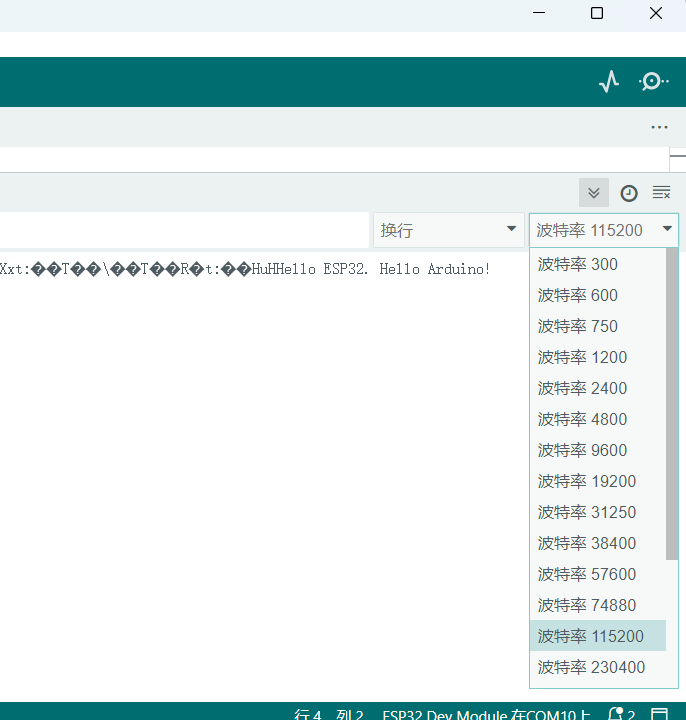
I opened the serial monitor and found the output was garbled.
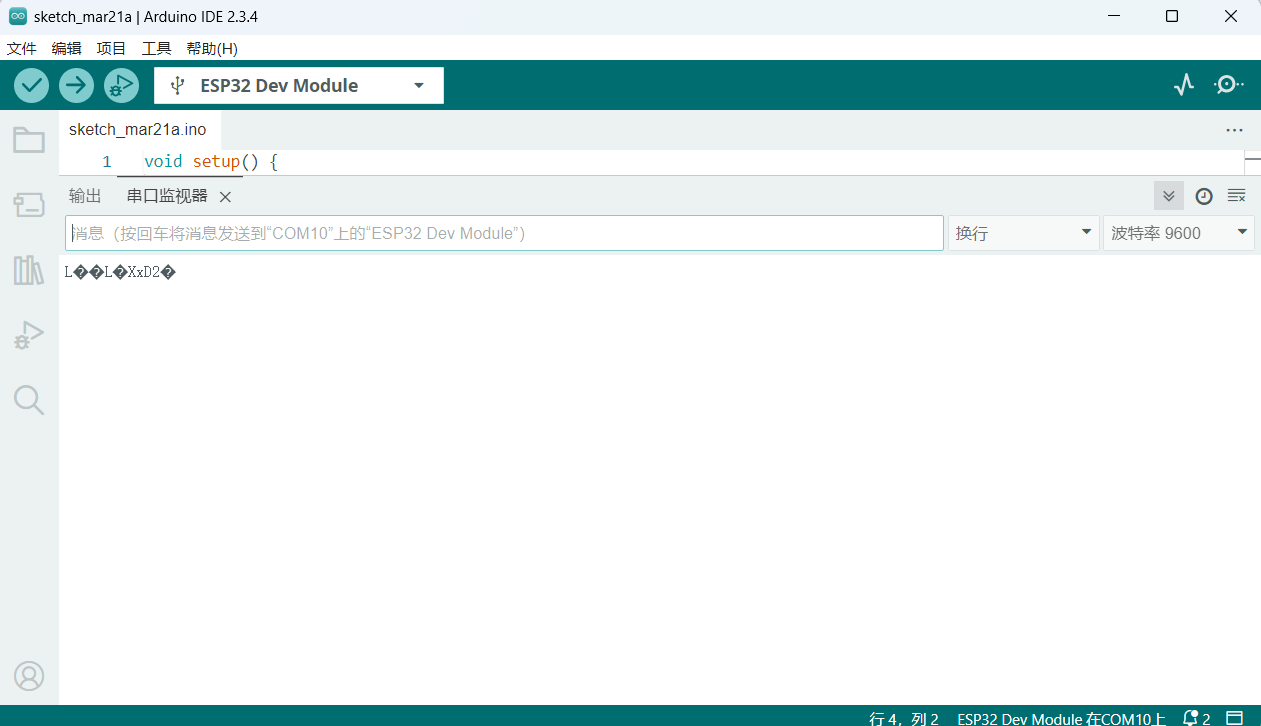
It turned out the baud rate wasn't set to 115200. After switching to the correct baud rate, the output was correct.
Mind+
I am a primary school STEAM teacher and often use simple and easy-to-operate electronic hardware and platforms. Mind+ is one of them.
Mind+ is a graphical programming platform developed by DFRobot that integrates various mainstream controllers and hundreds of open-source hardware. It supports both graphical and Python/C++ text programming modes. Download link: https://mindplus.cc
Process:
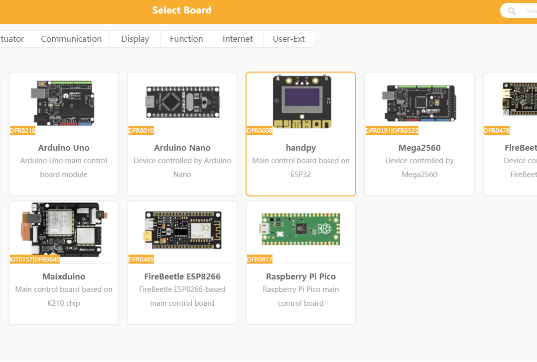
- Open the Mind+ software and add the "掌控板" (Handpy) extension in the lower-left corner.
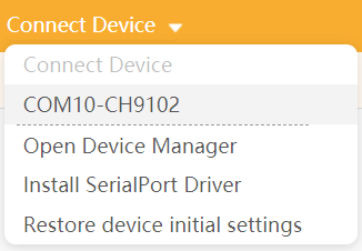
- Connect the port.
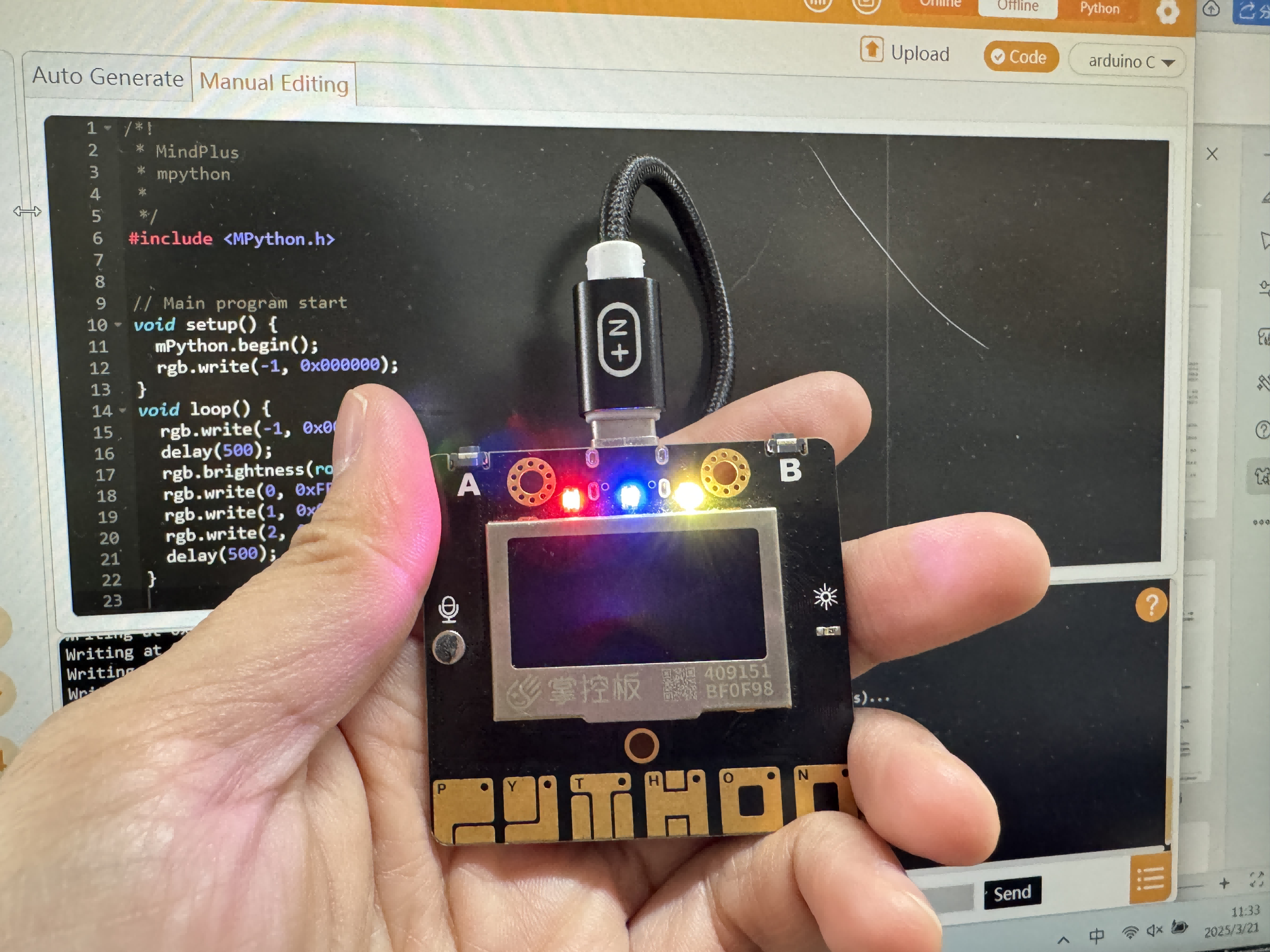
- I wrote code to control the three onboard RGB lights of the Handpy. They blink every 500ms. Light 0 is red, light 1 is blue, and light 2 is yellow. I uploaded the code to the board.
- I found the blinking was too fast, so I changed the delay to 1000ms.
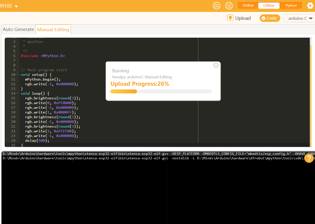
/*!
        * MindPlus
        * mpython
        */
    #include <MPython.h>

    void setup() {
        mPython.begin();
        rgb.write(-1, 0x000000);
    }

    void loop() {
        rgb.write(-1, 0x000000);
        delay(500);
        rgb.brightness(round(3));
        rgb.write(0, 0xFF0000);
        rgb.write(1, 0x0000FF);
        rgb.write(2, 0xFFFF00);
        delay(500);
    }
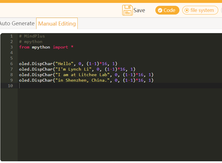
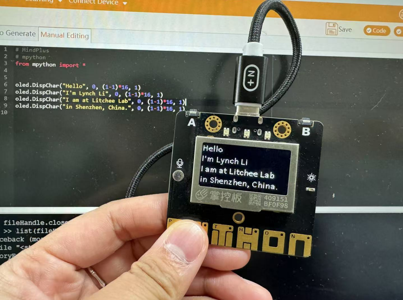
Then I used Python mode to write a greeting message on the onboard LCD screen (which can display 4 lines).
# MindPlus
    # mpython
    from mpython import *

    oled.DispChar("Hello", 0, (1-1)*16, 1)
    oled.DispChar(" I'm Lynch Li", 0, (1-1)*16, 1)
    oled.DispChar("I am at Litchee Lab", 0, (1-1)*16, 1)
    oled.DispChar("in Shenzhen, China.", 0, (1-1)*16, 1)
Reflection
During this week’s learning and practice, I focused on the topic of "Embedded Architecture Toolchains and Development Workflows." I explored and operated a variety of embedded development platforms, including ESP32, AVR, ARM Cortex-M, RISC-V, as well as simulated programming with XIAO-ESP32-C6 using Wokwi, and completed actual programming experiments with a physical microcontroller board. This week’s experience not only deepened my understanding of different embedded architectures and toolchains, but also enhanced my problem-solving and hands-on skills.
Comparing Architectures: Deepening My Understanding
Through reading documentation, organizing materials, and completing the group comparison report, I realized that different embedded architectures (e.g., ESP32, STM32, AVR, RISC-V) differ significantly in terms of toolchain configuration, programming interfaces, and development processes:
- ESP32: Strong connectivity, rich ecosystem, ideal for IoT projects.
- AVR/Arduino: Easy to get started with, suitable for education and rapid prototyping.
- ARM Cortex-M: Excellent performance in industrial and high-performance scenarios.
- RISC-V: Open-source and fast-growing, though the ecosystem is still maturing.
This comparison helped me form a more rational understanding of choosing the right tools—different projects call for different architectures and development methods.
Simulated Programming Enabled Rapid Experimentation
I used the Wokwi platform to simulate development with the XIAO-ESP32-C6. The platform provides a user-friendly graphical interface and supports serial debugging and virtual circuit connections. Through several small experiments, I accomplished:
- Removing extra LEDs and keeping only a red one, programming it to blink every 0.5 seconds;
- Adding a button and using digitalRead() to control the LED on/off;
- Observing serial output for debugging to verify logic correctness.
This showed me that even without physical hardware, I could design and validate embedded logic in a simulated environment, greatly improving development efficiency.
Hands-On Practice with Microcontroller Board: From Arduino to Mind+
I used the Handpy board (based on ESP32) and practiced in various programming environments:
1. Development with Arduino IDE
While installing the ESP32 support package in the Arduino IDE, I encountered multiple failures. After researching on CSDN forums, I downloaded the “ESP32 Core Installer” one-click installation tool and finally resolved the issue. This taught me how to face and solve real-world problems in a development environment.
2. Graphical Programming with Mind+
As an elementary school STEAM teacher, Mind+ is a visual programming tool I often use with my students. It’s beginner-friendly and allows me to teach LED control, buzzers, RGB lights, and more. In this project, I used Mind+ to control onboard RGB LEDs and fine-tuned the delay time for an improved effect.
3. Displaying Messages with Python
I also tried programming with MicroPython and displayed a greeting on the OLED screen of the Handpy board:
"Hello, I'm Lynch Li. I am at Litchee Lab in Shenzhen, China."
My Takeaways and Reflections
This week marked the first time I experienced a complete embedded development workflow, spanning document research, simulation, and physical hardware development—from selecting components, installing tools, to writing and testing code.
Facing problems such as tool installation failures, incorrect baud rate settings, and LED blinking issues, I learned to independently troubleshoot, seek out solutions, and fix bugs.
From a teaching perspective, I also became clearer on which platforms are better for beginners and which are suitable for advanced projects. This will help me guide students more effectively in future hands-on activities and competitions.