System Integration
Back to HomeGoals
assignment
- Design and document the system integration for your final project
Assignment
1. System Overview and Objective
1.1 Background & Motivation
In the natural world, many organisms possess an instinct for “approaching benefits and avoiding harm.” When a threat appears in their environment, they often respond with rapid avoidance through sensing, decision-making, and immediate action.
This project aims to simulate such biological behavior by building a quadruped robot prototype that can detect human approach direction → quickly evade → trigger light warning, through embedded system-level integration.
This is not only a technical integration exercise but also an exploration of how biologically inspired intelligent behaviors can be reproduced in robotic systems. The project integrates perceptual input (sensors), motion output (servos), emotional expression (RGB lighting), and decision-making control (microcontroller programming) to create an embedded system that can react to environmental changes and be applicable in real-world scenarios.
1.2 Project Goals & Capabilities
This system integrates multiple sensors and actuators to build a responsive robotic system with quadruped mobility, human proximity perception, and visual status feedback. Specific goals include:
- Perceptual Capability
- Two PIR infrared sensors are installed on the left and right sides of the robot to detect nearby human presence.
- The system can distinguish among three states: “approach from left,” “approach from right,” and “no approach.”
- Decision-Making Capability
- The microcontroller compares the inputs from both PIR sensors.
- It switches behavior logic accordingly (e.g., move left, move right, or stay still).
- Motion Capability
- Controls eight SG90 servos to drive quadruped movement.
- Supports basic gait control including standing, walking forward, turning left/right, and retreating.
- Expressive Capability
- Integrates a WS2812 RGB LED ring to visually represent system status:
- Normal (no threat): Blue breathing light (smooth fade in/out)
- Alert (human detected): Red fast flashing (panic/alarm signal)
- Stable Operation
- Supports both battery and USB power input.
- Runs efficiently on the microcontroller with good real-time performance and robustness.
1.3 System Behavior Flowchart
            ┌────────────────────┐
            │   System Initialization   │
            └────────────┬────────────┘
                        ↓
            ┌────────────────────────────┐
            │ Initialize Servos and RGB Ring │
            └────────────┬────────────────┘
                        ↓
            ┌────────────────────────────┐
            │  Set RGB Ring to Blue Breathing │
            └────────────┬────────────────┘
                        ↓
            ┌──────────────────────┐
            │ Read Left and Right PIR Sensors │◄────────────┐
            └────────────┬─────────┘             │
                        ↓                       │
                ┌──────────────┐   No Person Detected
                │  Evaluate Sensor Input  │─────────────┘
                └─────┬──────────┬──────┘
                        │          │
            Left Triggered   Right Triggered
                ↓                 ↓
            ┌────────────┐     ┌────────────┐
            │ Move Right │     │ Move Left  │
            └─────┬──────┘     └─────┬──────┘
                ↓                  ↓
            ┌────────────────────────────┐
            │ Switch RGB Ring to Red Flashing │
            └────────────┬──────────────────┘
                        ↓
            ┌──────────────────────────────┐
            │ Stop Movement, Return to Sensor Check │→→→→ (Loop)
            └──────────────────────────────┘
Flowchart Annotations
- System Initialization: Upon powering on, the system initializes the microcontroller, servos, PIR sensors, and the RGB LED ring.
- Blue Breathing Light: Indicates standby mode or no external disturbance.
- PIR Detection: Both left and right PIR sensors are continuously read to determine if a person is approaching.
- Behavioral Decision: If someone is detected on the left side, the robot moves right; if on the right side, it moves left. Simultaneously, the RGB LED ring switches to rapid red flashing as a warning signal.
- Loop Back: After each action, the system returns to the PIR sensor reading phase and continues monitoring the environment.
1.4 System Architecture
The overall system structure is illustrated as follows:
                    ┌────────────┐
                    │ Left PIR Sensor │
                    └──────┬──────┘
                            ↓
                    ┌──────────────────────┐
                    │ XIAO ESP32S3 Microcontroller │
                    └────┬────┬────┬────────────┘
                        │    │    │
                ┌──────┘    │    └──────────────┐
                ↓           ↓                   ↓
            Right PIR     Servo Control      RGB LED Ring (WS2812)
            (Digital In)  (PWM D1~D8)         (Data Out D10)
1.5 Behavior Flow
- Initial State:
- All servos are initialized to default angles.
- The RGB LED ring displays a blue breathing light effect.
- The system continuously reads the status of left and right PIR sensors.
- Human Detection:
- If a person is detected on the left side:
- The servos execute a “turn right and move” action.
- The RGB LED ring switches to rapid red flashing.
- If a person is detected on the right side:
- The servos execute a “turn left and move” action.
- The RGB LED ring switches to rapid red flashing.
- If no person is detected:
- The servos remain stationary.
- The RGB LED ring remains in blue breathing light mode.
- If a person is detected on the left side:
- Real-Time Response:
- Sensor status is updated every 100 milliseconds.
- Behavior and visual feedback are dynamically controlled to form a complete feedback loop.
1.6 Highlight Features
| Project Highlight | Description |
|---|---|
| Biological Behavior Simulation | Simulates animal-like logic of "threat perception → escape", enabling autonomous reactive behavior. |
| Multi-Module Integration | Integrates PIR sensors, SG90 servos, RGB LED ring, and microcontroller into a tightly coordinated system. |
| Dynamic Visual Expression | Uses RGB lighting effects to express “calm vs alert” states, enhancing human-robot interaction. |
| Expandable Structure | Allows easy replacement or upgrade to other sensors like cameras or ultrasonic modules for extended perception. |
2. Detailed Hardware Description
This system is based on the XIAO ESP32S3 development board and integrates multiple input/output modules to detect human proximity and trigger corresponding robot movements. Each module has a clear function and collaborates in real time to form a complete interactive smart system. The main hardware components are described in detail below:
2.1 Main Control Unit: XIAO ESP32S3 (Camera Version)
- Function: Core controller that processes sensor inputs, controls servos and RGB lighting.
- Advantages:
- Powered by ESP32-S3 chip, supports Wi-Fi & BLE for future remote applications.
- Compact size with rich GPIO, ideal for embedded quadruped design.
- Supports multitasking: concurrent servo and LED control.
- Pin Configuration (actual use):
- D1 (GPIO2): Left PIR sensor
- D2 (GPIO3): Right PIR sensor
- D3-D10: PWM control for 8 servos
- D11 (GPIO9): RGB LED ring data line
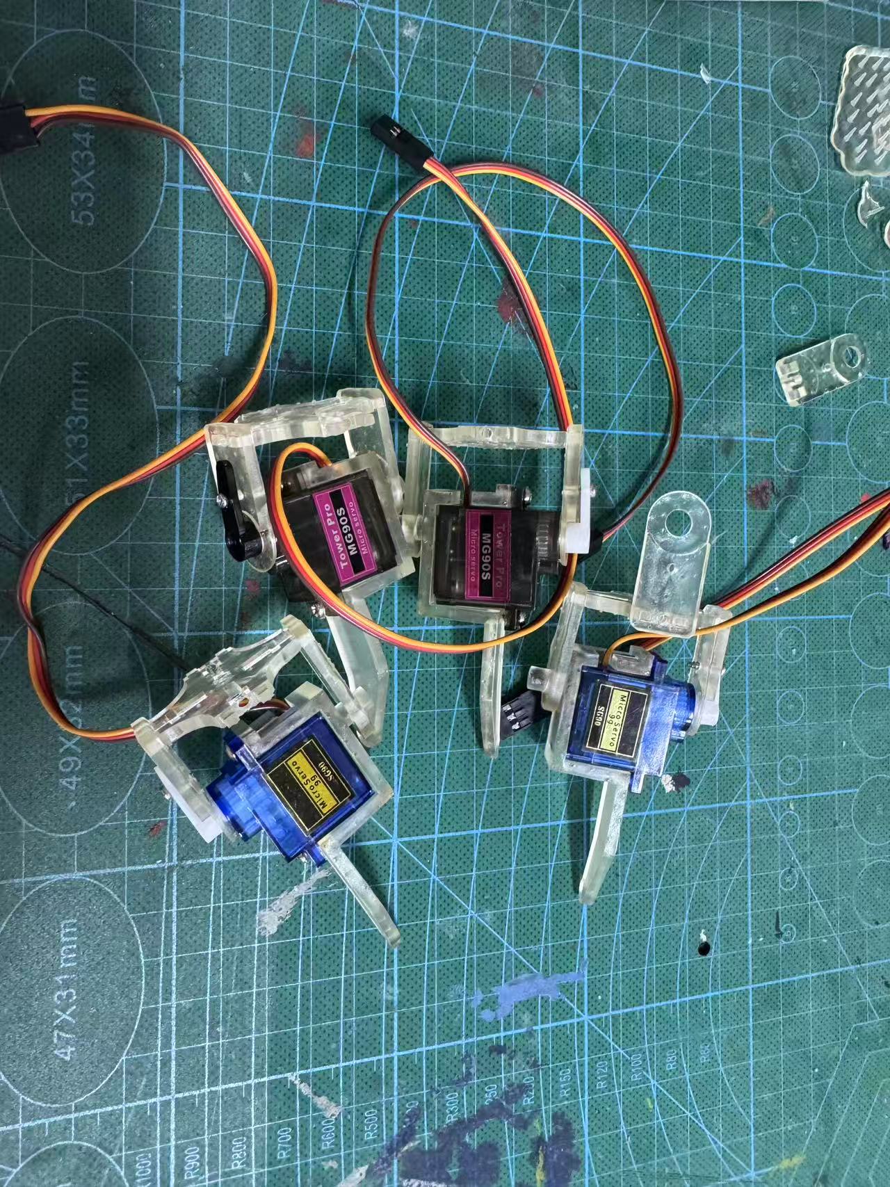
2.2 Servo Drive System: 8 × SG90 Servos
- Function: Controls leg swing and lift to enable left/right evasive movement.
- Configuration: Each leg uses 2 servos (hip + knee), total 8 servos.
- Power Supply: External 5V battery pack for high current, independent from main board.
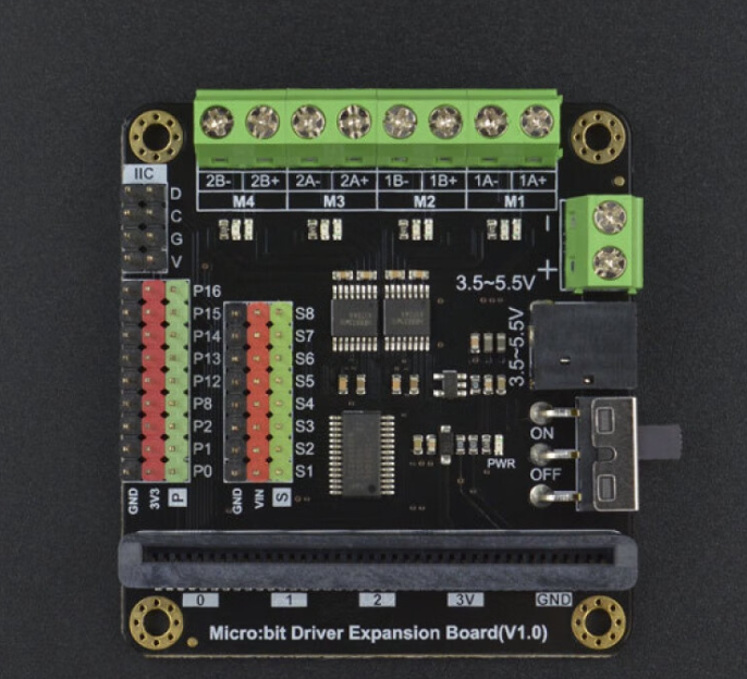
- Control Pins: S1–S8 → GPIO10–GPIO17
2.3 PIR Sensor Modules: 2 × Passive Infrared Sensors
- Function: Detect human presence from left and right directions.
- Pin Description:
- VCC → 3.3V
- GND → Ground
- OUT → Digital High = Detection
- Connection:
- Left PIR → GPIO2 (XIAO D1)
- Right PIR → GPIO3 (XIAO D2)
- Installation: Mounted at ~45° angle on both sides for wider detection coverage.
2.4 RGB LED Ring Module: WS2812
- Spec: 8 RGB LEDs in circular form.
- Function:
- Blue breathing light when idle
- Red fast flashing when human detected
- Pin Description:
- DIN → GPIO9
- VCC → 5V
- GND → Ground
- Control: Using Adafruit_NeoPixel library, supports high brightness and visual effects.
2.5 Power Management
- Main Board Power:
- USB-C during debugging
- 5V lithium battery for mobile use
- Servo Power: Independent 5V battery (>2A current capacity)
- Important: Ensure common ground between servo and controller. Double-check voltage compatibility.
2.6 Expansion Connector Board (Custom + Breadboard)
- Purpose:
- Centralized servo power and signal routing
- Dedicated ports for RGB and PIR connections
- Convenient wiring and testing
- Structure Suggestion:
- Install expansion board at robot chassis center
- Separate layers for power and signal to avoid interference
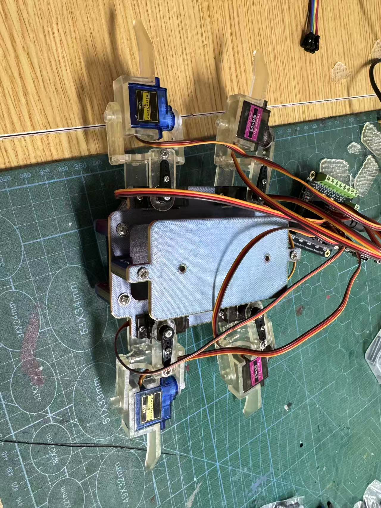
2.7 Mechanical Structure & Mounting
- Robot Body: Built with 3D-printed parts
- Leg Joints: Secured with M3 screws and nuts
- PIR Installation: Extended rear brackets for sensor mounting
- RGB Ring Placement: Inside head cavity below top cover
2.8 Tools and Equipment
- Multimeter
- Soldering iron + solder
- Hot glue gun, cable ties
- USB data cable
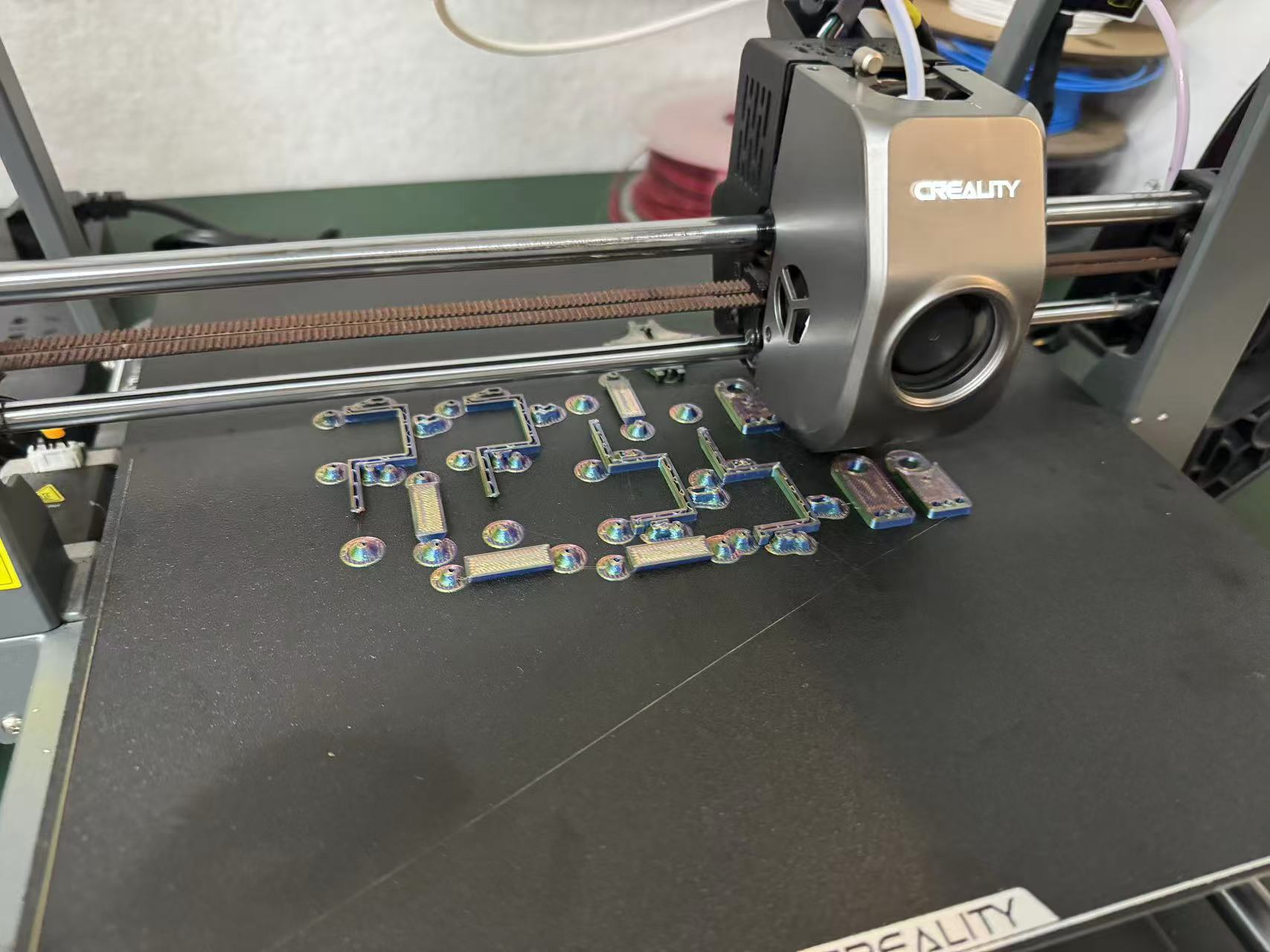
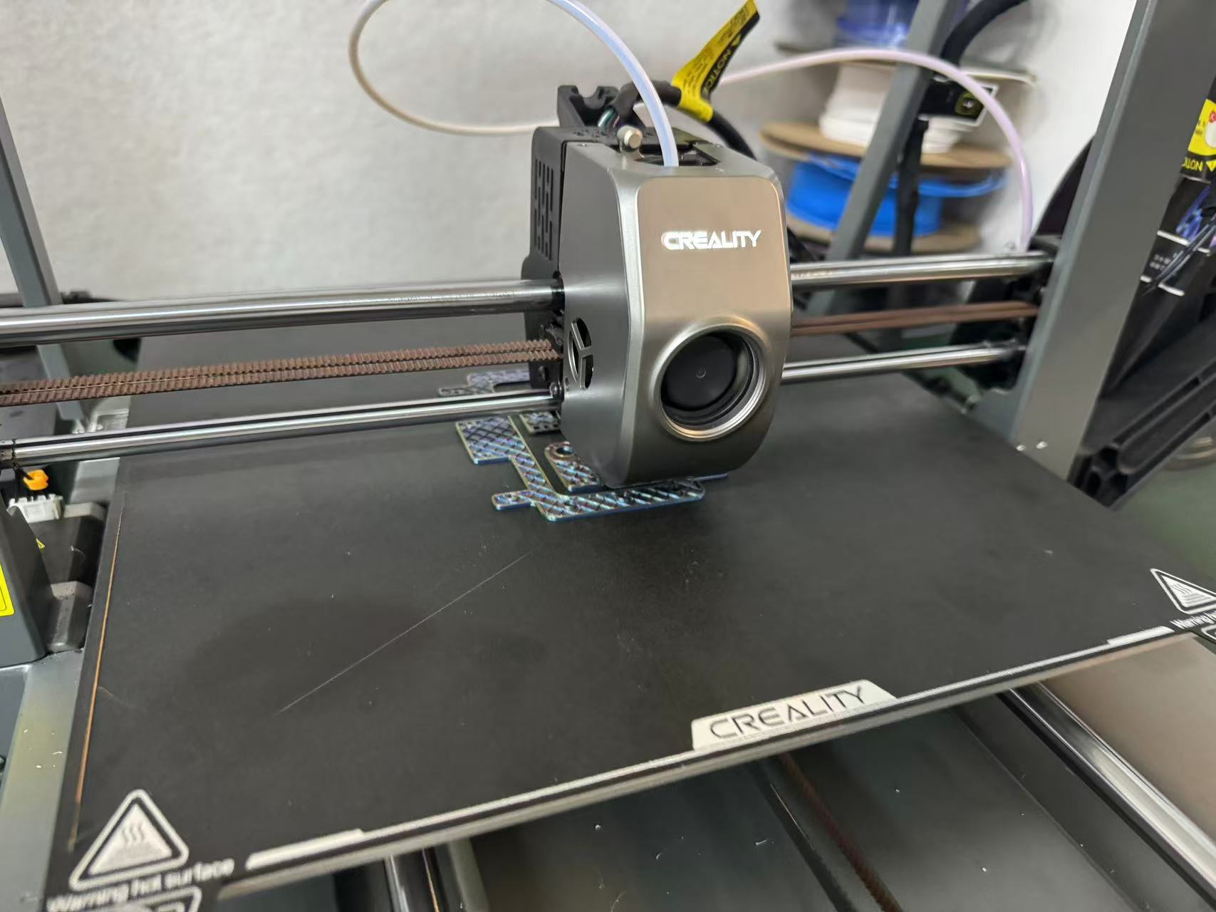
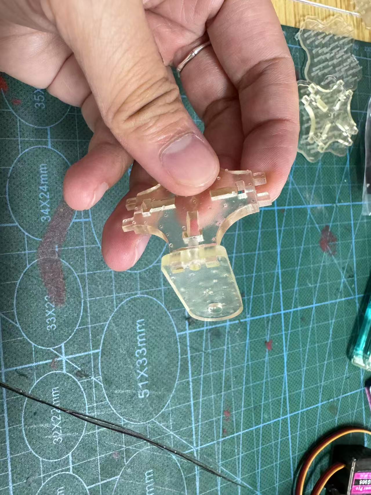
However, during assembly testing, I encountered a serious issue: the dimensional tolerance of the FDM prints was too large, especially the servo mounting holes. The connection plates for the claws could either not fit at all or were too loose in the horizontal and vertical directions.
I tried the following adjustments:
- Modified hole dimensions in the model
- Reduced print speed to improve accuracy
- Switched to a finer nozzle
Despite these attempts, the print precision still failed to meet the requirements of the mechanical structure.
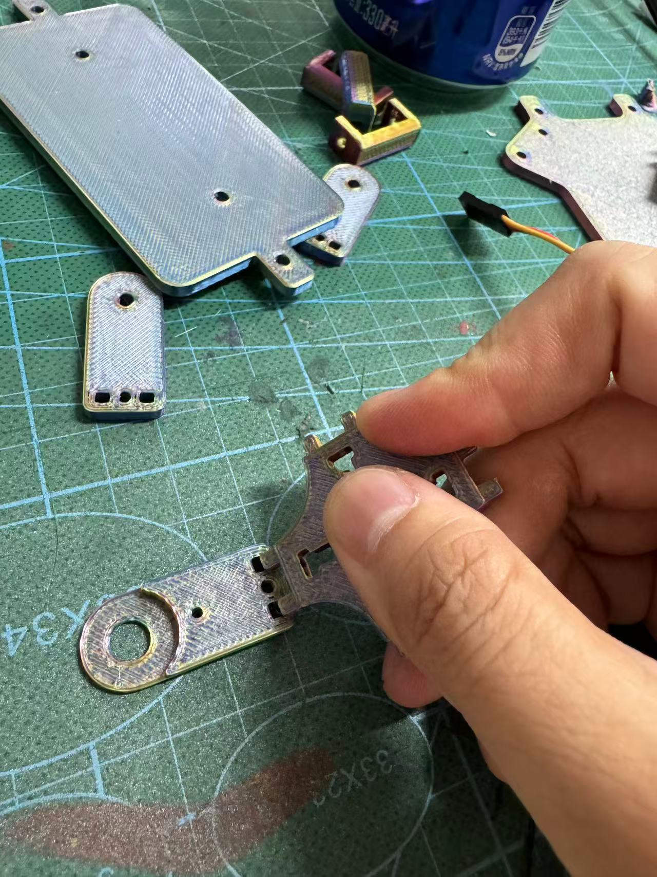
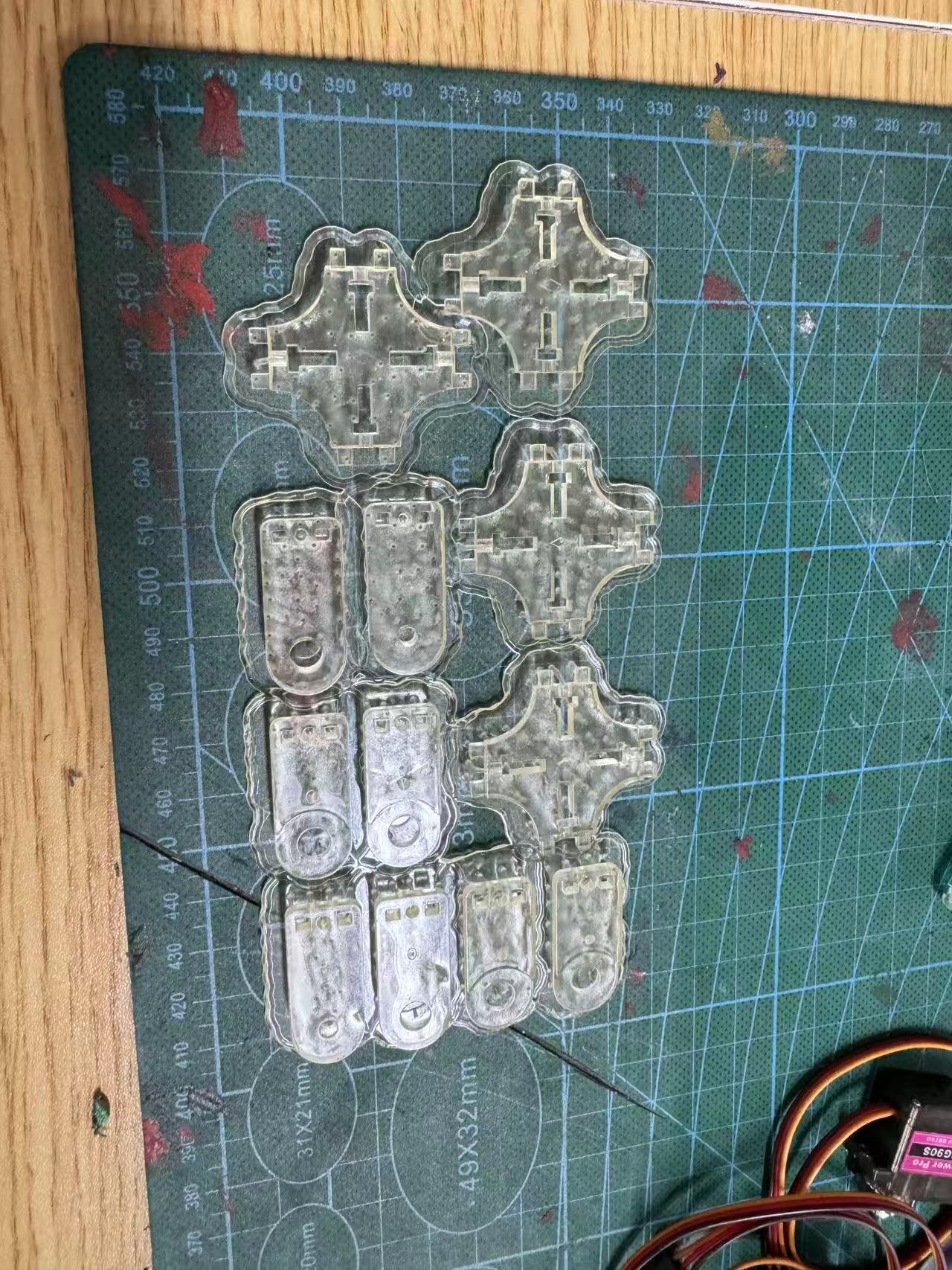
2. Precision Parts Switched to SLA Printing
Eventually, I switched all mechanical claw components—i.e., parts requiring high-precision fit with servos—to SLA resin printing. Details are as follows:
- Used an LCD-type SLA printer
- Material: standard gray photopolymer resin
- Layer height: 0.05 mm
- Print time: about 6 hours
- Post-processing: cleaned with IPA, then UV-cured
The results were very satisfying: extremely high print accuracy, perfect snap-fit, smooth surface with no layer lines, and tight, seamless assembly.
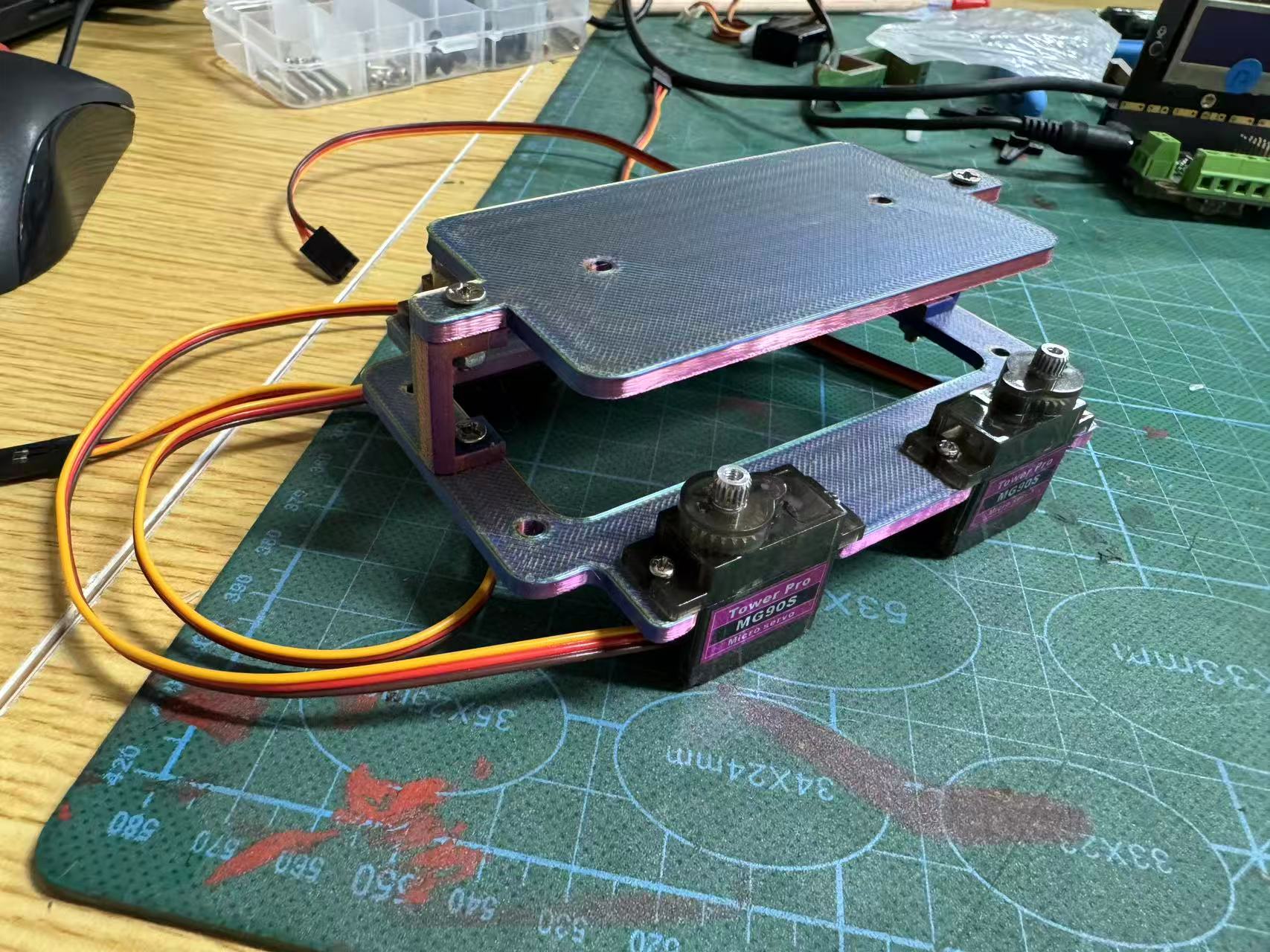
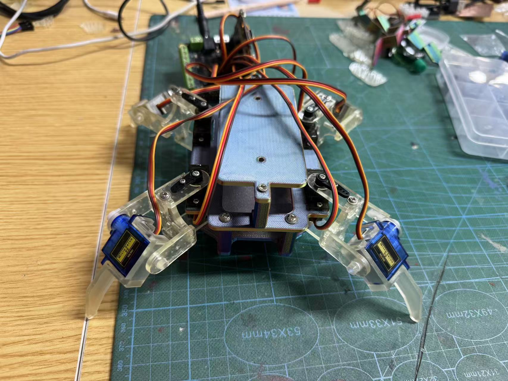
3. Central Structure and Leg Assembly
I completed the assembly of all parts and ensured the following:
- Each servo could be mounted easily and rotate within the required angle range
- Servo cables could be routed cleanly without affecting movement
- All four legs could stand stably in the initial pose, with a centered center of gravity
Part 2: Automation and Application
1. Control System Architecture Selection
After completing the structural assembly and standing stability test, I moved on to the second phase of the quadruped robot project: making the structure move and implementing basic motion logic through automated control.
1.1. Control Platform Selection and Rationale
For this phase, I chose the following setup:
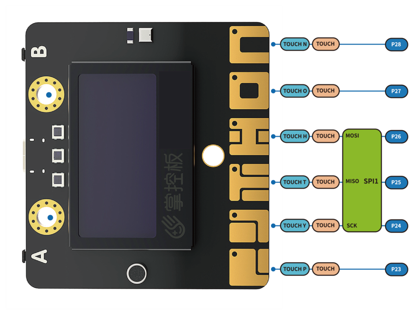
- Main controller: Handpy board
- Expansion board: DFRobot motor expansion board (based on PCA9685 chip)
- Servos: 8 x SG90
- Programming environment: Mind+ (Arduino mode, with
Microbit_Motor1control library support)

Reasons for selection:
- The Handpy board is widely used in education and comes with built-in Wi-Fi, making it convenient for future remote control applications.
- The DFRobot motor expansion board requires no manual I2C configuration—plug-and-play functionality.
- The Microbit_Motor1 library provides a simplified
servo(Sn, angle)command for servo control, making the logic easier to implement. - Mind+ supports both graphical and C++ dual-mode programming, which helps with program debugging and structured code management.
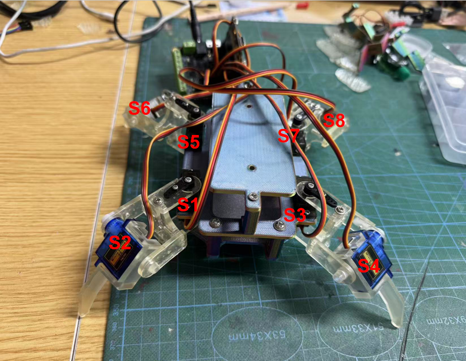
2. Servo Numbering and Body Mapping
The servo numbering scheme was defined during the structural design phase. The details are as follows (referencing the top-down structural diagram):
| Servo ID | Controlled Part | Function |
|---|---|---|
| S1 | Left front knee | Leg lift |
| S2 | Left front hip | Forward swing |
| S3 | Right front knee | Leg lift |
| S4 | Right front hip | Forward swing |
| S5 | Left rear knee | Leg lift |
| S6 | Left rear hip | Forward swing |
| S7 | Right rear knee | Leg lift |
| S8 | Right rear hip | Forward swing |
I adopted a layout in which even-numbered servos control knee joints (vertical lift) and odd-numbered servos control hip joints (horizontal swing). This mapping makes it easier to organize and program motion sequences.
3. Motion Logic Design Process
1. Initial Program Structure
I began by creating the following function structure:
DF_Initial_state(): Set all servos to 90° neutral positionDF_Standing(): Set legs into a crouched standing pose (preparation for gait)DF_Lying_down(): Simulate a lying/squatting postureDF_Move_forward_action_X(): Define four-frame forward walking sequence: A ~ D
These motion functions control each servo individually using esp.servo(Sn, angle).
2. Basic Gait Unit Design
Referring to diagonal gait patterns in real quadrupeds, I defined a full cycle as:
A → B → C → D → (loop)
| Frame | Core Motion Description |
|---|---|
| A | Lift left front + right rear leg → swing |
| B | Legs land and push forward |
| C | Lift right front + left rear leg → swing |
| D | Legs land and complete forward propulsion |
4. Code Implementation & Function Breakdown
1. DF_Initial_state(): Servo Initialization
void DF_Initial_state() {
        esp.servo(S1, 90); // Left front knee
        esp.servo(S2, 90); // Left front hip
        esp.servo(S3, 90); // Right front knee
        esp.servo(S4, 90); // Right front hip
        esp.servo(S5, 90); // Left rear knee
        esp.servo(S6, 90); // Left rear hip
        esp.servo(S7, 90); // Right rear knee
        esp.servo(S8, 90); // Right rear hip
        }
Used for zeroing servo positions after power-on to avoid erratic behavior or self-triggering.
2. DF_Standing(): Ready Posture
esp.servo(S1, 135);
        esp.servo(S2, 135);
        esp.servo(S3, 45);
        esp.servo(S4, 45);
Forms a balanced, crouched stance for starting the next leg movement.
3. DF_Lying_down(): Crouch Simulation
esp.servo(S1, 90);
        esp.servo(S2, 135);
Used to demonstrate controlled resting action and test servo angle limits.
4. Gait Core Motion Frames
[A] Lift left front + right rear → swing
esp.servo(S1, 105);
        esp.servo(S2, 165);
        esp.servo(S7, 15);
        esp.servo(S8, 165);
[B] Legs land → push forward
esp.servo(S1, 135);
        esp.servo(S2, 105);
        esp.servo(S7, 45);
        esp.servo(S8, 105);
[C] Lift right front + left rear → swing
esp.servo(S3, 15);
        esp.servo(S4, 15);
        esp.servo(S5, 105);
        esp.servo(S6, 15);
[D] Legs land → push forward
esp.servo(S3, 45);
        esp.servo(S4, 45);
        esp.servo(S5, 135);
        esp.servo(S6, 75);
5. Main Function Execution Flow
void setup() {
            DF_Initial_state();
            delay(2000);
            DF_Standing();
            delay(300);
            DF_Lying_down();
            delay(300);
            DF_Standing();
            delay(300);
            for (int index = 0; index < 5; index++) {
                DF_Move_forward_action_A();
                delay(300);
                DF_Move_forward_action_B();
                delay(300);
                DF_Move_forward_action_C();
                delay(300);
                DF_Move_forward_action_D();
                delay(300);
            }
        }
Execution logic:
Initialize → Stand → Lie down → Stand again → Perform 5 full gait cycles → Stop
This sequence demonstrates the robot's full functional flow from power-on to movement, useful for both testing and presentation.
6. Debugging and Troubleshooting
After completing the program logic design and structural assembly, I conducted multiple rounds of debugging. The main goals were:
- Ensure each servo performs as expected
- Enable stable execution of basic gaits
- Ensure system runs without overheating, jitter, or misalignment
I recorded and resolved multiple real issues through a layered diagnosis approach:
1. Unresponsive Servos or Angle Errors
Symptoms: S7 and S8 showed no movement during Action A.
Troubleshooting:
- Servos tested OK via channel swap
- Loose connector found
- No PWM output detected on D7
Solutions: Changed slot, reconnected firmly, labeled channels
2. Unbalanced Movement, Tilting or Skewed Trajectory
Symptoms: Robot leaned forward and deviated to the left
Troubleshooting:
- S1/S3 angle mismatch
- Loose servo bracket on left front leg
- S2 too far forward (165°), causing imbalance
Solutions: Symmetrical angle table, replaced parts with SLA, reinforced servo mounting
3. Overheating and Buzzing Servos
Symptoms: S2/S8 heated up and buzzed after 2 minutes
Troubleshooting:
- Long duration holding under load
- No angle overflow
- New servos showed same problem
Solutions: Limit angles, add buffer frames, use MG90S in future, extend delay()
4. Jerky or Irregular Movements
Symptoms: Frames switched before motion completion
Troubleshooting:
- Delay(300) insufficient for some moves
- Large angle jumps observed (e.g., 45° → 135°)
Solutions: Increased delay to 350ms, added intermediate angles, suggest using millis()
5. Glitchy or Unstable Control Logic
Symptoms: Random desynchronization or jitter, restored after reboot
Troubleshooting:
- Voltage drop from 5V to 4.3V under load
- Shared power line between board and servos
Solutions: Separate power supplies, added 1000uF capacitor, recommend independent DC supply
Debugging Summary
I developed a reliable debugging workflow:
- Classify problem types based on symptoms
- Diagnose layer-by-layer: software → angles → mechanics → power
- Maintain logs of servo behaviors, angles, and timing
- Record fixes for repeatability and future improvement
Ultimately, I realized that a stable robotic motion system is built on precise mechanics, reliable power delivery, and synchronized timing—not just correct code.
Quadruped_SG90_Robot_stl.rar