Networking and Communications
Back to HomeGoals
group assignment
- send a message between two projects
Individual Assignment
- design, build, and connect wired or wireless node(s) with network or bus addresses and local input &/or output device(s)
Individual Assignment
1. Assignment Objective
The objective of this assignment is to:
- Design and build a basic communication network system consisting of two nodes;
- Each node is a XIAO ESP32S3 microcontroller;
- They communicate with each other via wired UART serial communication;
- On the receiving node, a received message will trigger a response by lighting up an LED;
- Each node should be recognized as an independent device (logical address) by the program;
- The local output device is: LED module.
2. Brief Introduction to Communication Principle
I chose UART (Universal Asynchronous Receiver/Transmitter) as the communication method. It has the following characteristics:
- It is one of the most basic serial communication protocols;
- Usually requires only 3 wires: TX (transmit), RX (receive), and GND (ground);
- On the XIAO ESP32S3, I used
Serial1to implement UART communication; - The sender periodically transmits strings, and the receiver reads them to trigger LED actions.
What is UART Communication?
UART (Universal Asynchronous Receiver/Transmitter) is a serial communication protocol used to asynchronously transmit data between two devices using just a few pins (typically two wires).
It is commonly used for:
- Communication between microcontrollers (e.g., two XIAO ESP32S3 boards)
- Serial debugging between microcontroller and computer
- Communication with modules like Bluetooth, GPS, or GSM
Basic Features of UART
| Feature | Description |
|---|---|
| Asynchronous | Does not rely on a clock line (unlike SPI/I2C) |
| Point-to-point | Typically connects only two devices: one sender, one receiver |
| Full duplex | Supports simultaneous send and receive via TX and RX |
| Low cost/complexity | Only requires TX, RX, and GND lines |
| Hardware or software | Usually built into MCU, but can be implemented via software too |
UART Pins
| Name | Function |
|---|---|
| TX | Transmit data (output pin) |
| RX | Receive data (input pin) |
| GND | Ground (common ground is essential) |
Note: Connect TX to RX and RX to TX between devices. GND must also be connected.
UART Data Frame Format
UART sends data in a frame structure:
Start bit | Data bits (usually 8) | Optional parity bit | Stop bit
Example: Standard UART frame (8N1)
| Type | Length | Description |
|---|---|---|
| Start bit | 1 bit | Always LOW (0), signals start of frame |
| Data bits | 8 bits | Actual data (e.g., ASCII character) |
| Parity bit | 0 bit | None in this case (N = None) |
| Stop bit | 1 bit | HIGH (1), signals end of frame |
“8N1” = 8 data bits, No parity, 1 stop bit.
UART Communication Parameters
| Parameter | Example | Description |
|---|---|---|
| Baud rate | 9600, 115200 | Bits per second (bps) |
| Data bits | 8 | Data bits per frame |
| Stop bits | 1 | Indicates end of frame |
| Parity | None | Error check (often set to None) |
Example in Arduino:
Serial1.begin(9600, SERIAL_8N1, RX, TX);Common UART Use Cases
- Microcontroller-to-PC debugging via Serial Monitor
- Bluetooth, GPS, GSM module communication
- Control systems with multiple devices (as in your project)
- RS232 / USB-to-Serial converter cables
Comparison: UART vs Other Protocols
| Protocol | Wire Count | Mode | Speed | Device Count | Features |
|---|---|---|---|---|---|
| UART | 2 (TX + RX) | Point-to-point | Medium | 2 | Simple, asynchronous |
| I2C | 2 (SCL + SDA) | Master-slave | Medium | Multiple (via address) | Synchronous, addressable |
| SPI | ≥4 (MISO/MOSI/SCK/SS) | Master-slave | High | Multiple | Fast, but more pins needed |
| ESP-NOW | Wireless | Multipoint | Medium-High | Multiple | No Wi-Fi router required |
| Wi-Fi MQTT | Wireless | Network | High | Virtually unlimited | Cloud-based, more complex |
Notes and Common Errors
| Error Type | Description |
|---|---|
| TX/RX not crossed | TX must connect to RX of the other device |
| GND not connected | Serial data needs a common reference ground |
| Baud rate mismatch | Receiver will get garbled data |
| Voltage level mismatch | Some modules use 5V while ESP32 uses 3.3V — level shifter required |
3. Node Design and Role Assignment — UART Pin Selection Based on Pinout
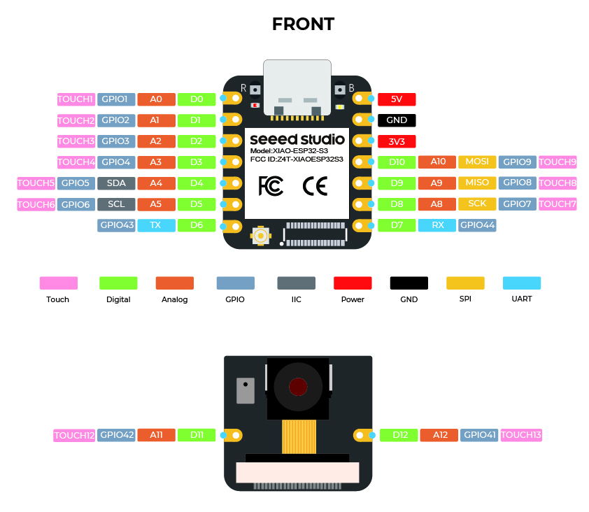
The default UART pins for the XIAO ESP32S3 are as follows (refer to the blue UART section in the pinout diagram):
| Pin Name | GPIO Number | Function Description |
|---|---|---|
| TX | GPIO43 | Serial Transmit (UART TX) |
| RX | GPIO44 | Serial Receive (UART RX) |
This pair of pins can be used to build a Serial1 (secondary UART) communication channel, making them ideal for node-to-node communication in this Fab Academy assignment.
Hardware Wiring Plan (Based on Pinout Diagram)
Wiring between two XIAO ESP32S3 boards:
| Node | Pin Name | GPIO | Connects To |
|---|---|---|---|
| Node 1 (Sender) | TX | GPIO43 | → Node 2’s RX (GPIO44) |
| Node 1 (Sender) | RX | GPIO44 | ← Node 2’s TX (GPIO43) |
| Both Ends | GND | Common Ground | GNDs of both boards are connected |
LED Module Wiring on Receiver Side:
| LED Pin | Connected GPIO | Arduino Pin Name |
|---|---|---|
| Signal | GPIO2 | D2 |
| VCC | 3.3V | — |
| GND | GND | — |
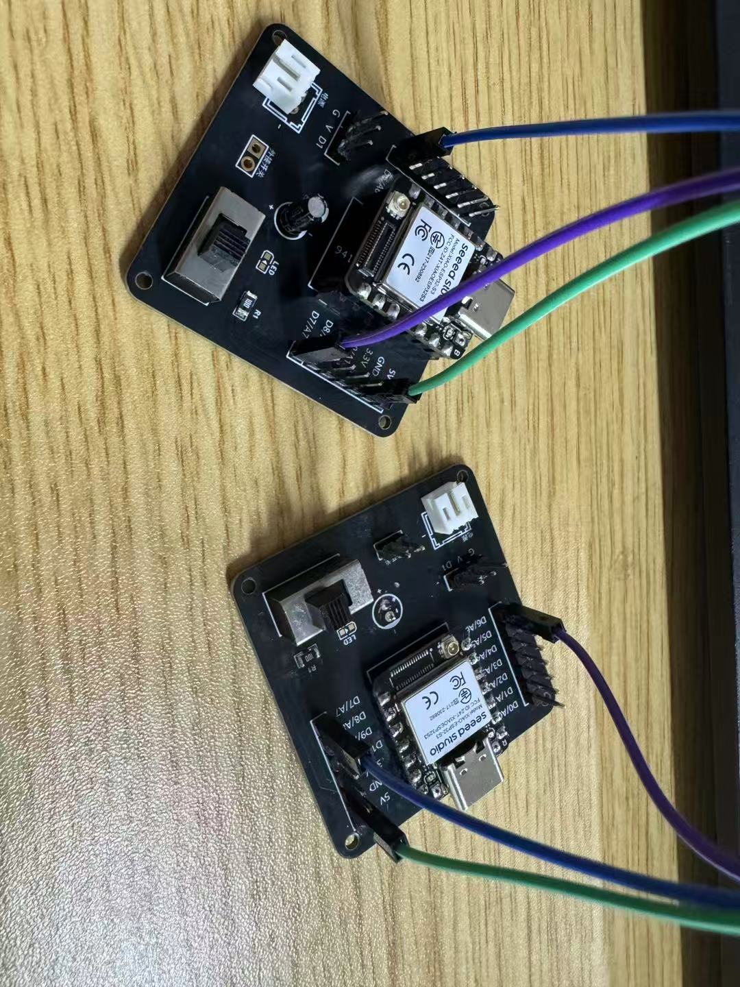
4. Hardware Connection
Bill of Materials:
| Item | Description | Quantity |
|---|---|---|
| XIAO ESP32S3 | Microcontroller board | 2 pcs |
| Breadboard | For connecting modules | 1 pc |
| Jumper wires | For wiring connections | ≥6 pcs |
| Single-color LED module | Used as output device | 1 pc |
| USB-C data cable | Power and upload code to XIAO | 2 pcs |
| Computer + Arduino IDE | For programming and uploading code | 1 set |
Wiring Instructions:
1. Communication wires between nodes (TX ↔ RX, RX ↔ TX, GND ↔ GND)
| Node | Pin | Connects To | Other Node Pin |
|---|---|---|---|
| Node 1 | TX (D6) | → Node 2 | RX (D7) |
| Node 1 | RX (D7) | ← Node 2 | TX (D6) |
| Node 1 | GND | — | Node 2 GND |
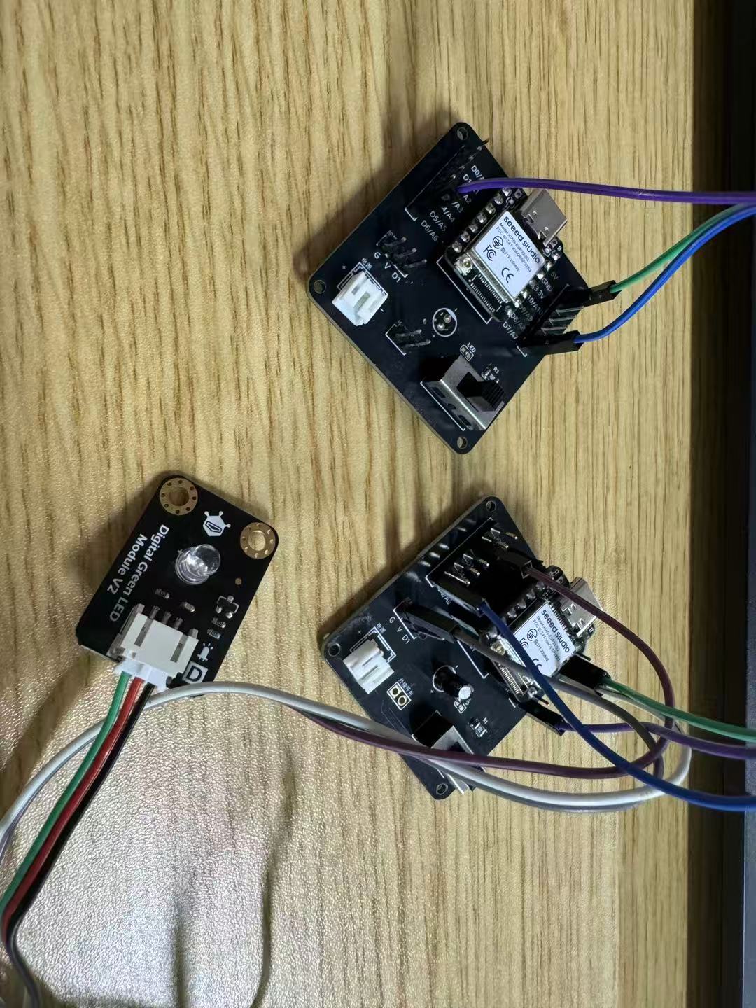
2. LED module on receiving node (Node 2)
| LED Pin | Connected to Node 2 Pin |
|---|---|
| Signal (long leg) | D2 (GPIO2) |
| VCC | 3.3V |
| GND | GND |
5. Arduino Code (for Both Nodes)
Before writing the code, I had some doubts about the baud rate for transmission, so I first researched related information and documented my findings.
ESP32S3 Baud Rate Is Not Fixed
The ESP32S3 supports a wide range of common baud rates:
| Baud Rate | Recommended | Notes |
|---|---|---|
| 9600 | ✅ Recommended | Stable, highly compatible, ideal for beginners and basic module communication |
| 19200 | ✅ | Slightly faster, still very stable |
| 38400 | ✅ | Common for debugging |
| 57600 | ✅ | Relatively fast |
| 115200 | ✅ Very common | Default for many serial monitors, also default USB serial speed for ESP32 |
| 250000, 500000, 921600 | ❗ Use with caution | High-speed use only; consider wire length, interference, and receiving device's capability |
🔧 How to Set Baud Rate in UART
To set the baud rate in Arduino for ESP32S3, use the following code:
Serial1.begin(9600, SERIAL_8N1, RX, TX); // 9600 is the baud rateYou can replace 9600 with any other supported baud rate:
Serial1.begin(115200, SERIAL_8N1, RX, TX); // Faster communicationSummary of Program Logic
| Sender (Node 1) | Receiver (Node 2) |
|---|---|
| Sends the string "Hello from Node 1" every second | Lights up the LED for 0.3 seconds upon receiving the string |
Uses UART communication via Serial1 |
Uses UART communication via Serial1 to read messages |
| Sends data via GPIO43 (TX) | Receives data via GPIO44 (RX) |
Node 1 (Sender) Code:
This code initializes UART communication using Serial1 on the XIAO ESP32S3. It sends a string "Hello from Node 1" every second to the receiver node.
#define XIAO_ESP32S3_D6
            #define XIAO_ESP32S3_D7
            #define TXD 43
            #define RXD 44

            void setup() {
            Serial1.begin(9600, SERIAL_8N1, RXD, TXD);
            }

            void loop() {
            Serial1.println("Hello from Node 1");
            delay(1000);
            }
Node 2 (Receiver) Code:
This code sets up UART communication using Serial1 on the XIAO ESP32S3 and configures a digital pin for controlling an LED. When it receives a message containing the word "Hello" from Node 1, it briefly lights up the LED.
#define XIAO_ESP32S3_D2
            #define XIAO_ESP32S3_D6
            #define XIAO_ESP32S3_D7
            #define TXD 43
            #define RXD 44
            #define LED_PIN 3

            void setup() {
            pinMode(LED_PIN, OUTPUT); // Set LED pin as output
            Serial1.begin(9600, SERIAL_8N1, RXD, TXD); // Initialize UART communication
            }

            void loop() {
            if (Serial1.available()) {
                String msg = Serial1.readStringUntil('\n'); // Read incoming serial message
                if (msg.indexOf("Hello") >= 0) {
                digitalWrite(LED_PIN, HIGH);  // Turn on LED
                delay(300);                   // Wait 300 ms
                digitalWrite(LED_PIN, LOW);   // Turn off LED
                }
            }
            }
6. Program Upload Steps
- Open the Arduino IDE;
- Plug in the Node 1 board and select the correct board and port:
- Go to Tools → Board → XIAO_ESP32S3
- Select the corresponding COM port (e.g., COMx)
- Upload the sender code to Node 1;
- Disconnect Node 1 and connect Node 2 via USB;
- Upload the receiver code to Node 2;
- Make sure TX/RX/GND are correctly connected between the two boards;
- Power both boards — the communication test will begin automatically.
7. Testing and Validation Process
After completing all hardware connections and uploading the programs, I began system testing to verify whether the nodes could communicate properly.
First, I powered both XIAO ESP32S3 boards by connecting them to the computer via USB data cables. Once powered, Node 1 (sender) started its main loop and transmitted a message "Hello from Node 1" via UART every second.
Meanwhile, Node 2 (receiver) continuously monitored the UART interface. Whenever it received a string containing the keyword "Hello", it triggered the LED module connected to GPIO2 to light up for 300 milliseconds, then turned it off automatically.
To verify the stability and responsiveness of the system, I performed the following tests:
- Test 1: Observe Normal Communication
- Opened the Serial Monitor and confirmed that Node 1 was sending a message every second;
- Observed that Node 2’s LED flashed once per second — this indicated successful communication;
- This confirmed the correctness of TX/RX connections and matched baud rates.
- Test 2: Modify Message Content
- Changed Node 1's message to
"LED_ON_SIGNAL"; - Updated Node 2 to trigger the LED only when receiving
"LED_ON"; - After uploading, the LED still responded correctly, showing the receiver can recognize specific message content.
Updated Node 1 (Sender) Code
This version of the sender code not only sends the message
"LED_ON_SIGNAL"viaSerial1every second, but also prints debugging output to the Serial Monitor viaSerial, which helps track transmission in real time.#define XIAO_ESP32S3_D6 #define XIAO_ESP32S3_D7 #define TXD 43 #define RXD 44 void setup() { Serial.begin(115200); // Debug output to Serial Monitor Serial1.begin(9600, SERIAL_8N1, RXD, TXD); // Initialize UART communication Serial.println("Sender setup complete."); } void loop() { Serial1.println("LED_ON_SIGNAL"); // Modified message content Serial.println("Sent: LED_ON_SIGNAL"); // Visible in Serial Monitor delay(1000); }Explanation:
- I changed the original message
"Hello from Node 1"to a more specific one:"LED_ON_SIGNAL". - This allows us to test whether the receiver can correctly match and respond to messages containing
"LED_ON". - I also added
Serial.println()statements to make it easier to observe the program status via the Serial Monitor.
Updated Node 2 (Receiver) Code
This code listens for UART messages using
Serial1, and if the incoming string contains"LED_ON", it briefly turns on an LED connected to GPIO2. It also prints all received messages and LED actions to the Serial Monitor for easier debugging.#define XIAO_ESP32S3_D2 #define XIAO_ESP32S3_D6 #define XIAO_ESP32S3_D7 #define TXD 43 #define RXD 44 #define LED_PIN 2 void setup() { pinMode(LED_PIN, OUTPUT); Serial.begin(115200); // Enable serial monitor output Serial1.begin(9600, SERIAL_8N1, RXD, TXD); // Initialize UART Serial.println("Receiver setup complete."); } void loop() { if (Serial1.available()) { String msg = Serial1.readStringUntil('\n'); // Read UART data Serial.print("Received: "); Serial.println(msg); // Print received string to Serial Monitor if (msg.indexOf("LED_ON") >= 0) { // Match command containing "LED_ON" digitalWrite(LED_PIN, HIGH); delay(300); digitalWrite(LED_PIN, LOW); Serial.println("LED blinked."); } } }Explanation:
- I used
msg.indexOf("LED_ON") >= 0to check whether the received command contains the keyword"LED_ON". - Since
"LED_ON_SIGNAL"includes"LED_ON", the condition is satisfied and the LED is triggered. - Added
Serial.print()andSerial.println()for debugging purposes and real-time feedback in the Serial Monitor. - If the string does not contain
"LED_ON", the LED will not blink, which confirms the condition works as expected.
- Changed Node 1's message to
- Test 3: Adjust LED Blink Duration
- Modified
delay(300)todelay(1000)in Node 2’s code; - The LED stayed on longer, making the blink more noticeable;
- This helped me better understand how
digitalWrite()anddelay()affect output device control.
- Modified
- Test 4: Fault Test – Disconnect TX Line
- Manually unplugged the jumper wire from Node 1’s TX to Node 2’s RX;
- The LED stopped blinking, confirming that communication was lost;
- Reconnecting the wire restored LED response, highlighting the importance of proper wiring.
Through these tests, I not only verified the functionality of the system but also deepened my understanding of UART communication — including TX/RX crossover, baud rate matching, and signal-triggered output. The overall testing process was smooth and met expectations.
Issues and Solutions
During the setup and testing process, I encountered a few minor problems. However, all of them were resolved through careful troubleshooting and learning. Below are some typical issues and how I solved them:
| Problem | Possible Cause | My Solution |
|---|---|---|
| LED not lighting up | Receiver did not receive data; condition not triggered | Checked if TX and RX were crossed correctly; verified message content and LED module functionality |
| Garbled output in Serial Monitor | Baud rate mismatch or incorrect configuration | Made sure Serial1.begin(9600) matches the baud rate in Serial Monitor |
| Receiver unresponsive | Serial1 not initialized or TX/RX pins not specified |
Added Serial1.begin(9600, SERIAL_8N1, RXD, TXD) with correct pin setup |
| Program upload failed | Board was busy or USB driver not recognized | Replugged USB cable, confirmed correct port in Arduino IDE, used BOOT button if needed |
This debugging process helped me realize that even the smallest detail — like the direction of one wire or a single configuration parameter — can directly affect the system’s operation.
Personal Assignment Summary
Through this individual assignment, I successfully completed a two-node communication system using XIAO ESP32S3 and UART serial communication.
During the entire process, I not only built two independent nodes—one as the sender and one as the receiver—but also mastered several key concepts:
- Learned how to use
Serial1.begin()to enable the second UART on the ESP32S3, and how to use specific pins (GPIO43 and GPIO44) for TX/RX communication; - Gained a deeper understanding of how UART communication works, including frame structure, baud rate, and the importance of crossing TX and RX connections;
- Successfully implemented code that sends a specific string from the sender, which is recognized by the receiver to control an LED — realizing a full loop from data communication to physical action;
- Performed multiple tests including changing message content, adjusting LED response time, and simulating faults to verify system stability;
- Learned to use
Serial.println()for real-time debugging in the Serial Monitor, improving development efficiency; - Also learned to troubleshoot common issues such as upload failures, garbled serial output, and unresponsive receivers—and resolved them successfully.
This experiment not only helped me fulfill Fab Academy’s requirements for node communication but also deepened my understanding of low-level communication between IoT devices. It lays a solid foundation for exploring more advanced protocols in the future, such as ESP-NOW or Wi-Fi MQTT.
The entire experience showed me that even a simple data exchange between two boards involves an interweaving of circuit design, data protocols, program logic, and debugging skills. By building and debugging it myself, I truly understood the core principles of “how devices talk to each other.”
Group Assignment
Send a Message Between Two Projects
1. Task Understanding
This Fab Academy group assignment requires us to:
- Implement communication between two self-created projects/devices;
- The communication method can be wired (e.g., UART) or wireless (e.g., Wi-Fi, BLE, ESP-NOW);
- The message content can include control commands, text, or status feedback;
- There must be a clear response to confirm that the message has been successfully transmitted.
2. Project Design Overview
I used two XIAO ESP32S3 development boards and implemented basic message exchange between the two devices using UART serial communication.
Functional Roles:
- Node A: Sends a request message
"Ping"every 3 seconds; - Node B: Upon receiving
"Ping", responds with"Pong"; - Node A: After receiving
"Pong", logs the message in the Serial Monitor to confirm successful communication.
When designing the functional roles, I considered whether to include bidirectional command execution. For example, upon receiving "Ping", Node B could not only reply with "Pong" but also trigger a local output action, such as blinking an LED, to provide a more intuitive physical response. However, I decided to first complete a minimal system to ensure the basic message exchange flow works properly, and then consider adding such extensions.
3. Hardware and Wiring Overview
Message channel: UART serial communication using GPIO43 and GPIO44
| Item | Node A GPIO | Node B GPIO |
|---|---|---|
| TX | GPIO43 | GPIO44 |
| RX | GPIO44 | GPIO43 |
| GND | GND | GND |
Hot-Plug Operation Supported:
I connected both development boards to the computer using two USB-C data cables. This allowed me to upload programs and power the boards simultaneously, making testing and debugging very convenient.
During the experiment, I found that the onboard USB port of the XIAO ESP32S3 provides sufficient power to support both communication and operation, without the need for an additional power supply module.
4. Code Design
Node A (Ping Sender)
This program initializes UART communication and sends the string "Ping" every 3 seconds via Serial1. It also prints the sent message to the Serial Monitor for debugging purposes.
                #define XIAO_ESP32S3_D6
                #define XIAO_ESP32S3_D7
                #define TXD 43
                #define RXD 44

                void setup() {
                Serial.begin(115200);  // For debug output
                Serial1.begin(9600, SERIAL_8N1, RXD, TXD);  // UART initialization
                Serial.println("Node A ready. Sending Ping...");
                }

                void loop() {
                Serial1.println("Ping");  // Send Ping
                Serial.println("Sent: Ping");  // Log to Serial Monitor
                delay(3000);  // Wait 3 seconds before sending again
                }
Node B (Pong Responder)
This program listens for UART input using Serial1. When it receives the string "Ping", it responds by sending "Pong" back and logs both the received and sent messages to the Serial Monitor for debugging.
                #define XIAO_ESP32S3_D6
                #define XIAO_ESP32S3_D7
                #define TXD 43
                #define RXD 44

                void setup() {
                Serial.begin(115200);  // For debug output
                Serial1.begin(9600, SERIAL_8N1, RXD, TXD);  // UART initialization
                Serial.println("Node B ready. Waiting for Ping...");
                }

                void loop() {
                if (Serial1.available()) {
                    String msg = Serial1.readStringUntil('\n');  // Read message
                    Serial.print("Received: ");
                    Serial.println(msg);

                    if (msg.indexOf("Ping") >= 0) {
                    Serial1.println("Pong");  // Send response
                    Serial.println("Sent: Pong");
                    }
                }
                }
While writing the program, I also experimented with abstracting the communication logic into functions. For example, I encapsulated the sending and receiving operations into sendMessage() and waitForMessage() functions respectively. This made the program logic clearer and will make it easier to scale the system into a more complex command-based architecture in the future.
5. Experiment Procedure and Testing Steps
- Open two separate Arduino IDE windows and connect each board individually;
- Upload the Ping sending program to Node A;
- Upload the Pong response program to Node B;
- Open the Serial Monitor for both boards simultaneously and observe the log outputs:
- Node A prints
"Sent: Ping"every 3 seconds; - Node B displays the received
"Ping"and then sends back"Pong"; - Node A displays the received
"Pong"— confirming successful communication.
- Node A prints
Additional Reflection: Handling Delays and System Stability
I also considered an important question: What if Node B responds slowly — would Node A timeout too early?
To explore this, I added a longer delay for waiting and attempted to measure the time difference between sending and receiving messages. This helped me begin designing a future timeout mechanism.
In addition, to prevent message duplication or system blocking, I explored whether I could implement message queuing or switch to non-blocking reads (e.g., using Serial1.read() instead of readStringUntil()).
Although these improvements were not added in the final implementation, the process helped me better understand the relationships among communication buffering, blocking I/O, and system stability.
Reflection and Takeaways
This assignment marked the first time I truly achieved “device-to-device dialogue”.
Unlike the one-way transmission in my individual assignment, this task required deeper thinking:
- Which node should speak first?
- After sending a message, how can I confirm it was received?
- What logic should be used to trigger a response?
- Should I implement waiting, retries, or detect if the peer is offline?
I not only learned how to use UART for two-way communication, but also began to understand how to design simple software protocols. I built a basic communication coordination scheme, starting with a minimal "Ping-Pong" structure and gradually exploring how to scale the logic.
This experiment went beyond surface-level interaction — it gave me a genuine understanding of the practical considerations behind developing communication between devices. For me, it was a shift from simply “getting it to work” to designing something structured, scalable, and reliable.
As a result, I now have a stronger foundation for working with more advanced communication protocols like ESP-NOW or MQTT, and a clearer idea of how to organize multi-device communication systems in future projects.