Output Devices
Back to HomeGoals
group assignment
- measure the power consumption of an output device
Individual Assignment
- add an output device to a microcontroller board you've designed, and program it to do something
Group Assignment
Objective
The task of this group assignment is to select an output device, measure its current consumption during operation, and calculate its power consumption based on that.
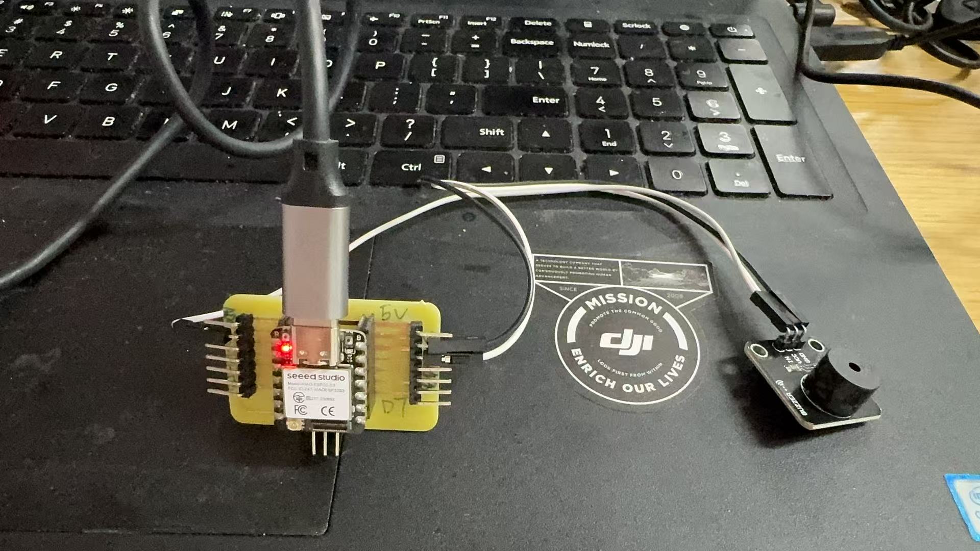
We selected an active buzzer as the output device. By making it produce sound, we determined that it was in the working state. Then, we used the FNIRSI 2C23T oscilloscope + multimeter combo device to measure the current. Finally, we calculated the actual power consumption of the buzzer by multiplying the supply voltage of the microcontroller board by the measured current.
Measurement Principle
A buzzer is a type of output device. When a high-level signal or PWM signal is applied to its control pin, it emits sound and draws a certain amount of current from its power supply.
We can calculate its operating power using the following formula:
Power P (W) = Voltage U (V) × Current I (A)
To measure the current, we need to connect the multimeter in series with the power supply path of the buzzer. This way, the current flowing through the buzzer during operation will pass through the multimeter, allowing it to display the real-time current value.
Materials and Tools
| Name | Quantity | Description |
|---|---|---|
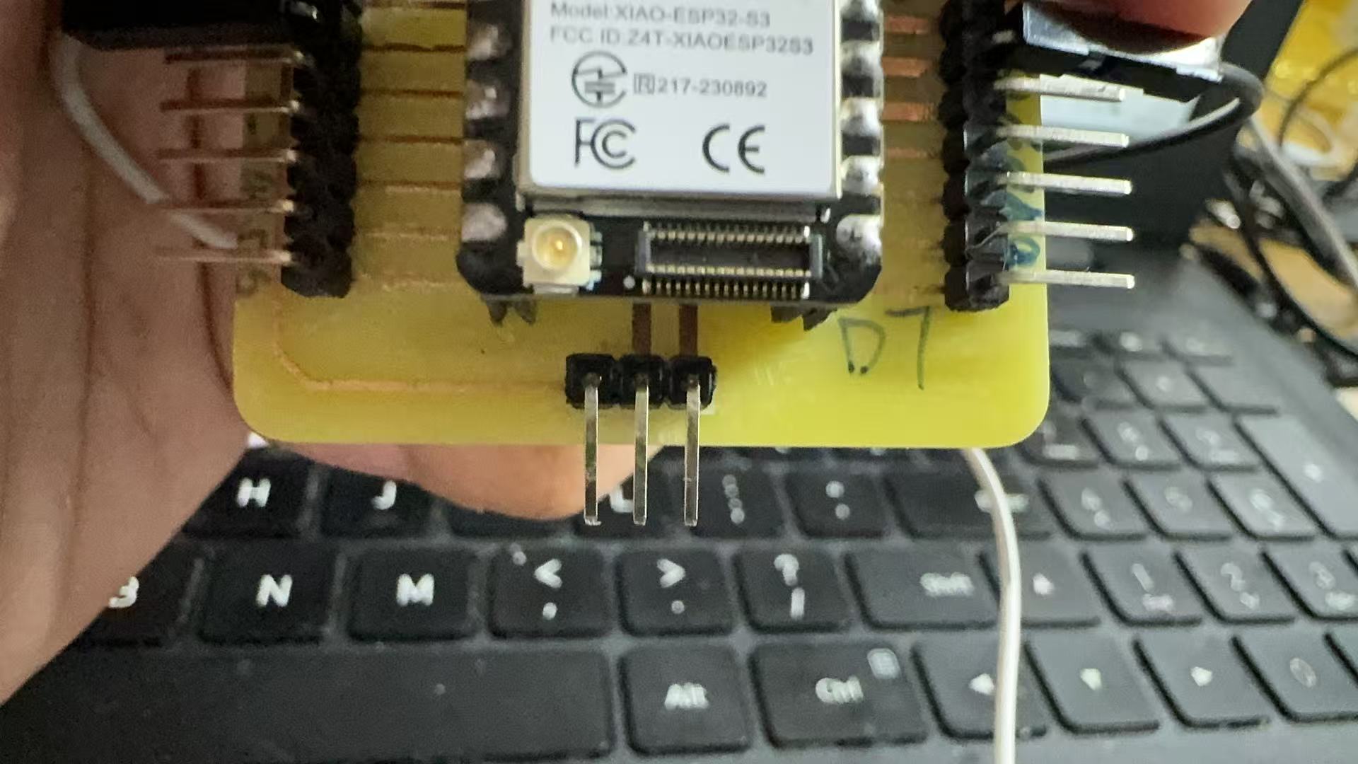
| Seeed XIAO ESP32S3 Microcontroller | 1 | Controls the buzzer |
| Active Buzzer | 1 | Emits sound when working |
| Dupont Wires | Several | Used to manually connect the circuit |
| FNIRSI 2C23T Oscilloscope / Multimeter | 1 | Used for measuring current |
| USB Type-C Cable | 1 | Supplies power and uploads programs |
| Arduino IDE | 1 | Used to upload the test program |
Note: We did not use a breadboard. Instead, we manually completed the circuit and measurements using Dupont wires and multimeter probes.
Learning Process & Reflections
During the experiment, I didn't know how to measure current at the beginning. I encountered several key issues and gradually solved them through asking questions and hands-on attempts:
First issue: I didn’t understand how to “measure power consumption” in the group assignment.
Initially, I was unclear about what the task required. I didn’t know how to perform a power measurement. Later, after reading instructions and consulting the teaching assistant, I realized that I needed to measure the current drawn by the buzzer, then multiply it by the voltage to calculate the power consumption, instead of reading power directly from the oscilloscope.
Second issue: I didn’t know how to use the multimeter to measure current, nor the difference between the mA and 10A ports.
At first, I thought I could simply point the multimeter at the device to get a current reading. I later learned that to measure current, the meter must be connected in series with the circuit, unlike voltage measurement which uses a parallel connection.
I also learned:
| Range | Usage |
|---|---|
| 10A | Use this at the beginning to avoid damaging the meter |
| mA | Use this for small current (<200mA) for better precision |
In the end, I used the configuration of the red probe in the 10A port and the black probe in the COM port to measure the current.
Third issue: The AUTO button didn’t switch modes—how do I get the multimeter into current measurement mode?
I tried to switch modes manually using the AUTO button, but it didn’t work. Later, I found out that the FNIRSI 2C23T identifies the measurement type based on probe port positions and whether current is actually flowing. So I had to connect the wires correctly and make the buzzer sound—only then would the device switch to current measurement mode.
This issue taught me that the instrument is not manually controlled by buttons but switches modes based on triggered behavior.
Fourth issue: The buzzer made sound, but I wasn’t sure if the measurement was successful.
Once the buzzer started sounding, I observed the multimeter screen displaying “19.00” with a unit of mA below. That’s when I confirmed I had successfully measured the current. From this point, I began to understand current measurement more confidently.
Circuit Connection
I used Dupont wires to connect the XIAO microcontroller, the buzzer, and the multimeter. The connection method is as follows:
                [XIAO 5V] → Red probe (inserted into multimeter 10A port)
                                        ↓
                            Multimeter (current measurement)
                                        ↓
                        Black probe (inserted into COM port) → Buzzer VCC
                Buzzer GND → XIAO GND
                Buzzer signal pin → XIAO D2
Code for Testing
The following program controls the buzzer through GPIO to beep once per second, making it easier for me to observe the current fluctuation.
                #define BUZZER_PIN 2

                void setup() {
                pinMode(BUZZER_PIN, OUTPUT);
                }

                void loop() {
                digitalWrite(BUZZER_PIN, HIGH); // Buzzer ON
                delay(1000);
                digitalWrite(BUZZER_PIN, LOW);  // Buzzer OFF
                delay(1000);
                }
How I Used the Multimeter
- Inserted the probes: red probe → 10A port, black probe → COM port
- After completing the circuit connection, I powered the board and ran the program
- Once the buzzer started sounding, the multimeter automatically switched from AUTO mode to A mA
- The display showed a reading of: 12.00mA ~ 17.00 mA
This indicated that I had successfully measured the working current of the buzzer.
Measurement Results and Power Calculation
| Current Value | Power Calculation Formula | Result |
|---|---|---|
| 12 mA (0.012 A) | 5 × 0.012 | 0.060 W |
| 17 mA (0.017 A) | 5 × 0.017 | 0.085 W |
| Average ~14.5 mA (0.0145 A) | 5 × 0.0145 | 0.0725 W |
The display showed that the current fluctuated between 12.00 mA and 17.00 mA, with the unit being mA. This indicates that the current drawn by the buzzer continuously varies during operation. The fluctuation might be related to the way the program controls the buzzer or to the internal oscillation frequency of the buzzer itself.
Text Video
Group Reflection
This group assignment was not only a hands-on practice in current measurement, but also a deeper exploration into power consumption, a core parameter in electronic systems. Although the task sounded simple—“measure the power consumption of an output device”—we encountered several conceptual and operational challenges during execution.
We started with a vague understanding of the task and gradually learned the basic principle that Current × Voltage = Power. Then, we learned how to properly use a multimeter—especially how to measure current in series. Each stage brought meaningful learning.
In particular, while using the FNIRSI 2C23T multifunction multimeter, we went through multiple trials and errors:
- At first, we didn’t understand why pressing the AUTO button didn’t work;
- Later, we realized that this device switches measurement modes automatically through probe placement + current flow;
- We also learned that for current to be measured, it must flow through the multimeter itself;
- Once the multimeter showed a reading, we needed to interpret the units (e.g., mA), convert them to amperes, and use them with voltage to calculate power.
We also noticed an interesting phenomenon: the buzzer's current was not stable during operation, but fluctuated between 12–17 mA. This helped us realize that power consumption is a dynamic metric that can vary over time. Therefore, we recorded the minimum, maximum, and average current values, and calculated corresponding power values to better reflect the device's behavior.
Through this experiment, we not only completed the measurement task, but also established a full thinking chain:
Output device operates → Current fluctuates → Multimeter reads value →
Combine with voltage to calculate power → Analyze variation and significance →
Apply to device evaluation and energy-efficient design
This process will be very helpful for our future understanding of output devices and more complex systems such as motors, LED matrices, and communication modules.
Conclusion
In this group assignment, we selected an active buzzer as the output device. Using the XIAO ESP32S3 to control its sound output, we measured the current during operation and calculated its power consumption based on the supply voltage (5V).
According to the actual measurements from the FNIRSI 2C23T multimeter:
- The current fluctuated between 12–17 mA (0.012–0.017 A) while the buzzer was sounding;
- The corresponding power consumption ranged from 0.060 W to 0.085 W;
- Based on the fluctuation range, the estimated average current was around 14.5 mA (0.0145 A), resulting in an average power of approximately 0.0725 W.
This indicates that the active buzzer is a very low-power output device, making it suitable for low-energy systems or battery-powered applications.
More importantly, through this assignment we learned:
- How to properly connect and use a digital multimeter to measure DC current;
- How to extract average values from fluctuating data for evaluation;
- How to combine theoretical knowledge (P = U × I) with real-world measurements;
- How to break down a seemingly simple task into multiple hands-on and learnable steps.
We believe that “measuring power consumption” is not just a technical operation, but a key process that bridges device performance understanding → system design → energy efficiency awareness.
Individual Assignment
Task Understanding
According to the individual assignment for the Fab Academy Output Devices module, I am required to:
- Add an output device to a microcontroller board I designed (or one that is compatible);
- Program it to perform an action, completing the full chain from code to physical behavior.
At first, I was torn between using a buzzer or an LED. However, since I had reserved a dedicated servo motor interface when designing my own control board, I decided to use a servo motor as the output device. This not only allowed me to fulfill the assignment, but also served as a test to verify the practicality and reliability of the board I designed.
Why Servo Motor?
I ultimately chose a servo motor (model: SG90) for the following reasons:
- A servo allows precise angle control, and its movement is intuitive and visible;
- Unlike buzzers or LEDs which only produce sound or light, a servo generates motion, making it a highly representative output device;
- My expansion board includes a dedicated 3-pin servo connector (GND / 5V / Signal), and I wanted to test its reliability;
- Controlling a servo requires PWM (Pulse Width Modulation) signals, which helps me deepen my understanding of PWM;
- Servo motors are widely used in mechanical and robotics projects, so I wanted to get familiar with them in advance.
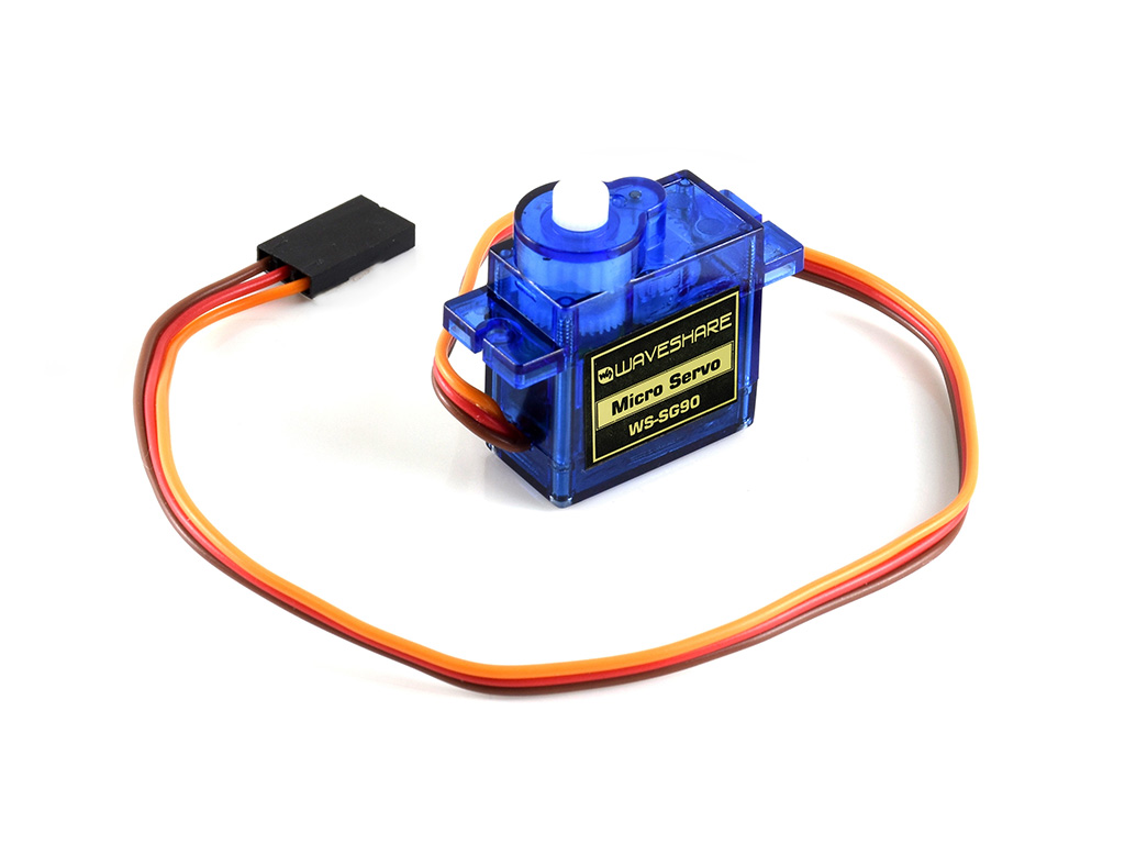
The SG90 is a popular small-sized servo motor produced by Tower Pro, with many compatible versions available. Due to its compact size, simple structure, and ease of control, the SG90 is widely used in Arduino projects, educational robots, robotic arms, RC models, and smart devices.
Key Specifications
| Item | Specification |
|---|---|
| Type | Analog Servo |
| Operating Voltage | 4.8V – 6.0V (Recommended: 5V) |
| Rotation Range | 0°–180° (some variants support 0°–270°) |
| Control Signal | PWM signal (standard period ≈ 20 ms) |
| PWM Duty Cycle | 0°: 0.5 ms, 90°: 1.5 ms, 180°: 2.5 ms |
| Torque | 1.8 kg·cm @ 4.8V |
| Speed | 0.1 sec/60° (no load) |
| Motor Type | Small DC motor + Gearbox |
| Wire Colors | Brown (GND), Red (VCC), Orange (Signal) |
How It Works
The SG90 servo motor is controlled by PWM signals. A controller (e.g., XIAO ESP32S3) sends a pulse every 20 ms, with the pulse width determining the servo’s position:
- 0.5 ms pulse → 0°
- 1.5 ms pulse → 90°
- 2.5 ms pulse → 180°
The SG90 contains an internal potentiometer and control circuit for closed-loop feedback, allowing it to hold its position even under light loads.
Wiring
| Wire Color | Function | Connect To |
|---|---|---|
| Brown | Ground (GND) | Microcontroller GND |
| Red | Power (VCC) | Microcontroller 5V |
| Orange | PWM Signal | GPIO pin |
Advantages
- Inexpensive and widely available
- Simple control, suitable for beginners
- Smooth motion, ideal for teaching and light-duty tasks
- Highly compatible with Arduino, ESP32, Raspberry Pi, etc.
- Low power consumption; can be powered via USB
Notes
- Not continuous rotation: SG90 is a positional servo, limited to a fixed angle range
- Do not overload: excessive load can cause overheating, jittering, or damage
- PWM signal must be stable; otherwise, the servo may behave erratically
- For long-term operation, consider using voltage regulators or capacitors to prevent voltage fluctuations
Servo Control and Upload Process
To control the servo via programming, I used the Arduino IDE as the development environment and connected the SG90 servo through the expansion board I designed for the XIAO ESP32S3. Throughout the process, I carefully recorded key steps such as setting up the software environment, installing the servo library, writing the code, and uploading/debugging.
Step 1: Prepare Arduino IDE Environment
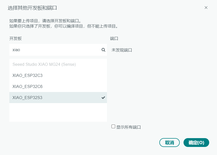
- I used Arduino IDE version 2.3.4
- Go to Tools > Board, and select:
XIAO_ESP32S3
Step 2: Install the Servo Control Library
The servo needs to be controlled using PWM signals, so I installed the ESP32Servo.h control library in Arduino:
- Open Arduino IDE
- Go to Tools > Manage Libraries
- In the Library Manager, search for ESP32Servo
- Locate the ESP32Servo library published by Arduino (Author: Michael Margolis)
- Click Install
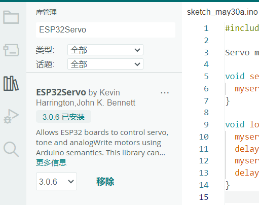
After installation, ESPServo.h is available for ESP32 and works correctly with the XIAO ESP32S3 board.
Step 3: Confirm Servo Connection (Using Expansion Board Interface)
My custom expansion board includes a standard 3-pin servo connector (GND / 5V / Signal), with the signal pin connected to D1 (GPIO 1). The servo is powered directly by the 5V from the USB. The wiring is as follows:
| Servo Wire Color | Function | Connected To |
|---|---|---|
| Brown | GND | GND on expansion board |
| Red | VCC | 5V |
| Orange | Signal | GPIO 1 (D1) |
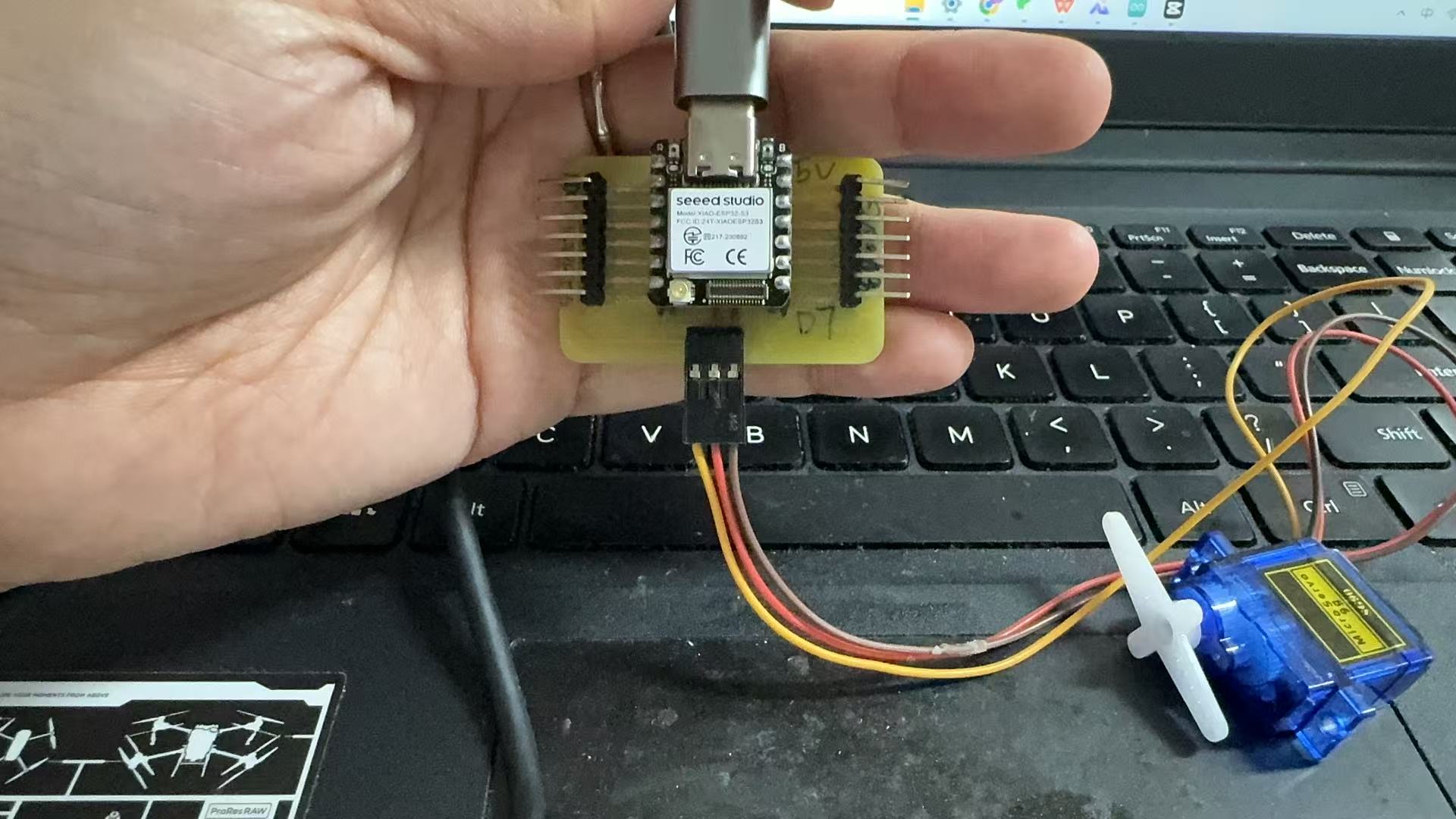
Once the servo is plugged in, no jumper wires are needed. The wiring is clean and secure.
Programming and Library Selection
The servo program uses the ESP32-specific Servo control library:
                        #define XIAO_ESP32S3_D1 2
                        #include

                        Servo myservo;

                        void setup() {
                          myservo.attach(2);  // XIAO ESP32S3 的 D1 对应 GPIO1
                        }

                        void loop() {
                          myservo.write(0);   // 转到 0 度
                          delay(1000);
                          myservo.write(90);  // 转到 90 度
                          delay(1000);
                          myservo.write(180); // 转到 180 度
                          delay(1000);
                        }
This simple program rotates the SG90 servo to three positions (0°, 90°, and 180°) at one-second intervals. It confirms that:
- The PWM signal is correctly generated from GPIO1 (D1);
- The servo responds accurately to control commands;
- The
ESP32Servolibrary is compatible with XIAO ESP32S3.
Monochrome LED Module Control Process
In addition to the servo motor, I also tested a monochrome LED module as an output device. This module includes a built-in current-limiting resistor, allowing it to be directly connected to the board.
Wiring Description
| LED Pin | Connected To |
|---|---|
| VCC | 3.3V |
| GND | GND |
| Signal | GPIO2 (D2) |
Note: The LED module lights up with a HIGH signal and is controlled using digitalWrite().
Control Code (Arduino IDE)
The following program controls a monochrome LED connected to GPIO3 (D2) on the XIAO ESP32S3 board. It turns the LED on and off at 0.5-second intervals.
                        #define XIAO_ESP32S3_D1
                        #define LED_PIN 3  // Connected to D2

                        void setup() {
                        pinMode(LED_PIN, OUTPUT);
                        digitalWrite(LED_PIN, HIGH);  // Turn on LED initially
                        }

                        void loop() {
                        digitalWrite(LED_PIN, HIGH);  // LED ON
                        delay(500);
                        digitalWrite(LED_PIN, LOW);   // LED OFF
                        delay(500);
                        }
This confirms that:
- GPIO3 (D2) functions correctly as a digital output;
- The LED module responds to the
digitalWritecommands; - My custom board can successfully drive a real physical output device using simple code.
Conclusion and Reflection
In this Output Devices assignment, I went through several attempts and revisions before successfully completing control of two output devices: the SG90 servo and a monochrome LED module. During the process, I not only mastered technical procedures, but also deepened my understanding of debugging and integrating hardware and software.
Failures and Troubleshooting
Initially, I planned to use my self-designed XIAO ESP32S3 expansion board to control the servo motor, with the control signal connected to pin D1. During programming in Arduino IDE, I encountered multiple compilation errors and a lack of response after uploading. I tried the following:
- Using the standard Servo library – reported incompatibility with ESP32
- Switching to the ESP32Servo library – encountered "header file not found" error
- Adjusting PWM channels and duty cycles – no response from the servo
- Changing GPIO pins (D1 → D6) – slight movement during upload but no sustained motion
After researching the issue, I found the root cause: I forgot to add the macro definition #define XIAO_ESP32S3_D1 in my code. Without this, the D1 pin name couldn't be recognized during compilation, which affected the PWM control. After including this definition and correctly importing the ESP32Servo library, the servo worked properly.
Successful SG90 Servo Control
Once the header issue was resolved and wiring confirmed, I achieved a smooth oscillation of the servo between 0° and 180°. From this process, I learned:
- The relationship between PWM signals and servo angles
- How to use the
ledcWrite()function and ESP32Servo library on ESP32 - Current fluctuation during servo operation (measured at 12–17mA using a multimeter)
- The importance of stable power supply separation for servo control
Attempt with Monochrome LED Module
In addition to the servo, I also tested a monochrome LED module as another output device. Initially, the LED did not light up. After troubleshooting, I found it was due to incorrect use of PWM functions and uninitialized GPIO pins. After correcting the ledcSetup() and ledcAttachPin() configuration, and confirming the GPIO macros, the LED successfully blinked on and off at a 500ms interval, demonstrating basic digital output control.
Learning Outcomes
- Understood ESP32 PWM control principles and channel configuration
- Learned to manually define GPIO macros (e.g.,
#define XIAO_ESP32S3_D1) for proper pin usage on XIAO ESP32S3 - Gained basic skills in using a multimeter to measure power consumption of devices like a buzzer
- Developed troubleshooting strategies for common errors: compilation failures, pin misconfigurations, and power issues
- Strengthened the understanding of the relationship between digital control signals and physical outputs