Final Project
Back to Home1. Project Background and Motivation
Throughout my journey in Fab Academy, I’ve always been fascinated by “things that move”—especially robots that combine bionic structures, mechanical behavior, and interactive capabilities. After completing the mechanical design assignment, I became even more determined to build a robot with “personality.”
So, my final project started with a simple idea:
“Can I build a robot that avoids humans—and looks like a mechanical spider?”
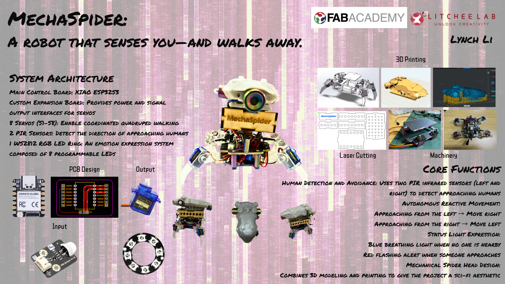
This MechaSpider project is my attempt to integrate all the skills I’ve learned over the past few months. It not only moves and senses human presence, but also expresses its state using RGB lighting. Its spider-like head was personally designed, modified, and 3D printed by me, giving it a sci-fi vibe and a touch of coolness.
2. Functional Goals
At the beginning of the project, I set several clear functional goals for myself:
- The robot's body adopts a quadruped structure, with each leg having two degrees of freedom (hip and knee joints);
- Use PIR infrared sensors to achieve "perception" capability, detecting whether a person is approaching from the left or right side;
- When detecting the direction of a person, the robot should "react" by moving in the opposite direction;
- Use a WS2812 RGB LED ring to express system status:
Blue breathing light = resting;
Red flashing light = alert; - Integrate all servos and sensors into a custom-designed expansion board to improve system stability and maintainability.
3. Project Structure Overview
Structural Divisions:
- Motion System: Composed of 8 SG90 servo motors, controlling the forward/backward swing and up/down lift of the four legs;
- Perception System: Two PIR infrared sensors located at the front-left and front-right of the robot;
- Expression System: One RGB LED ring with 8 WS2812 addressable LEDs;
- Control System: Core controller is the XIAO ESP32S3, paired with a custom-designed expansion board;
- Power System: Powered through a battery module.
4. Appearance Design and 3D Printing Process (Detailed)
I wanted this robot to not only move, but also to look special—not just with a biomimetic structure, but with a mechanical creature’s personality. Therefore, beyond its functional behavior, I spent considerable time refining its appearance and structural details.
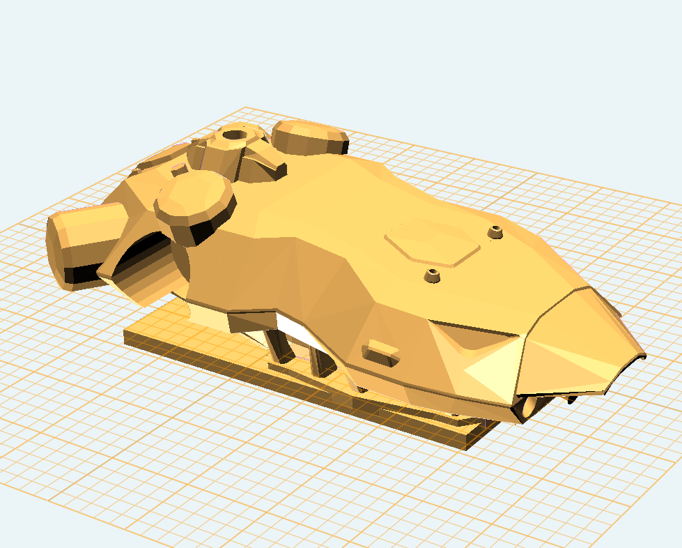
Spider Head Design: Download + Modification + SLA Printing
The head design was based on a mechanical spider model I found in the Bambu Lab community. The original model already had a futuristic look, but in order to adapt it to my robotic platform, I made several functional modifications using Rhino:
- Expanded internal space: The original model was only a decorative shell. I expanded the interior to fit the WS2812 LED ring;
- Added a mounting ring at the bottom: This allows the head to snap onto the main body structure, making it easier to assemble and maintain.
4. Appearance Design and 3D Printing Process (Detailed)
I wanted this robot to not only move, but also to look special—not just with a biomimetic structure, but with a mechanical creature’s personality. Therefore, beyond its functional behavior, I spent considerable time refining its appearance and structural details.
Spider Head Design: Download + Modification + SLA Printing
The head design was based on a mechanical spider model I found in the Bambu Lab community. The original model already had a futuristic look, but in order to adapt it to my robotic platform, I made several functional modifications using Rhino:
- Expanded internal space: The original model was only a decorative shell. I expanded the interior to fit the WS2812 LED ring;
- Added a mounting ring at the bottom: This allows the head to snap onto the main body structure, making it easier to assemble and maintain.
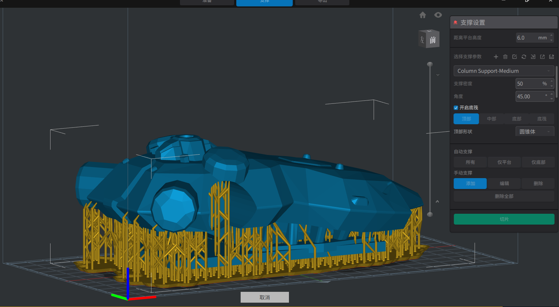
Printing Process: From FDM to SLA
Because the head structure was highly complex and rich in detail, I initially tried printing it with FDM (PLA material), but soon encountered several issues:
- Some holes and thin walls could not be clearly formed;
- Excessive layer lines negatively affected the visual quality;
- Post-processing was time-consuming and tedious.
In the end, I chose to use the lab’s SLA printer (LCD type, resin material) for high-precision printing. The results were outstanding:
- Full detail retention
- Virtually no visible layer lines
- Natural light diffusion, producing a “mechanical eye” effect
Mechanical Body Structure Design: SolidWorks Modeling + PLA Printing + SLA Printing + Laser Cutting
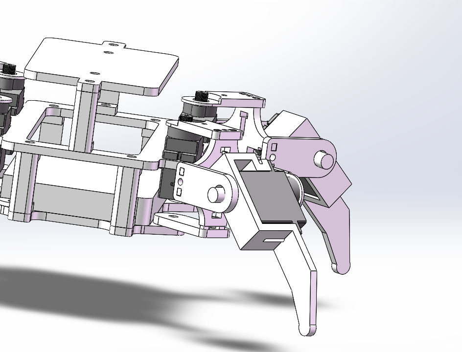
The main body structure of the robot—including the four legs, central chassis platform, electronics holder, and sensor mounts—was entirely modeled in SolidWorks.
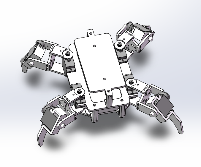
Design Logic:
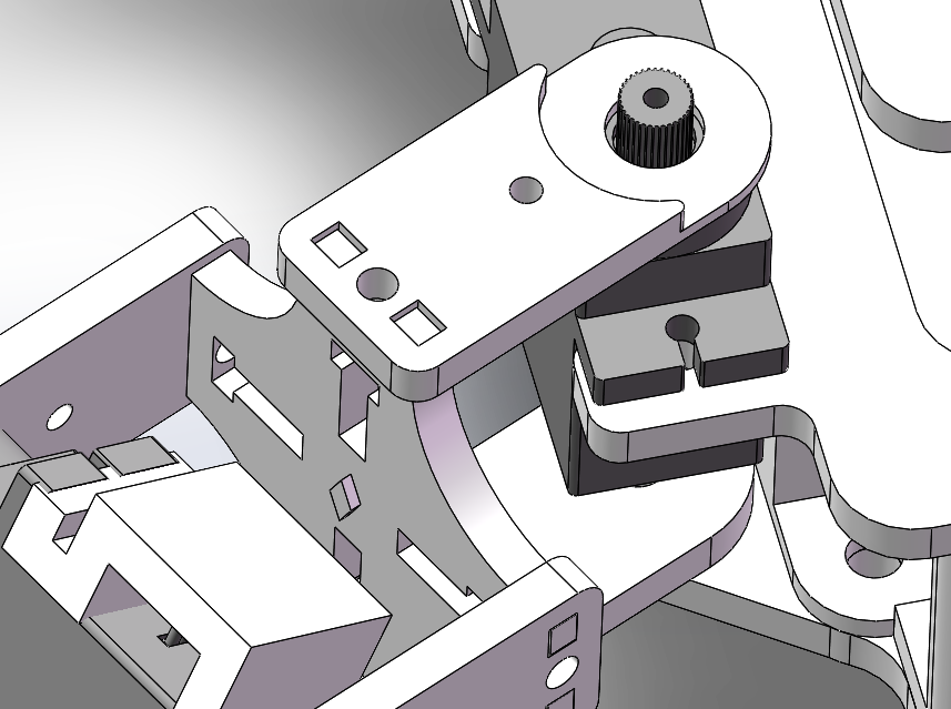
- Quadruped Legs (Driven by 8 Servos)
Each leg consists of two parts: an upper "thigh" and a lower "calf", controlled by two servo motors.- Servos are mounted in a cantilevered configuration, secured with printed connectors;
- All joints include pre-reserved M3 screw holes for easier assembly and maintenance;
- The lower part of the calf is thickened to increase ground contact area and standing stability.
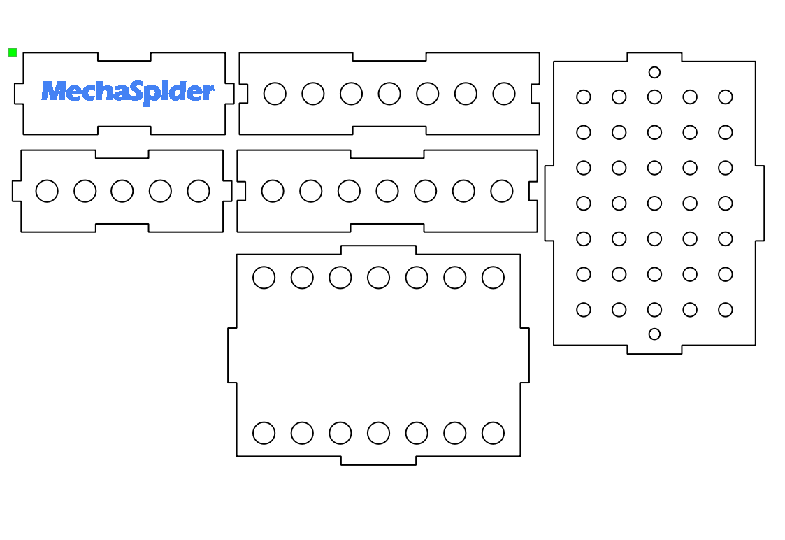
- Central Chassis
This section was partially fabricated using laser cutting techniques.- The top layer holds the ESP32 main control board and power supply;
- The middle layer houses the custom expansion board and wiring;
- The bottom layer provides space for the battery and cable storage.
- PIR Sensor Mounts
On the rear left and right of the mechanical spider head, I added two cylindrical decorative components to mount the PIR modules.- The structure uses snap-fit slots for assembly, making installation and removal easy.
- Double-sided routing with compact layout;
- Integrated all GPIO pins of the ESP32S3 mainboard;
- Specially designed pin headers for external modules such as servos, sensors, and LED lights;
- Added indicator LEDs, capacitors, and power ports to enhance stability and visibility.
- Understood the logic of through-hole connections between the top and bottom layers of double-sided PCBs;
- Learned to use the silk layer to label pin definitions, improving maintainability;
- Gained experience in communicating PCB details with the manufacturer (e.g., board thickness, hole size, plating process).
- Detect which side a person approaches from using the left and right PIR sensors;
- Drive 8 servos to control the robot's legs and perform avoidance movements;
- Use a WS2812 RGB LED ring to express the robot’s current state (idle / alert);
- Ensure system stability, fast response, and multitasking capability.
- Servo Control: Uses
ESP32Servo.hto define 8 servo instances; - RGB LED Control: Uses
Adafruit_NeoPixelto control the LED ring; - PIR Sensors: Reads digital input using
digitalRead(). - Read PIR sensor states (left and right);
- Determine if a person is approaching from either side;
- Based on the result, control the servo motion and LED behavior;
- If no one is nearby, enter the default idle mode with a blue breathing light and stable stance.
- A signal logic table on the left
- A top-down structure diagram in the center
- A forward gait flow and turning gait flow on the right
- Left front leg (LF) & right rear leg (RR) lift
delay- LF & RR swing forward
- Right front leg (RF) & left rear leg (LR) swing backward
delay- LF & RR lower
delay- RF & LR lift
delay- RF & LR swing forward
- LF & RR swing backward
delay- RF & LR lower
- Lift left front leg & right rear leg
- Swing them backward
- Swing right front leg & left rear leg forward
- Lower all legs
- Lift front and back right legs (S3, S7);
- Swing S4 and S8 to the right;
- Put legs down to complete movement.
- Uses PWM-like brightness modulation to simulate breathing;
- Each cycle takes about 2 seconds;
- Effect: “Dark blue → Light blue → Dark blue” slow pulse.
- Rapid red blinking;
- Triggered during avoidance movement;
- Simulates “alert” biological response.
- One PIR sensor installed on each front side of the robot
- Connected to separate GPIO pins
- Input checked every 200 ms using
digitalRead() - One-time trigger per detection with delay to avoid false repeats
- Stable within 0.5 meters
- Responsive to motion; suitable for indoor settings
- Performs best under stable lighting
- 8 SG90 servos controlled via PWM from XIAO ESP32S3
- Each leg uses 2 servos: knee (up/down) and hip (forward/backward)
- Indexed and encapsulated in code functions
- Designed multiple actions: stand, forward, turn, lift
- Followed “lift → swing → drop” gait logic
- All motions limited to safe servo angle ranges
- Simulates walking on flat surfaces
- Stable when powered by external 5V source
- 8-pixel WS2812 RGB LED ring embedded in head
- Controlled with Adafruit_NeoPixel library
- Two light modes:
- Blue breathing: idle mode with pulsing effect
- Red flashing: alert mode triggered during motion
- Non-blocking
millis()used for synchronized control - Visible through spider’s eye holes for "mechanical life" effect
- Blue pulse is smooth and steady
- Red flashing syncs with servo actions
- Visible in all lighting; no flickering
- Modeled in Rhino, remixed from Bambu Lab spider model
- SLA printed with high surface quality
- Internal space redesigned to hold LED and wires
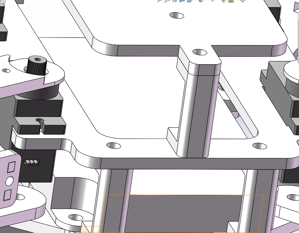
- Legs modeled in SolidWorks for strength and precision
- Chassis designed for easy maintenance and assembly
- All parts tightly assembled
- Servo mounts are precise—no sanding required
- Single-layer PCB CNC-milled and soldered
- Connects ESP32S3 to all peripherals
- No loose connections or dropouts
- Power system handles 8 servos + 1 LED ring + 2 PIRs
- Compact layout, strong soldering, easy maintenance
5. Custom Expansion Board and Circuit Design (Including Week 8 PCB Production Experience)
To make the connections, debugging, and replacement of each part of my robot clearer and more manageable, I placed special emphasis on learning and practicing circuit design and modular wiring throughout the Fab Academy journey.
During Week 8's electronics design and production assignment, I designed and produced two PCBs, which laid the foundation for my final project.
First Board: Double-layer PCB (Fabricated via JLCPCB)
This was my first attempt at designing a double-sided PCB. I used EasyEDA for the design and ordered the prototype from JLCPCB.
Board Features:
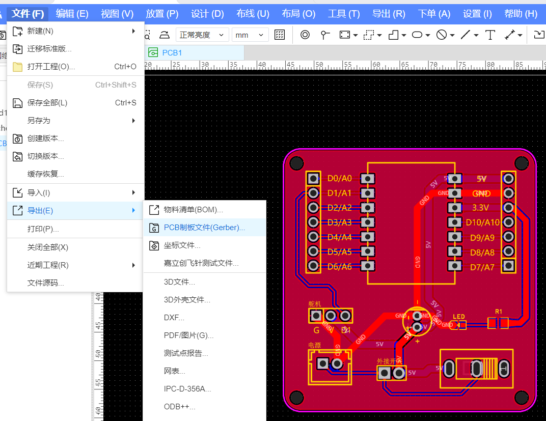
What I Learned:
Second Board: Single-layer PCB (Fabricated via CNC)
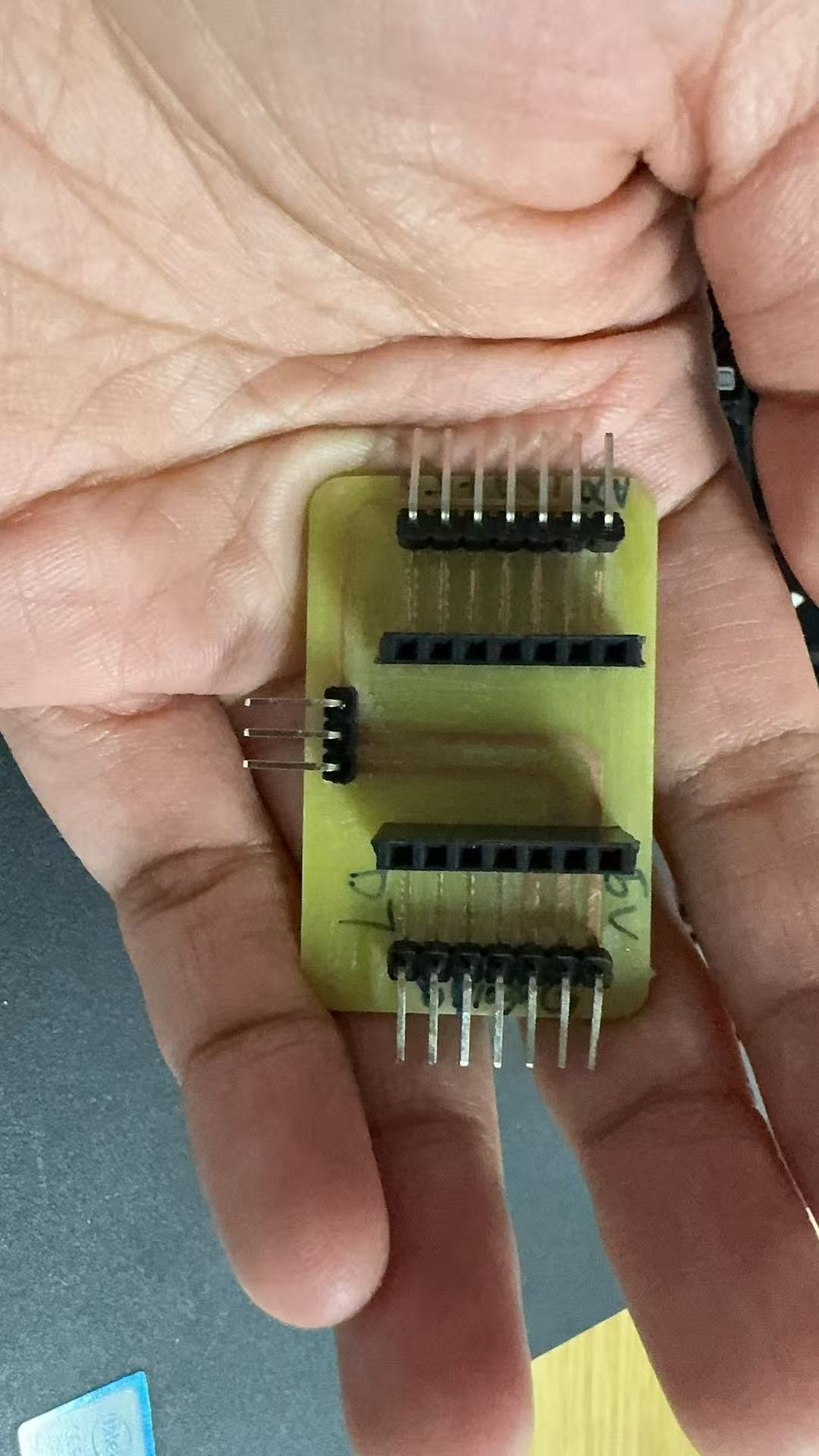
In addition to industrial prototyping, I also tried making a PCB myself. In the lab, I used the CNC module of the Snapmaker to engrave a single-layer PCB on a copper-clad board.
The expansion board actually used in the MechaSpider project was precisely this hand-crafted and soldered board.
6. Software Logic and Interactive Behavior
The MechaSpider program is written using the Arduino IDE and runs on the XIAO ESP32S3 microcontroller. The core goals of the software are:
Program Structure and Functional Division
Included Libraries:
#include <Adafruit_NeoPixel.h>
#include <Servo.h>
Module Initialization:
Main Loop (
loop()):Control Behavior Logic Flowchart
        ┌────────────┐
        │ Initialization │
        └────┬───────┘
             ↓
    ┌──────────────────┐
    │ Read Left/Right PIR │
    └────┬─────┬───────┘
         │     │
 Left detected  Right detected
         ↓     ↓
 ┌─────────┐ ┌─────────┐
 │ Move Right │ │ Move Left  │
 └────┬────┘ └────┬────┘
      ↓           ↓
 ┌──────────────┐
 │ Red Flashing │
 └──────────────┘
         ↑
         │
  No detection (default)
         ↓
 ┌────────────────────┐
 │ Blue Breathing + Stand │
 └────────────────────┘
Motion Design and Gait Analysis
Before I started writing code, I spent a significant amount of time understanding how my quadruped robot should move in a logical and efficient way.
Although the robot only uses 8 servo motors, each movement involves coordination between multiple servos. It’s not as simple as "just lifting one leg and walking."
Servo Numbering & Control Understanding
Based on the actual hardware wiring, I assigned the servo numbers as follows:
Servo ID Action Position Connected Pin S1 / S3 / S5 / S7 Leg Lifting (Up/Down) Knee joints of the four legs D0, D6, D5, D3 S2 / S4 / S6 / S8 Leg Swinging (Forward/Backward) Hip joints of the four legs D8, D7, D4, D1 Each leg is controlled by a combination of one lifting servo and one swinging servo. I also marked down the angle range for each servo to prevent it from exceeding its limit and getting stuck.
Motion Mapping and Gait Analysis Diagram
To better understand the robot’s walking behavior, I created an Excel diagram that includes:
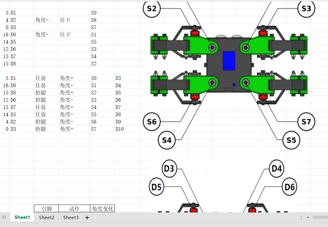
Each set of actions is organized into clear steps. For example:
Forward Gait Analysis
One complete “alternating leg pair forward gait” is achieved!
I experimented with different sequences and angles to find the most stable and jam-free gait combination.
Turning Gait Logic
Turning is relatively simpler. For example, the left-turn sequence is:
Repeating this sequence allows the robot to turn in place.
Avoidance Example: Person Approaching from Left → Move Right
Encapsulated Behavior Function:
void moveRight() {
  servo_3.write(60);  // Lift legs
  servo_7.write(60);
  delay(300);
  servo_4.write(40);  // Swing to the right
  servo_8.write(60);
  delay(300);
  servo_3.write(120); // Lower legs
  servo_7.write(120);
}
WS2812 RGB Lighting Logic
Controlled via the
Adafruit_NeoPixellibrary. The ring contains 8 LEDs. There are two main lighting modes:1. Blue Breathing Light (Idle Mode)
void blueBreathing() {
  for (int brightness = 0; brightness < 255; brightness++) {
    setAllLEDs(0, 0, brightness);
    delay(5);
  }
  for (int brightness = 255; brightness > 0; brightness--) {
    setAllLEDs(0, 0, brightness);
    delay(5);
  }
}
2. Red Flashing Light (Alert Mode)
void redFlash() {
  for (int i = 0; i < 5; i++) {
    setAllLEDs(255, 0, 0);
    delay(100);
    setAllLEDs(0, 0, 0);
    delay(100);
  }
}
7. Final Implementation Results
After multiple iterations across mechanical design, PCB fabrication, software development, and debugging, my final project MechaSpider successfully achieved all of its originally defined functional goals. It not only forms a closed-loop system of perception → reaction → expression, but also reaches a relatively stable and expandable state in both structural and electronic integration.
1. Directional Sensing: Accurate Left/Right Detection
Test Results:
2. Servo Movement: Coordinated Gait and Turning Actions
Observed Behavior:
3. LED Feedback: Visual State and Emotion Expression
Observed Performance:
4. Visual Design: Mechanical Spider Head + Quadruped Frame
Mechanical Performance:
5. Custom PCB: Stable Connections for All Modules
Electrical Performance: