Week 9: Input Devices
This week involves probing an input device's analog levels and digital signals as a group, and individually adding a sensor to a microcontroller board to measure something.
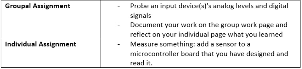
Group Assignment
Group assignment: Probe an input device’s analog levels and digital signals, document the work, and write a personal reflection on the individual page.
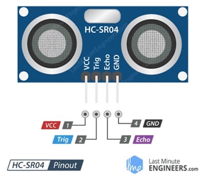
1. Connection Diagram of the HCSR04 Sensor
We used the HCSR04 ultrasonic sensor connected to an Arduino Uno board as follows:
- VCC → 5V
- GND → GND
- TRIG → Pin 9
- ECHO → Pin 10
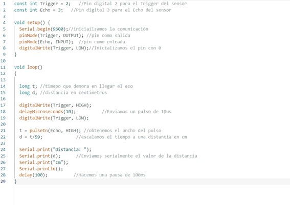
2. Code for Data Acquisition
The following Arduino code measures distance using the sensor and prints the results to the serial monitor:
#define TRIG_PIN 9
#define ECHO_PIN 10

void setup() {
  Serial.begin(9600);
  pinMode(TRIG_PIN, OUTPUT);
  pinMode(ECHO_PIN, INPUT);
}

void loop() {
  digitalWrite(TRIG_PIN, LOW);
  delayMicroseconds(2);
  digitalWrite(TRIG_PIN, HIGH);
  delayMicroseconds(10);
  digitalWrite(TRIG_PIN, LOW);

  long duration = pulseIn(ECHO_PIN, HIGH);
  float distance = duration * 0.034 / 2;

  Serial.print("Distance: ");
  Serial.print(distance);
  Serial.println(" cm");
  delay(500);
}
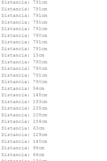
3. Measured Data
We placed different objects at various distances in front of the sensor and recorded the measurements. The readings were consistent, with minimal error at short distances.
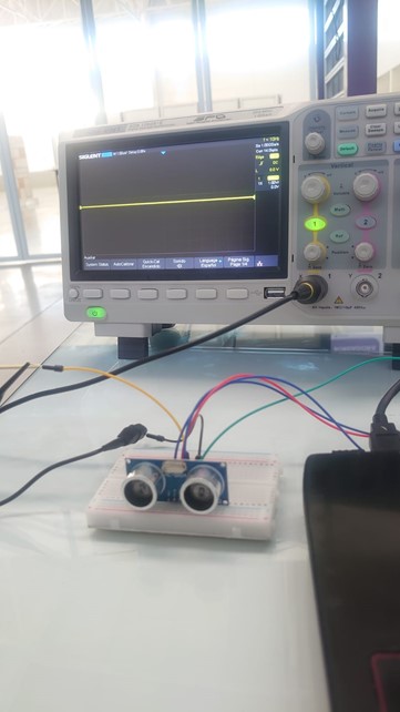
4. Oscilloscope Visualization
We connected the ECHO pin to the oscilloscope to observe the digital signals generated by the sensor. This allowed us to analyze the pulses produced for each measurement.
5. Test Video
We recorded a short video showing the full setup and real-time signal output:
Group Reflection
This assignment helped us understand how sensors convert physical phenomena into digital data and how to visualize these signals using an oscilloscope. Team collaboration was key to sharing ideas, troubleshooting, and completing the project effectively.
Individual Reflection
I gained a better understanding of how to capture and interpret digital signals and how sensor data can be processed in physical computing projects. I also learned the importance of sensor response time in accurate measurements.
Individual Assignment
Objective
The primary objective of this individual assignment is to implement a real-world measurement using a sensor interfaced with a custom-designed microcontroller board. For this, the VL53L1X sensor was used.
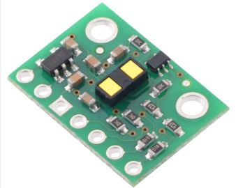
Sensor Used: VL53L1X
The VL53L1X is a state-of-the-art time-of-flight (ToF) distance sensor. It has an ultra-small package, offers accurate measurements regardless of the reflective surface, with a measurement range of up to 4m.
Distance Sensor Applications
- Energy Saving: User detection on computers, laptops, and tablets
- Robotics: Obstacle detection
- Domotics: Hand detection, automated pipes
- Gesture detection in 1D
- Auto-focus systems in digital cameras
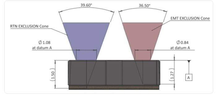
The specific task is to measure distances through a distance sensor using infrared. The principle of operation is based on emitting one infrared beam and receiving another. In this way, based on the time delay, the distance is calculated.
Sensor Connections
The connection diagram is very easy:
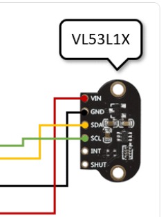
- VCC → 2.8V to 5V
- GND → GND
- SCL → I2C SCL pin (e.g., A5 on Arduino Uno)
- SDA → I2C SDA pin (e.g., A4 on Arduino Uno)
Data Reading
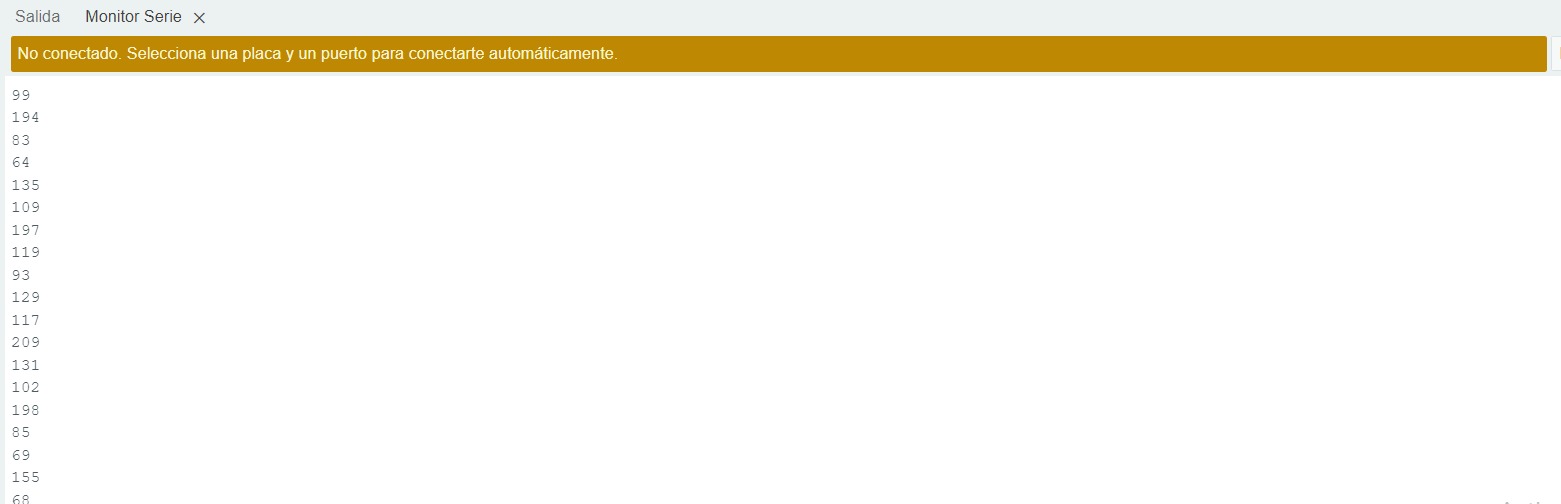
Video
In the video, you can see the experience with the use of the VL53L1X distance sensor:
Final Conclusions
In this week dedicated to input devices, we were able to understand the operating logic of sensors as devices that capture physical phenomena of the environment and then translate them into digital data useful for embedded systems. Through group work with the HC-SR04 ultrasonic sensor and individual development with the VL53L1X distance sensor, it was possible to experiment practically with both sensor connections and programming for data capture and visualization.
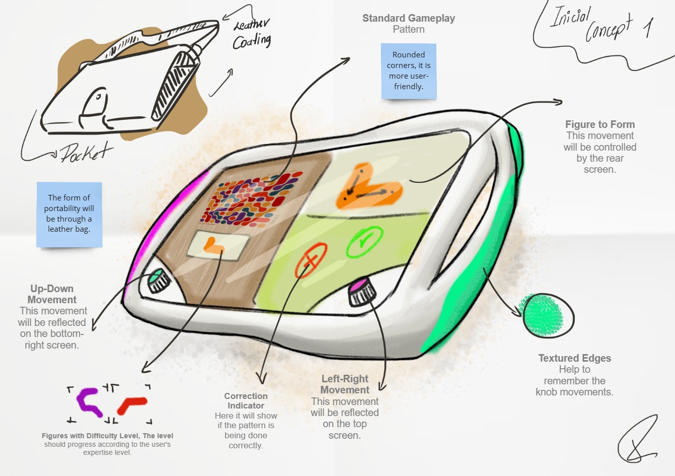
In this way, the input device used for this week's practice could be a useful resource for solving part of the interactions of the project “Interactive Ludic Device as an Experiential Resource for the Elderly”.