Electronics Design
An electrical circuit is a set of interconnected elements or devices that are used for the transmission, distribution, and transformation of energy in electrical systems. It may include various passive elements such as resistors, capacitors, inductors, or complex devices connected through conductors.
Group Assignment
1. Circuit Identification
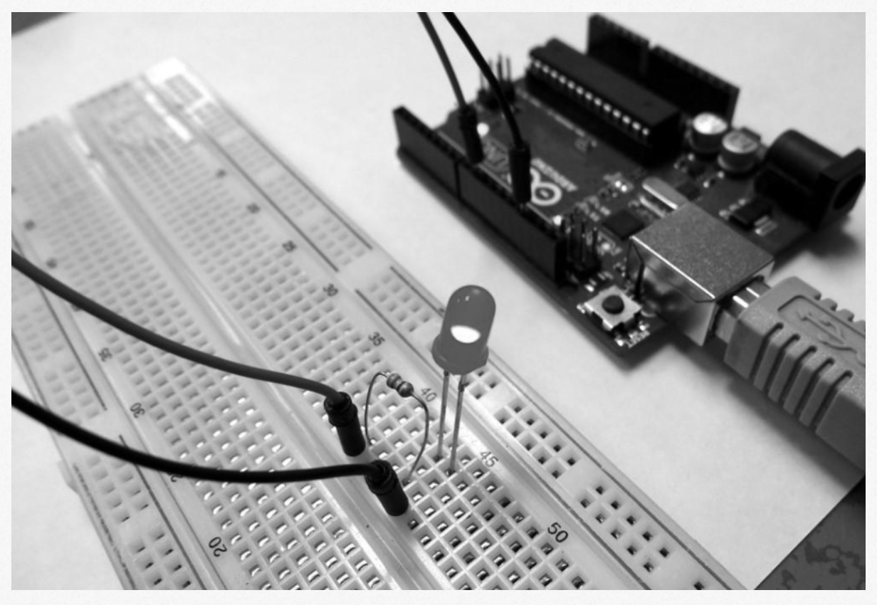
We analyzed a basic circuit using an Arduino UNO, a red LED, a resistor, and a breadboard. The LED was observed to be ON, confirming that the circuit was correctly powered and functional.
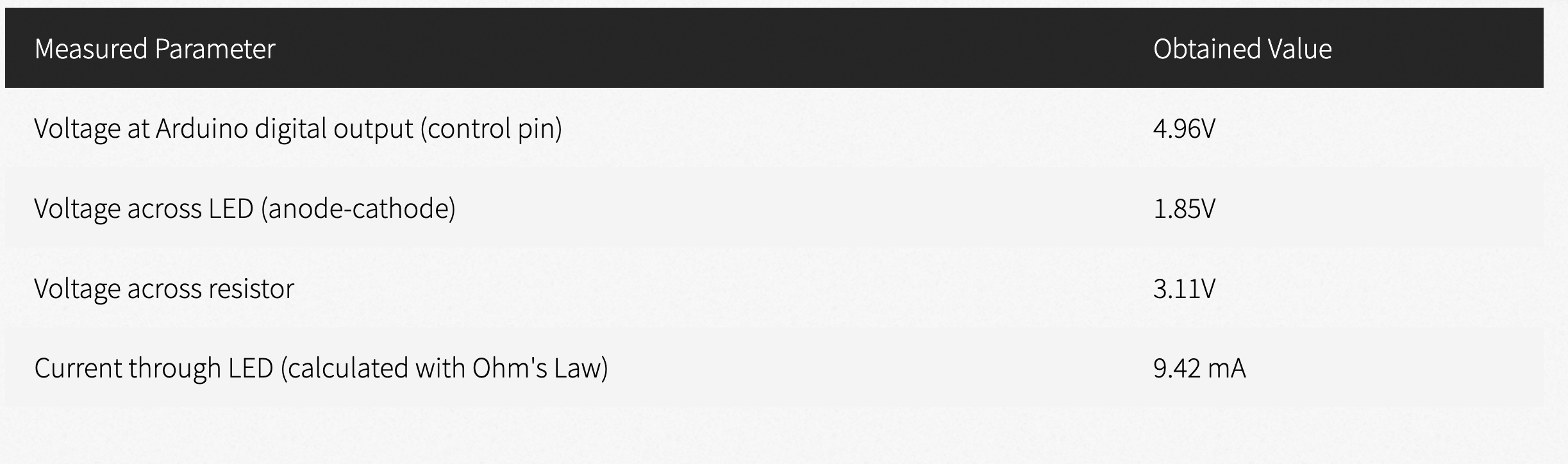
2. Measurement Results
3. Analysis of Results
- The measured voltage at the Arduino output confirms the microcontroller is providing a 5V signal, verifying the digital configuration.
- The voltage drop across the LED is around 1.85V, which is typical for red LEDs.
- The calculated current using Ohm’s Law I=V/R with R=330Ω is 9.42 mA, which is within the safe range for the LED.
- The LED remained ON without variations, indicating that no blinking code was executed in the Arduino.
Experiment Objective
The goal is to use the oscilloscope to visualize the PWM signal generated by Arduino. This demonstrates how the duty cycle of the signal changes over time, affecting the LED brightness.
Tools Used
- Arduino Uno → Generates the PWM signal on pin 6.
- Oscilloscope → Allows us to observe the signal and verify its variation.
- Connection wires → To connect the oscilloscope to the circuit.
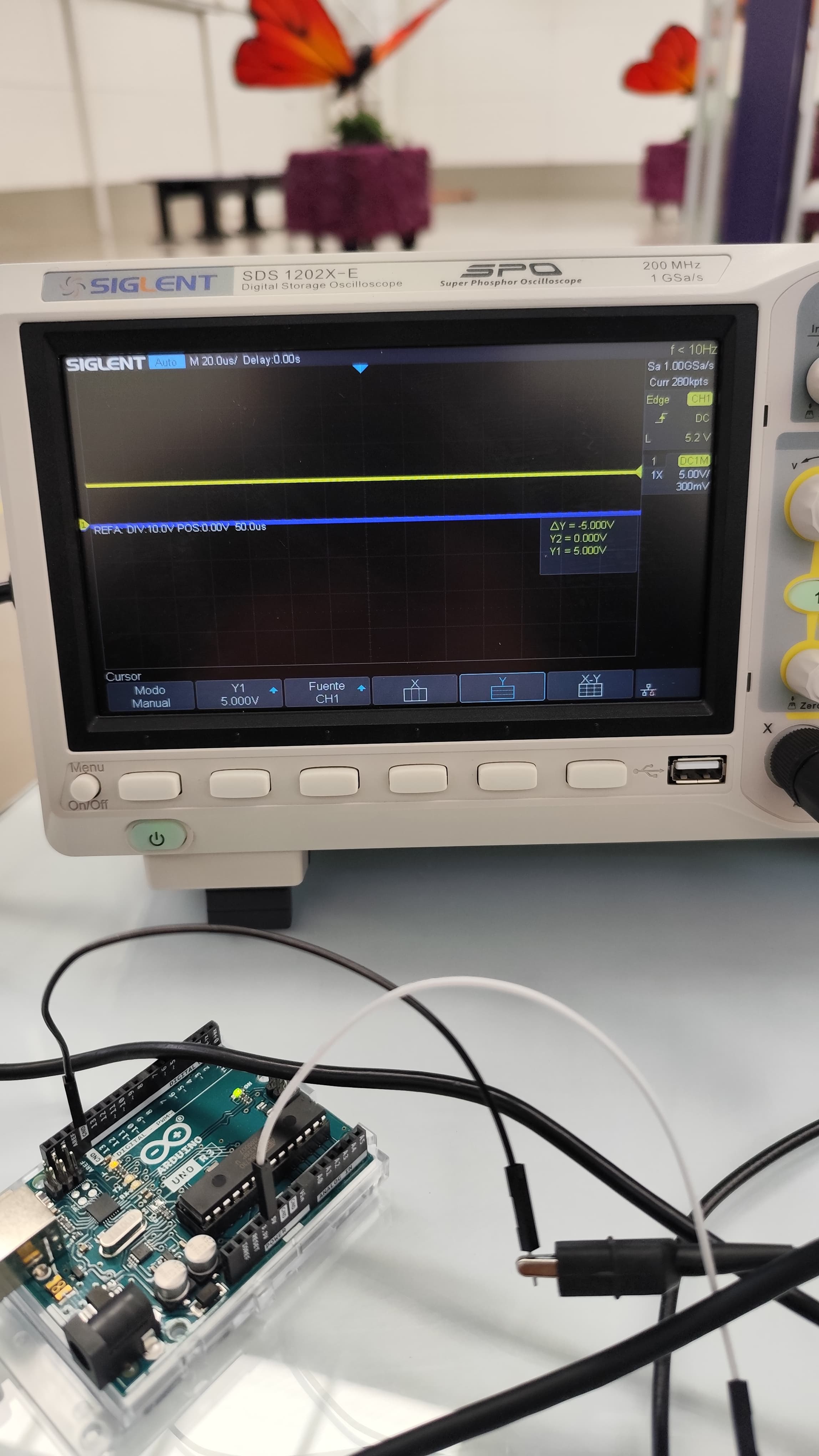
The images show an experiment using an Arduino Uno and a Siglent SDS 1202X-E oscilloscope to observe the PWM signal generated by the microcontroller.
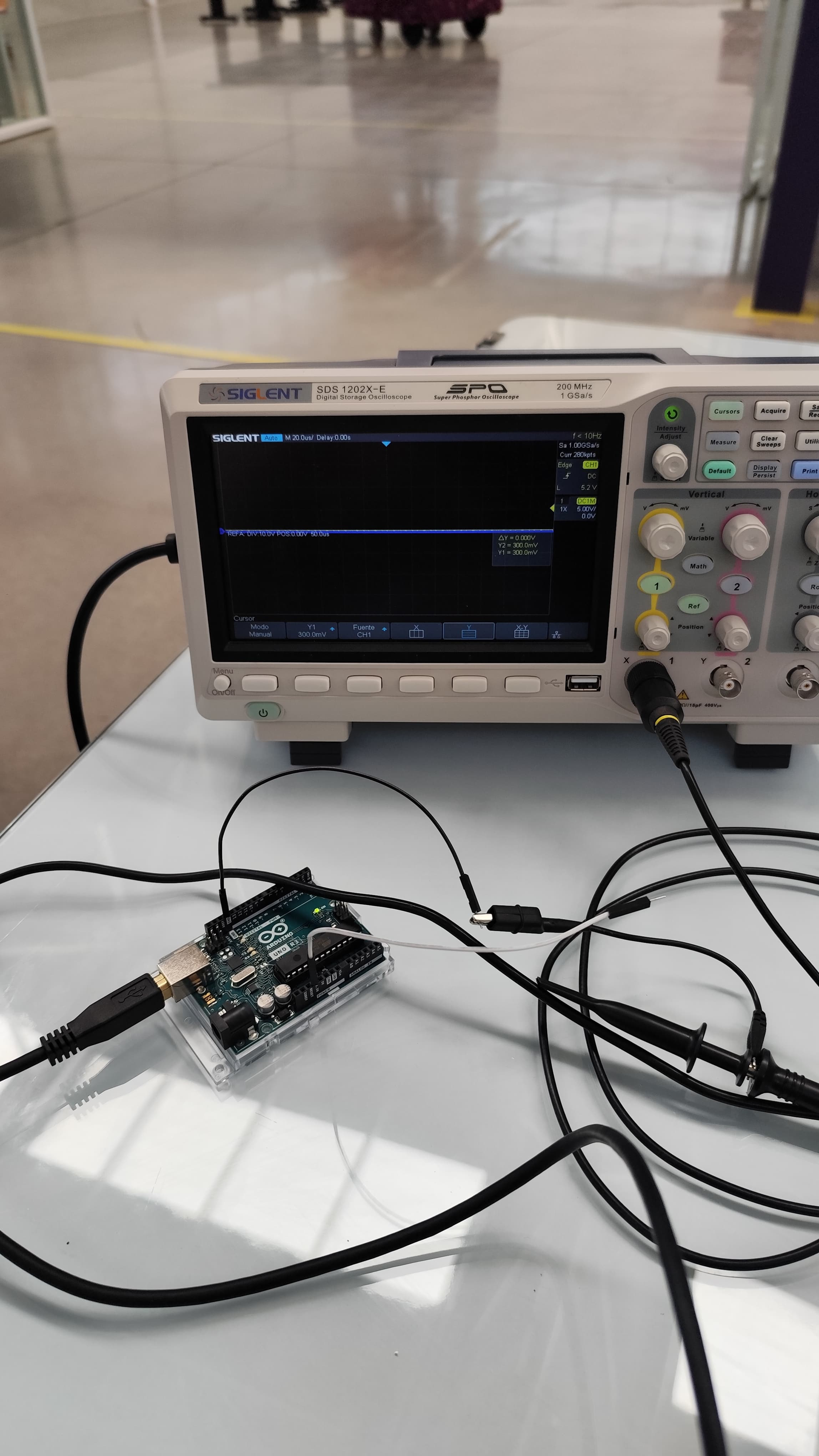
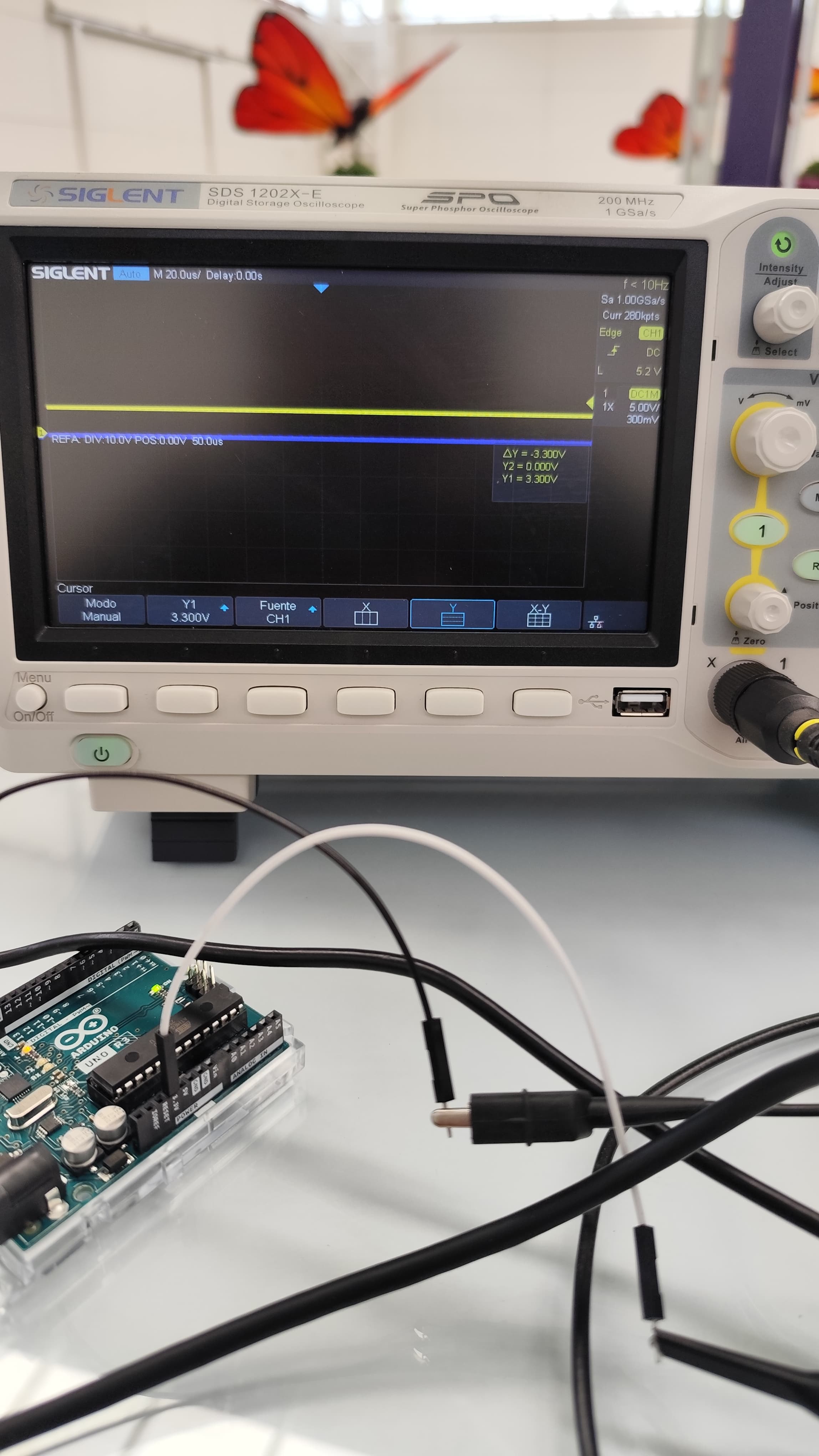
The oscilloscope displays a flat line at 3.3V, indicating that the measured pin is in a constant HIGH state (no PWM modulation visible yet).
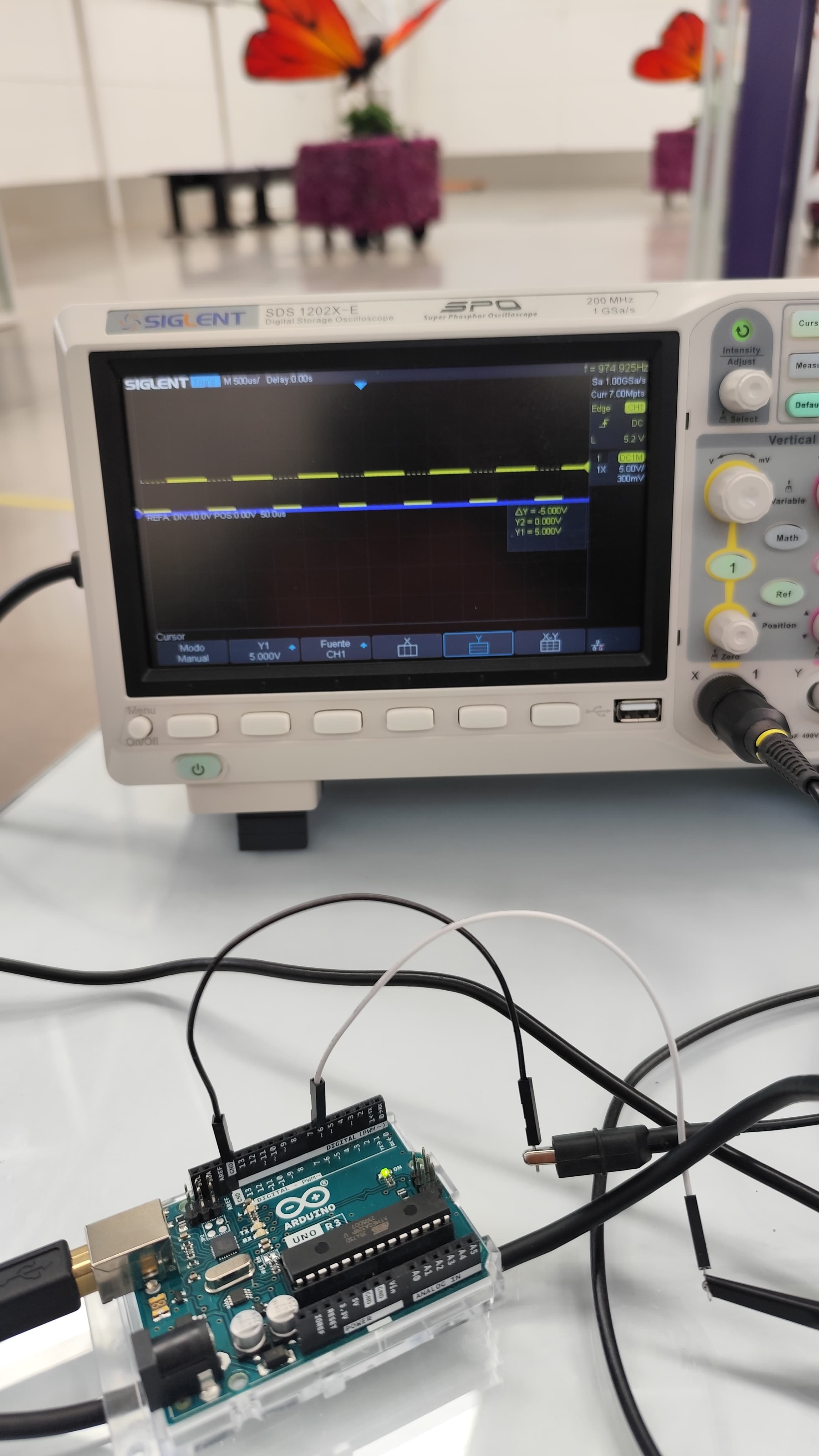
A pulsed (PWM) signal appears, with transitions between 0V and 5V. This confirms that Arduino is correctly generating the PWM signal.
Code Explanation
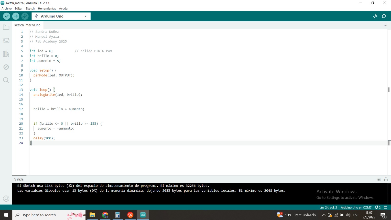
The Arduino code implements a progressive fading effect on an LED connected to pin 6 using PWM (Pulse Width Modulation).
Variables:
- led = 6; → Defines pin 6 as the LED output.
- brillo = 0; → Stores the LED brightness level (PWM value from 0 to 255).
- aumento = 5; → Defines how much the brightness increases or decreases in each iteration.
Initial Setup (setup):
pinMode(led, OUTPUT); → Configures pin 6 as an output.
Main Loop (loop):
- analogWrite(led, brillo); → Sends a PWM signal to the LED.
- brillo = brillo + aumento; → Increases or decreases brightness.
- If the brightness reaches 0 or 255, the aumento direction is reversed.
- delay(100); → Waits 100 ms before the next update.
Expected Behavior
The LED gradually increases in brightness until it reaches the maximum (255). Then, it gradually dims until it reaches 0. This cycle repeats indefinitely.
Arduino Code
Below is the Arduino code that implements the fading effect:
// Sandra Nuñez
// Manuel Ayala
// Fab Academy 2025

int led = 6;           // salida PIN 6 PWM
int brillo = 0;
int aumento = 5;

void setup() {
  pinMode(led, OUTPUT);
}

void loop() {
  analogWrite(led, brillo);

  brillo = brillo + aumento;

  if (brillo <= 0 || brillo >= 255) {
    aumento = -aumento;
  }
  delay(100);
}
4. Additional Observations
- No voltage fluctuations were detected in the circuit power supply.
- The LED is correctly oriented (anode connected to the Arduino output pin, cathode to the resistor).
- To further analyze the circuit, the Arduino code could be modified to make the LED blink and observe the waveform using an oscilloscope.
5. Conclusion
The circuit functions correctly based on the performed measurements. The LED receives the appropriate voltage, and the current remains within the recommended limits. Further testing could involve programming variations in the Arduino output signal and using an oscilloscope to visualize the waveform.
Individual Assignment
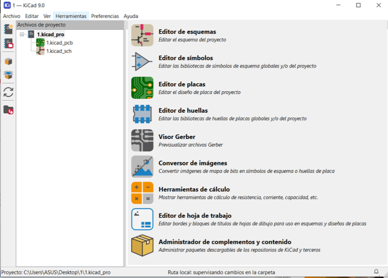
Use of KiCad
KiCad is a free software package for the automation of electronic design. It seeks to add new functions, which has made it possible to obtain a tool with sufficient features to deal with increasingly complex electronic systems.
Ki Cad is a free electronic design automation (EDA) software used to design electronic circuit schematics and convert them to printed circuit boards (PCBs). It is a software suite that facilitates the design and simulation of electronic hardware for PCB manufacturing.
1. Using KiCad Program
KiCad is an open-source program used to make electronic schematics and PCB boards.
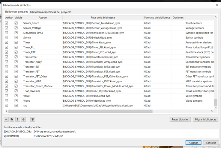
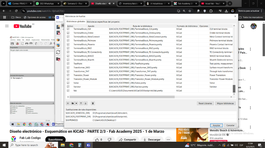
2. Downloading the FAB Academy Library
I downloaded the FAB Academy library that includes the components used in the certification, both the symbols and the footprints.
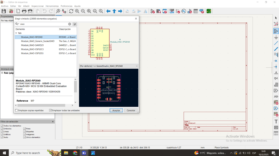
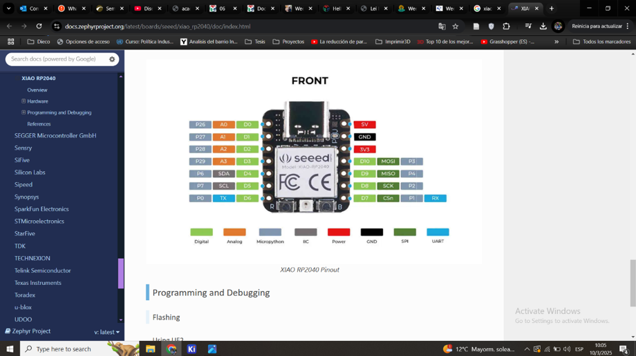
3. Using a XIAO 2040 Module
For this practice, we will use a XIAO 2040 module.
4. Features of XIAO 2040
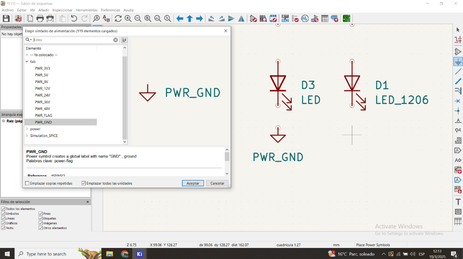
5. Electronic Elements Used
We will use 3 LEDs with their resistors, 1 push button, and a socket to connect a servomotor for this practice.
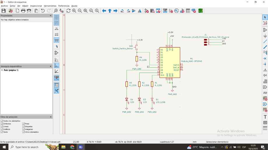
6. Verification of Schematic
Verification that there are no schematic errors.
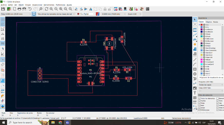
7. Arrangement of Electronics
Arrangement of the electronics so that the tracks are not crossed.
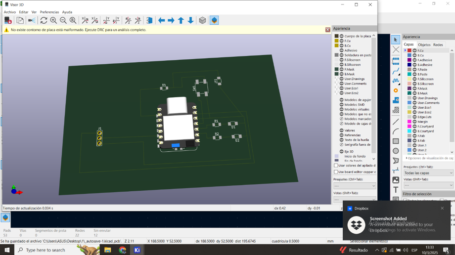
8. 3D Representation
Final Conclusions
This week's work focused on electronic design, combining theoretical understanding with reflection on practical application. In the group task, we analyzed a microcontroller-based circuit and performed electrical measurements to verify its functionality. The individual task consisted of designing a development board with KiCad, generating Gerber files, and simulating the circuit before fabrication.