10. Output devices
Group assignment:
Measure the power consumption of an output device. Document your work on the group work page and reflect on your individual page what you learned.
Individual assignment:
Add an output device to a microcontroller board you’ve designed and program it to do something. Learning outcomes
Group assignment:
For the Week 10 group assignment on output devices, we worked together to measure the power consumption of a servo motor using a custom PCB and a bench power supply. We programmed an MG90S servo motor with a sweep code in the Arduino IDE, connected it to the PCB, and powered the setup with the supply set at 5V and a maximum current of 0.5A. By observing the current drawn while the servo was sweeping, we found that the servo consumed up to ~0.3A, resulting in a maximum power usage of about 1.5W. This exercise helped me understand how to practically measure and calculate the power consumption of electronic components, which is crucial for designing efficient and reliable circuits. Overall, I learned how to set up the test, interpret the readings, and apply this knowledge to optimize power usage in my own projects
Individual Assignment
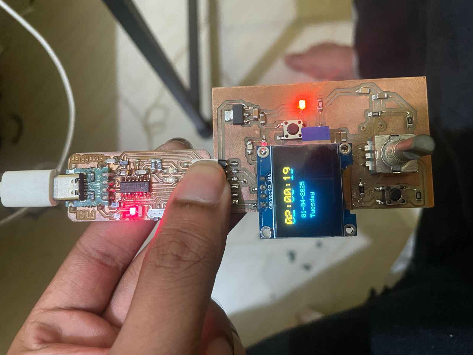
For this week, I chose to work with an SSD1306 OLED display as my output device. OLEDs are compact, energy-efficient, and provide crisp, high-contrast text and graphics, making them ideal for embedded projects like timers and clocks. I also used a rotary encoder for user input, allowing mode selection and value adjustment.
This PCB is a redesign from my Input Devices Week, where I initially tested the rotary encoder. For Output Week, I added connections and support for the OLED display, improving the board’s versatility for my final project
I tried to use the autorouter to the PCB design . There was some issues . It didnot work so i did the routing manually .

nothing worked

This is the Final Circuit Diagram that i routed manualy .

Then i have Uploaded to Gerber2Png and used Doubleside to Gernerate the Png files Required for milling .

added capacitors to rotary encoders as my instructor instructed . I added capacitors to the A and B pins of the rotary encoder to help filter out noise and prevent false readings. When you turn the encoder, the mechanical contacts inside can create tiny, fast spikes called "bounces" that might confuse the microcontroller and cause it to count incorrectly. The capacitors smooth out these spikes, so each step or click of the encoder is counted accurately and the readings are much more stable.

The below image is my Final circuit diagram . .


I have milled the PCb then i Realized that the Led is not connected Properly and then i found the connections are wrong and then i used a heat Gun to De solder it . It was a mistake . As the Heat Gun burned my led . I Told my instructor about this and he told there is a different way on how to use with LEDS .

The below image is the heated led where the top portion of the led has burned Off .

How to check the Pcb before connecting to your Laptop?
For that you could use the help of a power supply where the input voltage and current are set . for me the Input volatge was 5v and the ampere was set to 0.1 Ampere in channel 1.
Steps > choose the chanel > > Set the current and the voltage >connect the Probe accordingly the Red to the vcc and then black probe to the Ground > click the output .


If the current delivered is constant and if there is no over current drawn you could say the circuit is not short . If the circuit is short it will try to withdraw over current and you may see something like cc. (since the current is limited in the power supply as we have set it already it wont be a problem ). which means the circuit is short and you should check the connections . if it is short then connected to laptop . it may damage your laptop driver .


i tested the normal encoder codes from the last week . it was not working .


OLED DISPLAY .
OLED, or Organic Light-Emitting Diode, display is a type of electronic visual display technology that uses organic compounds to emit light when an electric current is applied. Unlike traditional LCD (Liquid Crystal Display) screens, which require a backlight to illuminate pixels, OLED displays are self-emissive. This means that each individual pixel in an OLED display emits its own light, allowing for deep blacks, high contrast ratios, and vibrant colors. OLED technology is known for its advantages, including faster response times, wider viewing angles, and reduced power consumption compared to some other display technologies.
| Step | Description |
|---|---|
| 1. Install Libraries | Install the Adafruit_GFX and Adafruit_SSD1306 libraries via the Arduino Library Manager. These libraries simplify drawing graphics and interfacing with SSD1306-based OLEDs. |
| 2. Hardware Connections | Connect the OLED's SDA and SCL pins to GPIO 21 and 22 of the ESP32, respectively. Ensure proper power connections (3.3V and GND). |
| 3. Initialize Display | Use display.begin(SSD1306_I2C_ADDRESS, SDA, SCL) in your setup code to initialize the display with its I2C address (commonly 0x3C). |
| 4. Clear and Setup Screen | Use display.clearDisplay() to clear the screen before drawing and display.display() to update the content on the OLED. |
| 5. Draw Graphics/Text | Utilize functions like display.setTextSize(), display.setTextColor(), and display.setCursor() to add text or shapes. For example, draw a rectangle using display.drawRect(x, y, width, height, color). |
| 6. Display Dynamic Data | Update content dynamically by clearing the screen and rewriting data in a loop. For instance, use a timer to fetch real-time data like time from an NTP server. |
| 7. Optimize Power Consumption | Turn off the display when idle using display.ssd1306_command(SSD1306_DISPLAYOFF) to save power in battery-powered applications. |
I2C
The SSD1306 OLED is connected via I2C, using GPIO21 (SDA) and GPIO22 (SCL) on the ESP32. I2C is a two-wire protocol that allows multiple devices to share the same bus. The OLED’s address is set to 0x3C. In the code, Wire.begin(21, 22); initializes the I2C communication, and the display library handles all further interactions.

#include <Wire.h>
#include <Adafruit_GFX.h>
#include <Adafruit_SSD1306.h>
#define SCREEN_WIDTH 128
#define SCREEN_HEIGHT 64
#define OLED_RESET -1
#define SDA_PIN 21
#define SCL_PIN 22
Adafruit_SSD1306 display(SCREEN_WIDTH, SCREEN_HEIGHT, &Wire, OLED_RESET);
void setup() {
Serial.begin(115200);
// Initialize I2C with specific pins
Wire.begin(SDA_PIN, SCL_PIN);
if(!display.begin(SSD1306_SWITCHCAPVCC, 0x3C)) {
Serial.println(F("SSD1306 allocation failed"));
for(;;);
}
// Clear the buffer
display.clearDisplay();
// Set text properties
display.setTextSize(2);
display.setTextColor(WHITE);
display.setCursor(25, 25);
// Display "Hello"
display.println("Hello");
// Show on the display
display.display();
}
void loop() {
// Your main code can go here
}
Prompt used:(more in pdf )
“Write Arduino code to display the current time from an NTP server on an SSD1306 OLED using ESP32, with I2C on pins 21 and 22.”
Code Explanation: The code initializes the OLED and connects to WiFi, then fetches the time from an NTP server and displays it. To change the time zone (for example, to display the time in another country), simply adjust the gmtOffset_sec variable in the code to match the desired time zone offset
Displaying Time Using NTP Servers
| Step | Description |
|---|---|
| Include Libraries | Add WiFi, NTPClient, and Adafruit_SSD1306 libraries to your project |
| Initialize WiFi | Connect to a WiFi network using your SSID and password |
| Configure NTP Client | Set up NTPClient with a pool server (e.g., "pool.ntp.org") |
| Fetch Time | Use NTPClient's update() and getFormattedTime() functions |
| Display on OLED | Write the fetched time to the OLED display using Adafruit_SSD1306 functions |
| Periodic Updates | Implement a timer to update the displayed time every minute |
|

CONCLUSION
Throughout this project, I gained valuable hands-on experience in PCB design, component handling, and troubleshooting. I learned important lessons about proper desoldering techniques, especially for sensitive components like LEDs. The implementation of the OLED display and rotary encoders has enhanced my understanding of integrating different electronic components and programming them effectively.