3. Computer controlled cutting
Tasks for this Week:
Individual Assignment:
- Cut something on the vinyl cutter
- Design, laser cut, and document a parametric construction kit
Group Assignment:
- Characterize your laser cutter's focus, power, speed, rate, kerf, joint clearance, and types
GROUP ASSIGNMNENT
This week, as a group, we focused on computer-controlled cutting using the Trotec Speedy 400 laser cutter. We began by reviewing lab safety protocols, including the use of PPE, emergency procedures, and safe handling of all equipment.
Together, we experimented with different laser parameters-such as power, speed, and focus-to understand their impact on cutting quality. We measured the kerf for various materials (cardboard, wood, and acrylic) to ensure our designs would fit together accurately.
We also explored a variety of laser-cut joints, including finger joints, snap-fits, and living hinges, and discussed how to adjust clearances for a proper fit. As a team, we practiced parametric modeling in Fusion 360, which allowed us to quickly adapt our designs for different material thicknesses and kerf values.
Overall, this week strengthened our group’s skills in safe machine operation, precise measurement, collaborative problem-solving, and adaptable design for digital fabrication.

Trying Out Designs for Vinyl Cutter
This week focused on learning how to operate laser cutters and vinyl cutters. We used laser cutters to engrave and cut different shapes on various materials like cardboard, wood, and acrylic.
Inkscape is the tool we used for vector modeling designs.
Different colors are assigned to different functions. Red indicates cutting, while black indicates engraving.
When using the vinyl printer, we need to vectorize the file and define paths before uploading.
We could design according to our ideas. I designed a Transformers logo using Inkscape to vectorize the image. The link to the transformers that i downloaded is listed below.
To vinyl print an image, ensure it's of standard quality. Go to Path and select Trace Bitmap, and Inkscape will handle the vectorization process.

This is the machine that we use for vinyl printing . Roland To operate the vinyl cutting machine, turn it on using the blue button located at the bottom-right of the control panel.
The machine will prompt you to select the material type—either roll or piece. For a piece, the machine will measure its exact dimensions. For a roll, it will only measure the width. Load material through the back, similar to a printer. The presser foot can be lifted up and down using a lever for feeding the vinyl paper.
Make sure the two wheels are within the white striped areas on the machine to avoid a "Bad Position" error.
From Roland user manual
The values that we set for the vinyl cutting are as follow the power is 100 and speed is 2

this is the basic image of the components.

MODS
At our fablab, we use ModsCE (Mods Community Edition) as the main software tool to control both the vinyl cutter and the PCB milling machine. ModsCE is an open-source, cross-platform tool that was originally developed at MIT’s Center for Bits and Atoms (CBA) by Neil. The main idea behind ModsCE is to provide a modular, browser-based interface that can control a wide range of digital fabrication machines using a single, unified workflow.
ModsCE works by connecting different modules-each representing a step in the fabrication process-so you can customize or automate tasks like file preparation, toolpath generation, and machine control. This flexibility makes it especially useful for fablabs, where multiple types of machines and workflows are common.
The software is actively maintained by the global Fab Lab community, and you can find more information or access the tool at the following links:
ModsCE GitLab repository vinyl printing is done using Fablab Mods . Open the Mods and run the the bash script.
After mods opens on the browser right click to select programs

Then right-click on the page, navigate to "Programs," select "Open Program," and choose "GX-GS 24 Vinyl Cutters - Cut."

input the svg file that you want to vinyl cut.
- Select the origin point based on how you positioned the vinyl in the cutter.
- Set the DPI to "1000".(When using SVG files in ModsCE, setting the DPI (dots per inch) is necessary to ensure accurate scaling between digital designs and physical output, even though SVG is a vector format.)
- Click the "calculate" button.
- Check your image path in the "vectorize" box. Then click "open socket" followed by "send file to device" to start cutting.

To transfer the design, apply a layer of transfer tapee on top of the remaining design. Make sure to firmly rub the design onto the transfer paper.
Use tweezers and a handblade to carefully remove the excess vinyl sticker material


Remove the transfer tape by taking it to the area where you want to place the vinyl and rubbing it firmly so that the vinyl sticks to the laptop .

This is what i plotted .
LASER CUTTING
Laser cutting is a precise manufacturing process that uses a focused laser beam to cut materials. For our lab work, we used an Trotec cutter which can both cut and engrave various materials like wood, acrylic, and cardboard. The key parameters we need to consider when laser cutting are power, speed, frequency, and focus distance.

The laser cutting process involves several key steps, beginning with creating and programming the cutting pattern. Once programmed, the machine executes the cutting sequence.
- Laser generation: A resonator converts power supply energy into a laser beam.
- Laser amplification: Two mirrors at the head's ends intensify the laser beam as it passes through an amplifying medium.
- Laser direction and focus: Either fiber optic cables or focusing head mirrors guide the laser beam. A lens then concentrates the beam's energy to achieve cutting power.
- Gas supply: The nozzle releases gas to clear molten material from the cut line (kerf).
- Cutting: The focused laser beam melts and vaporizes material while the cutting head moves along the programmed pattern, creating the kerf. Sometimes the material moves instead of the cutting head.
Types of laser used in our lab
- CO2 Lasers: These lasers cut non-metallic materials including wood, acrylic, plastic, fabric, leather, and paper. They can also cut metal when it has a special coating to prevent reflection.
- Fiber Laser Cutting: These high-efficiency lasers excel at cutting metals, including both ferrous metals like steel and non-ferrous metals like aluminum, copper, and brass.

- To start the machine, first turn on the power supply, then turn the knob to the right.
- Ensure the lid is closed during initialization.
- Position your material in the workspace, preferably at the upper left corner (origin point 0,0).
- Navigate the laser head using the arrow keys on the machine's interface. The up/down arrow keys marked with the "Z" symbol control the laser head's vertical movement along the z-axis.
- Proper z-axis setup is crucial for laser focus. Place the focus tool's gold lip (Focus key as in Image below) on the small ledge of the laser head, allowing it to float lightly. Adjust the bed height using the z-axis controls until the focus key just barely detaches from the laser head.
- To auto-focus the laser head, simultaneously press both the up and down arrow keys (marked with "Z") on the machine panel.

Software Setup
Trotec JobControl is laser software that prepares graphics and text for laser engraving or cutting. It receives print jobs from image editing software and arranges them on the laser cutter's bed.
- You can use the job center coordinates to position the laser head. The software offers complete customization of power, velocity, frequency, material type, and design placement.
- To begin, open the menu and select "Import from File" to load your design.
- Position your imported design by setting the origin coordinates.

- Choose your material from the list. For our test, we selected "cardboard".

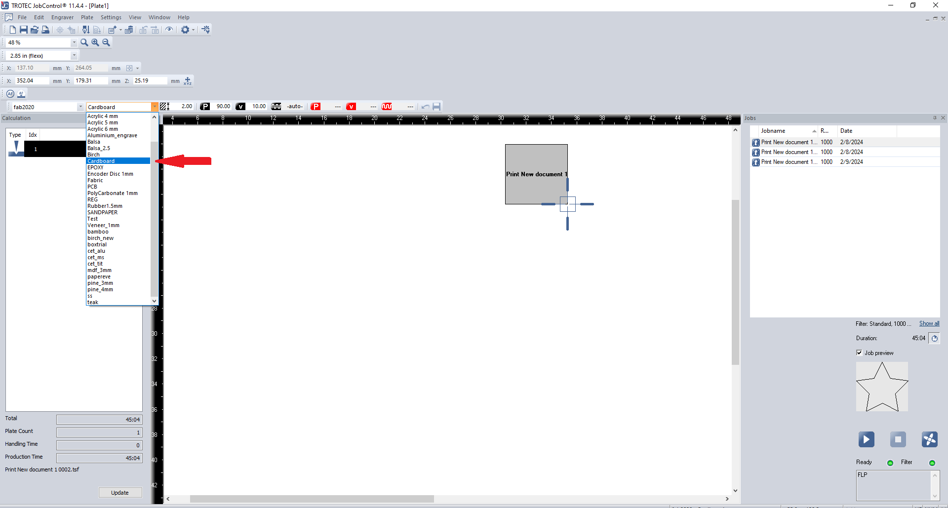
- Access the "material template" (or press "Ctrl + M") to set the processing parameters for each color in your design.
Click the play button at the bottom to start the job. The design will be engraved, or cut on your chosen material. If the material isn't cut properly, repeat the cutting process. If the joints don't fit correctly, adjust the kerf value and print again until you achieve the perfect result.
Parametric Construction kit
A parametric construction kit is a modular system where parts are designed with adjustable parameters, allowing for flexible and customizable assembly. Using laser cutting technology, we can create precise interlocking pieces that form various structures. The key advantage of parametric design is that dimensions and configurations can be easily modified to suit different needs while maintaining consistent assembly methods.

We use Fusion 360 for parametric designing. Below I will show how the design flow works:
Draw the shapes you want to laser cut, click on "Modify," and look for the parametric tab. From there, you can adjust all the parameters as needed.

This is how parameters tab look like

To change the parameters you could change here like this below where you could see as the parameters are adjusted the sizes are changed too .

Here the height is changed from 9 to 12 as the parameter has been adjusted .

Use the shortcut key 'E' for the extrude command. After extruding the joints to the desired thickness, arrange the pieces using the arrange option. You can find this under Sketch > Modify > Arrange. Enter your available cardboard size, and the software will automatically arrange the pieces to fit within those dimensions. select the plane before you are going to arrange .


Export the component as a DXF file by right-clicking on the arranged sketch and selecting the "Export as DXF" option.

Export the DXF file to Inkscape, then use Ctrl + P to print, which will send the file to JobControl for laser printing.
IN inkscape Set the Border line stroke to Red Colour and 0.1mm depth .And Remove if there is any Fill. USe CTRL + SHIFT + R to make the canvas .

First i cutted two parts to test whether the card peices are joining together .

the below things are what i made using the cardboard pieces . I made a tortoise with cardboard.

Reference Image .that i took as a reference . The final result is on the side.


CONCLUSION
In this lab session, I successfully learned about laser cutting technology and parametric design principles. Through hands-on experience with the Trotec laser cutter and Fusion 360 software, I gained practical skills in creating precise, customizable components. The combination of theoretical knowledge and practical application has provided me with a solid foundation for future projects involving laser cutting and parametric design.
FILES
PROMPT USED
https://fabacademy.org/2025/labs/kochi/students/abin-mathew/assignments/week03/ . This is the link to my week 3 of my fabacademy go through this and help me rewrite the documentation .These are some previous week 3 links for references . (add any accordingly )