Final Project#

Rough Sketch#

Overview#
- Upon graduation, you receive a certificate. But I wanted something more physical that could remain as a lasting memory.
Idea#
- A memorial trophy to remind you of Fab Academy 2025 @ Node Kannai
Features#
Basic Requirements#
- Easily recall what was done in the weekly assignments.
Basic Functions#
- The trophy part is made of acrylic, engraved with “Fab Academy 2025 @ Kannai” and the participant’s name using a laser.
- The base is equipped with an OLED display.
- The base is made using a 3D printer.
- Sliding the trophy part detaches it from the base, allowing maintenance of the circuit board.
- Pressing a switch causes the trophy to light up.
- The bottom of the base features a plywood puzzle piece branded with a QR code that links to the 2025 Kannai page.
Advanced Requirements#
- Personal Fab Academy
- Along with memories, it automatically generates new challenges to take on and creates a personal page for them.
- The Fab Trophy will function as your own Personal Fab Academy, continuously generating new assignments to boost your creativity.
- While the original Fab Academy provided weekly assignments with strict deadlines, the assignments in the Personal Fab Academy come with no submission deadline.
Note
The idea that constraints enhance creativity was proposed by Professor Teresa M. Amabile of Harvard Business School.
In her “Componential Theory of Creativity,” she states that creativity arises from the interaction of an individual’s abilities, motivation, and environmental factors.
Notably, it has been shown that when constraints are ** appropriately set, they can promote creative thinking.**
Advanced Functions#
- Pressing a switch generates a challenge by combining assignments using an LLM and pushes it to each participant’s designated page.
- The difficulty level can be changed using a rotary switch.
- When a new challenge is created, a notification appears on the OLED, and a QR code to the page is displayed.
- The trophy includes a hologram feature, and pressing the switch projects memories as a hologram.
- When all four trophies are collected, they combine into one.
System Integration#
system integration’s information is here
System Requirements for Basic Functions#
System Configuration for Basic Functions#

System Configuration for Advanced Functions#

Project Tasks#

| Project | Category | Task | Start Date | End Date | Days |
|---|---|---|---|---|---|
| Basic | Design | Design of trophy structure and slide mechanism | 2025-05-11 | 2025-05-13 | 2 |
| Basic | Design | Design of veneer QR puzzle | 2025-05-13 | 2025-05-14 | 1 |
| Basic | Fabrication | Acrylic cutting and engraving | 2025-05-14 | 2025-05-15 | 1 |
| Basic | Fabrication | 3D printing of the base | 2025-05-15 | 2025-05-16 | 1 |
| Basic | Fabrication | Veneer processing for QR code | 2025-05-16 | 2025-05-17 | 1 |
| Basic | Fabrication | Implementation of sliding mechanism | 2025-05-17 | 2025-05-18 | 1 |
| Basic | Electronics | Implementation of LED lighting circuit | 2025-05-18 | 2025-05-19 | 1 |
| Basic | Electronics | Display QR code for kannai page on OLED | 2025-05-19 | 2025-05-20 | 1 |
| Basic | Electronics | USB power wiring and testing | 2025-05-20 | 2025-05-21 | 1 |
| Advanced | Documentation | Basic system diagram and fabrication record | 2025-05-21 | 2025-05-22 | 1 |
| Advanced | LLM | Selection and build of LLM for XIAO ESP32S | 2025-05-22 | 2025-05-25 | 3 |
| Advanced | LLM | Implementation of prompt and difficulty settings for task generation | 2025-05-25 | 2025-05-26 | 1 |
| Advanced | LLM | Integration with GitLab (Push) | 2025-05-26 | 2025-05-27 | 1 |
| Advanced | LLM | OLED notification and GitLab QR code generation | 2025-05-27 | 2025-05-28 | 1 |
| Advanced | Hologram | Optimization of OLED and acrylic reflection | 2025-05-28 | 2025-05-31 | 3 |
| Advanced | Combination Mechanism | Design and adjustment of divided kannai structure | 2025-05-31 | 2025-06-01 | 1 |
| Advanced | Documentation | Documentation of LLM integration | 2025-06-01 | 2025-06-02 | 1 |
| Advanced | Video Production | Creation of presentation video | 2025-06-02 | 2025-06-05 | 3 |
BOM#
| Component / Material | Quantity | Supplier | Price |
|---|---|---|---|
| Seeed Studio XIAO ESP32S3 | 1 piece | Akizuki Denshi | 1,300JPY |
| VKLSVAN 0.96″ OLED Display (5 pieces) | 1 set | Amazon | 980JPY |
| 40-pin SMD Pin Header (2×20) | 1 piece | Akizuki Denshi | 80JPY |
| Potentiometer 5KΩB | 1 unit | Akizuki Denshi | 60JPY |
| Knob for small volume 20mm (with flange) ABS-15 | 1unit | Akizuki Denshi | 30JPY |
| Acrylic Sheet 450×300×2 mm (clear) | 1 sheet | Acry-ya.com | 959JPY |
| Paper Phenolic PCB FR-1 150×200×1.6 mm | 1 sheet | Yodobashi | 380JPY |
| Jumper Wire Set | 1 set | Amazon.co.jp | 699JPY |
| 1×40-pin SMD Female Header (2.54 mm pitch) | 1 pack (5 pcs) | Aitendo | ¥35 |
| LED(5988230107F,LED ORANGE CLEAR 1206 SMD) | 1 unit | Fab Cloud Inventory | 0.21USD |
| Resistors (RC1206FR-07499RL,499Ω) | 1 unit | Fab Cloud Inventory | 0.01USD |
| 3D-Printed Enclosure (ABS filament only) | Approx. 50g | Bambu Lab | 170JPY |
| Joystick RKJXV122400R | 1 unit | Akizuki Denshi | 190JPY |
Iteration 1: Implementing basic features#
Iter1-1. Modeling#
Create modeling with Fusion


Iter1-2. Laser cutting acrylic#
Iter1-3. Coloring the acrylic#

Iter1-4. Test connecter parameter#
In order to find the parameters that would allow for a proper connection between the acrylic and the base, we modeled the connection with different parameters, printed it out with a 3D printer, and tested to see if it would actually fit.
The parameter range is shown in the following image.
![]()
As a result of the actual connect, the joint clearance parameter was found to be 0.03 mm, which is appropriate.
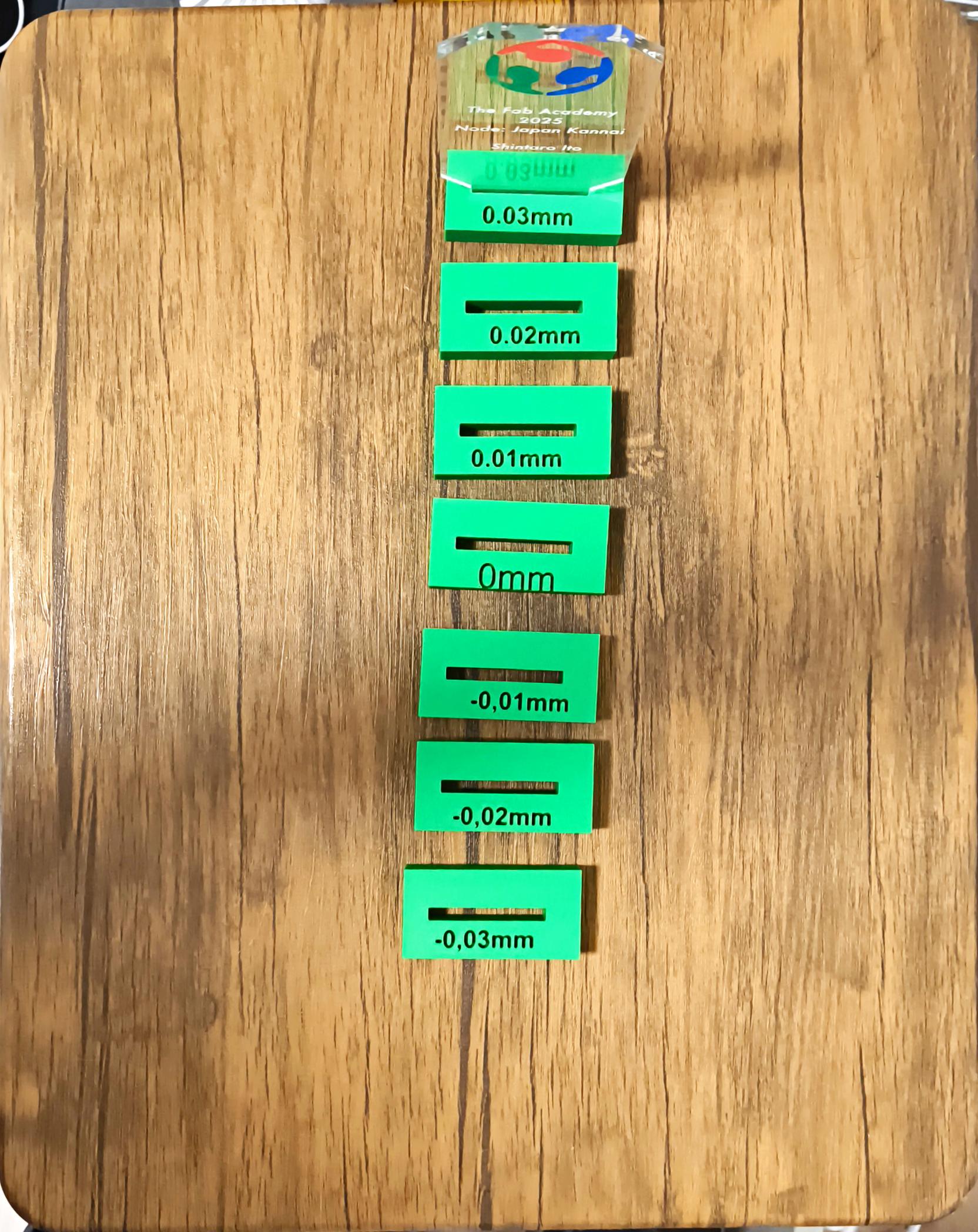
The clearances found in this test were reflected in the model parameters.

Iter1-5. how to 3d printing#
DL the stl file from fusion and create the data for printing in bambu studio.
- load the data. You can load the data by clicking the cube symbol on the left end of the toolbar above.
 Select “split to object” surrounded by a red square in the following image to separate the object.

- have the objects separated by “range all objects” be organized in an appropriate manner.

- select “cut” to break up complex objects. This will reduce overhangs and bridge distances and reduce the probability of spaghetti.
 In this case, we have set up the following image.

- select “range all obujects” again and organize the objects again.

- select “auto orient” to have the object placed in the most efficient orientation.

- use “support painting” to paint the inevitable overhangs.

- create a slice plate with “slice plate” in the upper right corner.
 If the slice plate is in good condition, you can print by selecting “print plate” at the top right corner.

3D Printer Printing Time Lapse
The following image shows the printed result.

Iter1-6. PCB design#
Create schematics and PCB.


Once the PCB design was complete, the exported PNG file was uploaded to Mods to create gcode data.


Drills are used to cut copper plates.
Soldering was done.

Iteration 2: Implementing advanced features & Reproduction#
Iter2-1. issue gemini api key#
- access Aistudio and issue API key.
aistudio

Iter2-2. issue a gitlab api token#
- Set up the following flow in gitlab.
- User Settings > Preferences > Access tokens > add new token
-
set up and issue TOKEN as shown in the image.

-
Please use the curl command to check if it is actually available.The following command will push test.md to the docs > personal fab academy directory of your project.
if you use this curl commands , you should change those parameters
- When using the curl command, please modify the following two parts to your own information.
- {your_pj_id} in the url, the id number can be found in the image below.

- header {yourtoken}. Enter the aforementioned api token.
- {your_pj_id} in the url, the id number can be found in the image below.
curl --request POST "https://gitlab.fabcloud.org/api/v4/projects/{your_pj_id}/repository/files/docs%2Fpersonal%20fab%20academy%2Ftest.md" \
--header "PRIVATE-TOKEN:{yourtoken}" \
--header "Content-Type: application/json" \
--data '{
  "branch": "main",
  "content": "# Test\nThis is a test file created via GitLab API.",
  "commit_message": "Initial commit of test.md"
}'
Iter2-3. Generate QR code and display on OLED#
For QR code generation, I was allowed to use QRcode created by ricmoo.
The implementation code is as follows.
    [env:seeed_xiao_esp32s3]
    platform = espressif32
    board = seeed_xiao_esp32s3
    framework = arduino
    upload_speed = 115200
    monitor_speed = 115200
    upload_port = /your/port
    board_build.partitions = huge_app.csv
    build_flags =
      -DARDUINO_USB_MODE=1
      -DARDUINO_USB_CDC_ON_BOOT=1
    lib_deps =
      bblanchon/ArduinoJson @^6.21.2
      adafruit/Adafruit GFX Library@^1.12.1
      adafruit/Adafruit SSD1306@^2.5.14
      https://github.com/ricmoo/QRCode.git
    lib_ldf_mode = deep
  #pragma once
  #include <Adafruit_SSD1306.h>
  #include <qrcode.h>

  class OLEDdisplay
  {
  public:
      OLEDdisplay(uint8_t width, uint8_t height);
      void begin();
      void showMessage(const String &text, uint8_t textSize = 1);
      void clear();
      void showQRCode(const String &text, uint8_t version = 3, uint8_t scale = 2);

  private:
      Adafruit_SSD1306 display;
      String currentText;
  };
#include "OLEDdisplay.h"
OLEDdisplay::OLEDdisplay(uint8_t width, uint8_t height)
    : display(width, height, &Wire, -1), currentText("") {}

void OLEDdisplay::begin()
{
    Serial.println("OLEDdisplay code reading start");
    if (!display.begin(SSD1306_SWITCHCAPVCC, 0x3C))
    {
        Serial.println("display Initialization Failure. So I freeze...");
        while (true)
            ;
    }
    display.clearDisplay();
    display.display();
}

void OLEDdisplay::showMessage(const String &text, uint8_t textSize)
{
    if (text != currentText)
    {
        currentText = text;
        display.clearDisplay();
        display.setTextSize(textSize);
        display.setTextColor(SSD1306_WHITE);
        display.setCursor(5, 5);
        display.println(text);
        display.display();
    }
}

void OLEDdisplay::clear()
{
    display.clearDisplay();
    display.display();
}

void OLEDdisplay::showQRCode(const String &text, uint8_t version, uint8_t scale)
{
    QRCode qrcode;
    uint8_t qrcodeData[qrcode_getBufferSize(version)];
    qrcode_initText(&qrcode, qrcodeData, version, ECC_LOW, text.c_str());

    int offset_x = (display.width() - qrcode.size * scale) / 2;
    int offset_y = (display.height() - qrcode.size * scale) / 2;

    display.clearDisplay();
    for (uint8_t y = 0; y < qrcode.size; y++)
    {
        for (uint8_t x = 0; x < qrcode.size; x++)
        {
            if (qrcode_getModule(&qrcode, x, y))
            {
                display.fillRect(offset_x + x * scale, offset_y + y * scale, scale, scale, SSD1306_WHITE);
            }
        }
    }
    display.display();
}
#include <Arduino.h>
#include "OLEDdisplay.h"

#define OLED_WIDTH 128
#define OLED_HEIGHT 64

OLEDdisplay oled(OLED_WIDTH, OLED_HEIGHT);

void setup()
{
    Serial.begin(115200);
    oled.begin();

    oled.showMessage("Ready!", 1);
    delay(500);
    oled.showQRCode("https://fabacademy.org/2025/");
}

void loop()
{
    oled.showQRCode("https://fabacademy.org/2025/");
}
I want you to watch the following video, which shows that the QR code flickers when displayed on the OLED. You cannot determine this with the naked eye, but the flickering is clearly visible through the camera lens. This is because the updates are applied in order from the top, like an electron gun on a CRT.
Iter2-4. PCB design#
Added fixing holes on the PCB and widened the copper wire. Overall spaciousness was added.

Once the PCB design was complete, the exported PNG file was uploaded to Mods to create gcode data.


Warning
When creating mods, traces are fine with ISO 1/64, but be careful with holes and outlines because the drill is 7mm.
Again, a drill is used to cut the copper plate. This time, I cut a total of four PCBs for the other members.
Improved board

Perform soldering
1. apply flux.
 2. solder the ends of the components.
 3. solder the other parts as well.

Soldering was done.

Iteration 3: (Not implemented)Implementation of a mutual evaluation system with blockchain#
What is Blockchain?#
Blockchain is a ledger technology for recording and sharing transaction history and information in a distributed manner that is difficult to tamper with.
The technology of Smart contracts is essential knowledge when discussing blockchain.
Smart contracts are the core technology of the blockchain. It is a program that runs automatically when conditions are met on the blockchain, enabling trust-free transactions and processing.
In other words, its strength is that it can guarantee the reliability and assurance of automated processing without using a centralized system.
I decided to use the symbol blockchain.
The Symbol blockchain is very convenient. It can be used for aggregation smart constructs. It can combine small smart constructs to realize complex smart constructs. In addition, Symbol can be transactional with the rest api. However, I am currently in the middle of its implementation with testnet transactions.
For more information, please click here. * symbol
Iteration 4: Hardware and Software UI Improvements#
3D data for joystick can be obtained from here 3dcontentcentral link
Clustering the values of the Y and X axes of a joystick First, get the values of the Y and X axes with the following code and serial monitor
#include <Arduino.h>
#include "Joystick.h"

// Pin definitions (GPIO numbers for XIAO ESP32S3)
const uint8_t X_AXIS_PIN = 2;
const uint8_t Y_AXIS_PIN = 3;
const uint8_t BUTTON_PIN = 4;

Update joystick status
Joystick joystick(X_AXIS_PIN, Y_AXIS_PIN, BUTTON_PIN);

void setup()
{
    Serial.begin(115200);
}

void loop()
{
    joystick.update(); // Update joystick status

    // Output status to serial monitor
    Serial.print("X: ");
    Serial.print(joystick.getX());
    Serial.print(" | Y: ");
    Serial.print(joystick.getY());
    Serial.print(" | Button: ");
    Serial.println(joystick.isPressed() ? "pressed Button" : "not pressed Button");

    delay(200); //Wait 200 msec.
}
Pass this information to LLM to create a CSV file.
Please put the following data into CSV format.
{
Paste the data here.
}
Next, clustering is performed using the Python code for yes or no.
import pandas as pd
from sklearn.cluster import KMeans
from ace_tools import display_dataframe_to_user

# Load data
df = pd.read_csv('/mnt/data/download.csv')

# Clustering into 5 clusters using KMeans
kmeans = KMeans(n_clusters=5, random_state=0)
df['cluster'] = kmeans.fit_predict(df[['X', 'Y']])

# of samples for each cluster
counts = df['cluster'].value_counts().sort_index()
cluster_summary = pd.DataFrame({
    'cluster': counts.index,
    'sample': counts.values
})

display_dataframe_to_user('Number of samples by cluster', cluster_summary)
display_dataframe_to_user('Clustering Results', df)
The data thus clustered are represented in a scatter plot as follows.
We can see that the values are nicely divided, indicating that JOSTICK is responding without problems.

import pandas as pd
import matplotlib.pyplot as plt
from sklearn.cluster import KMeans

# Load data
df = pd.read_csv('/mnt/data/download.csv')

# Perform clustering if not already present
kmeans = KMeans(n_clusters=5, random_state=0)
df['cluster'] = kmeans.fit_predict(df[['X軸', 'Y軸']])

# Create scatter plot with English labels
plt.figure(figsize=(6, 6))
plt.scatter(df['X軸'], df['Y軸'], c=df['cluster'])
plt.xlabel('X axis')
plt.ylabel('Y axis')
plt.title('Scatter Plot of X axis vs Y axis (colored by cluster)')
plt.grid(True)
plt.show()
Enclosure 3D modeling modification#
We decided to redesign the enclosure 3D modeling due to the change of input device to joystick and the system integration.
Modified parts#
- The top part and the bottom part where the PCB board is installed can be slid off so that wiring can be done from the top.

- Joystick fixation attached to the bottom part.

PCB board redesign#
Due to the change to joystick, the number of pin heads to be installed on the PCB board was changed from 12 to 14.
Therefore, the PCB was also redesigned.

Coding#
Created menu screen and integrated gemini api and gitlab api. Also created task check and point view screens for future system updates. Currently, moc is registered in these two screens.
Code Structure#
├── include
│   ├── ApiClient.h
│   ├── CheckTaskScreen.h
│   ├── config.h
│   ├── CreateTaskScreen.h
│   ├── GeminiApi.h
│   ├── GitLabApi.h
│   ├── Joystick.h
│   ├── LED.h
│   ├── MenuScreen.h
│   ├── OLEDdisplay.h
│   ├── PointViewScreen.h
│   ├── ScreenManager.h
│   ├── TaskManager.h
│   └── WiFiConnector.h
├── platformio.ini
└──  src
    ├── ApiClient.cpp
    ├── Button.cpp
    ├── CheckTaskScreen.cpp
    ├── CreateTaskScreen.cpp
    ├── GeminiApi.cpp
    ├── GitLabApi.cpp
    ├── Joystick.cpp
    ├── LED.cpp
    ├── main.cpp
    ├── MenuScreen.cpp
    ├── OLEDdisplay.cpp
    ├── PointViewScreen.cpp
    ├── ScreenManager.cpp
    ├── TaskManager.cpp.tmp
    └── WiFiConnector.cpp
h-file#
config.h !!! Your information must be included.
#ifndef CONFIG_H
#define CONFIG_H

// Rename the file to "config.h" when using.
// ====== Wi-Fi Settings ======
#define WIFI_SSID     "YourWiFiSSID"
#define WIFI_PASSWORD "YourWiFiPassword"

// ====== Web API Settings ======
#define GEMINI_API_KEY "your API key"
#define GITLAB_TOKEN    "your token"
#define GITLAB_PROJECT_ID "your pj ID"
#define GITLAB_BRANCH "main"
#define API_HEADER_CONTENT_TYPE "multipart/form-data"
#define API_FILENAME            "image.jpg"
#define GITLAB_PROJECT_ID "your pj id"
#define GITLAB_BRANCH "main"
#define FAB_ACADEMY_YEAR "your year"
#endif
ApiClient.h
#pragma once

#include <Arduino.h>
#include <HTTPClient.h>

class ApiClient
{
public:
    ApiClient();
    ~ApiClient();

    // url, body, Content-Type, (optional) Authorization: Bearer, (optional) PRIVATE-TOKEN
    String post(const String &url,
                const String &payload,
                const String &contentType,
                const String &bearerToken = "",
                const String &token = "");
};
CheckTaskScreen.h
#pragma once

#include <Arduino.h>
#include <vector>
#include "Screen.h"
#include "OLEDdisplay.h"
#include "Joystick.h"
#include "TaskRepository.h"

class CheckTaskScreen : public Screen
{
public:
    CheckTaskScreen(OLEDdisplay &display, Joystick &joystick);
    void update() override;
    void onEnter() override;
    void checkTask();

    bool isBackSelected() const;

private:
    OLEDdisplay &display_;
    Joystick &joystick_;
    std::vector<String> items_;
    int selectedIndex_;
    unsigned long lastMoveTime_;
    static const unsigned long MOVE_DEBOUNCE_MS = 200;
    static const int Y_THRESHOLD_HIGH = 3000;
    static const int Y_THRESHOLD_LOW = 1000;
    bool backRequested_;
    void updateMenu();
    void handleSelectFile(const String &filePath);
};
CreateTaskScreen.h
    #pragma once
    #include <Arduino.h>
    #include <vector>
    #include "Screen.h"
    #include "GeminiApi.h"
    #include "OLEDdisplay.h"
    #include "Joystick.h"
    class CreateTaskScreen : public Screen
    {
    public:
        CreateTaskScreen(OLEDdisplay &display,
                        Joystick &joystick,
                        GeminiApi &geminiApi);

        void onEnter() override;
        void update() override;

        bool isBackSelected() const;

    private:
        void updateMenu();
        void createTask();
        void handleApiResponse(const String &response);


        OLEDdisplay &display_;
        Joystick &joystick_;
        GeminiApi &geminiApi_;

        int difficulty_;
        int selectedIndex_;
        unsigned long lastMoveTime_;
        bool backRequested_;
        std::vector<String> items_; // ["Difficulty: XX", "Back"]

        static const unsigned long MOVE_DEBOUNCE_MS = 200;
        static const int X_THRESHOLD_LOW = 1000;
        static const int X_THRESHOLD_HIGH = 3000;
        static const int Y_THRESHOLD_LOW = 1000;
        static const int Y_THRESHOLD_HIGH = 3000;
    };
GeminiApi.h
#pragma once
#include "ApiClient.h"

class GeminiApi
{
public:
    GeminiApi(const String &apiKey);
    String ask(const String &userMessage);

private:
    String endpoint;
    String apiKey;
    ApiClient client;
};
GitLabApi.h
#pragma once
#include "ApiClient.h"

class GitLabApi
{
public:
    GitLabApi(const String &token, const String &projectId);
    String createIssue(const String &title, const String &description);
    String uploadMarkdownFile(const String &filePath,
                              const String &content,
                              const String &commitMessage,
                              const String &encoding,
                              const String &branch);

private:
    String apiToken;
    String projectID;
    ApiClient client;
};
Joystick.h
#ifndef JOYSTICK_H
#define JOYSTICK_H

#include <Arduino.h>

class Joystick
{
public:
    static const uint8_t CLUSTER_COUNT = 5;

    Joystick(uint8_t xPin, uint8_t yPin, uint8_t buttonPin);

    void update();

    int getX() const;
    int getY() const;
    bool isPressed() const;

    int getClusterX() const;

    int getClusterY() const;

    int getCluster() const;

private:
    uint8_t _xPin;
    uint8_t _yPin;
    uint8_t _buttonPin;

    int _xValue;
    int _yValue;
    bool _buttonState;


    static const int _centroidX[CLUSTER_COUNT];
    static const int _centroidY[CLUSTER_COUNT];
};

#endif // JOYSTICK_H
LED.h
#pragma once
#include <Arduino.h>

class LED
{
public:
    LED(uint8_t pin);
    void begin();
    void on();
    void off();
    void toggle();
    bool isOn();

private:
    uint8_t pin;
    bool state;
};
MenuScreen.h
#pragma once

#include <Arduino.h>
#include <vector>
#include "Screen.h"
#include "OLEDdisplay.h"
#include "LED.h"
class MenuScreen : public Screen
{
public:
    MenuScreen(OLEDdisplay &display, LED &lightLed);
    void begin();
    void update() override;
    void toggleLightUp();
    void nextOption();
    void prevOption();
    int getSelectedIndex() const;
    String getSelectedOption() const;
    void setSelectedIndex(int index);

private:
    OLEDdisplay &display_;
    LED &lightLed_;
    std::vector<String> options_;
    int selectedIndex_;
    bool lightUpState_;
};
OLEDdisplay.h
#pragma once
#include <Adafruit_SSD1306.h>
#include <qrcode.h>
#include <vector>
#include <Wire.h>

class OLEDdisplay
{
public:
    /**  @param rstPin
     *  @param i2cFreq
     */
    OLEDdisplay(uint8_t width, uint8_t height, int8_t rstPin);

    bool begin();
    void clear();
    void showMessage(const String &text, uint8_t textSize = 1, uint16_t holdMs = 0);

    void showQRCode(const String &text,
                    uint8_t version = 3,
                    uint8_t scale = 2,
                    uint16_t holdMs = 1000);
    void showMenuList(const std::vector<String> &items,
                      int selectedIndex,
                      uint8_t textSize = 2);

private:
    Adafruit_SSD1306 display_;
    String lastText_;
    String lastQR_;
    uint32_t i2cFreq_;

    void centerTextCursor(uint8_t textSize, const String &text);
};
PointViewScreen.h
#pragma once

#include <Arduino.h>
#include <vector>
#include "Screen.h"
#include "OLEDdisplay.h"
#include "Joystick.h"

class PointViewScreen : public Screen
{
public:
    PointViewScreen(OLEDdisplay &display, Joystick &joystick);

    void onEnter() override;

    void update() override;

    bool isBackSelected() const;

private:
    OLEDdisplay &display_;
    Joystick &joystick_;
    std::vector<String> items_; // ["Point: XX", "Back"]
    int selectedIndex_;
    bool backRequested_;
    unsigned long lastMoveTime_;
    static const unsigned long MOVE_DEBOUNCE_MS = 200;
    static const int Y_THRESHOLD_HIGH = 3000;
    static const int Y_THRESHOLD_LOW = 1000;

    void updateMenu();
};
ScreenManager.h
#pragma once

#include "OLEDdisplay.h"
#include "Joystick.h"
#include "GeminiApi.h"
#include "MenuScreen.h"
#include "CreateTaskScreen.h"
#include "CheckTaskScreen.h"
#include "PointViewScreen.h"
#include "LED.h"
enum class ScreenType
{
    MENU,
    CREATE_TASK,
    CHECK_TASK,
    POINT_VIEW
};

class ScreenManager
{
public:
    ScreenManager() = default;

    void init(OLEDdisplay &display,
              Joystick &joystick,
              GeminiApi &geminiApi,
              LED &lightLed);

    void begin();
    void update();

private:
    OLEDdisplay *display_ = nullptr;
    Joystick *joystick_ = nullptr;
    GeminiApi *geminiApi_ = nullptr;
    LED *lightLed_ = nullptr;
    MenuScreen *menuScreen_ = nullptr;
    CreateTaskScreen *createTaskScreen_ = nullptr;
    CheckTaskScreen *checkTaskScreen_ = nullptr;
    PointViewScreen *pointViewScreen_ = nullptr;

    ScreenType currentScreen_;
    unsigned long lastMoveTime_;

    static const unsigned long MOVE_DEBOUNCE_MS = 300;
    static const int Y_THRESHOLD_HIGH = 3000;
    static const int Y_THRESHOLD_LOW = 1000;

    void handleMenuInput();
    void selectOption();
    void backToMenu();
};
TaskManager.h
#pragma once

#include "GeminiApi.h"
#include "GitLabApi.h"
#include "TaskRepository.h"
#include <Arduino.h>
#include <time.h>


class TaskManager
{
public:
    TaskManager(GeminiApi &geminiApi, GitLabApi &gitlabApi, TaskRepository &taskRepo);

    bool createTask(int difficulty);

private:
    GeminiApi &geminiApi_;
    GitLabApi &gitlabApi_;
    TaskRepository &taskRepo_;

    String generateFilePath();
};
WiFiConnector.h
#pragma once
#define WIFI_CONNECTOR_H

#include <WiFi.h>

class WiFiConnector
{
public:
    WiFiConnector();
    void connect();
};
ccp file#
ApiClient.cpp
#include "ApiClient.h"
#include <HTTPClient.h>
#include <WiFiClientSecure.h>

ApiClient::ApiClient() {}
ApiClient::~ApiClient() {}

String ApiClient::post(const String &url,
                       const String &payload,
                       const String &contentType,
                       const String &bearerToken,
                       const String &token)
{
    HTTPClient http;
    WiFiClientSecure client;

    client.setInsecure();

    http.begin(client, url);
    http.addHeader("Content-Type", contentType);
    if (bearerToken.length())
    {
        http.addHeader("Authorization", "Bearer " + bearerToken);
    }
    if (token.length())
    {
        http.addHeader("PRIVATE-TOKEN", token);
    }
    int code = http.POST(payload);
    String result;
    if (code > 0)
    {
        result = http.getString();
    }
    else
    {
        result = String("Error: ") + http.errorToString(code).c_str();
    }

    http.end();
    return result;
}
#include "CheckTaskScreen.h"

CheckTaskScreen::CheckTaskScreen(OLEDdisplay &display, Joystick &joystick)
    : display_(display),
      joystick_(joystick),
      selectedIndex_(0),
      lastMoveTime_(0),
      backRequested_(false)
{
    items_ = {"Task A", "Task B", "Task C", "Back"};
}

void CheckTaskScreen::onEnter()
{
    selectedIndex_ = 0;
    backRequested_ = false;
    display_.clear();
    updateMenu();
}

void CheckTaskScreen::updateMenu()
{
    display_.showMenuList(items_, selectedIndex_, 1);
}

void CheckTaskScreen::update()
{
    joystick_.update();
    unsigned long now = millis();
    int y = joystick_.getY();

    if (now - lastMoveTime_ > MOVE_DEBOUNCE_MS)
    {
        if (y < Y_THRESHOLD_LOW)
        {
            // Up
            if (selectedIndex_ > 0)
            {
                selectedIndex_--;
                updateMenu();
            }
            lastMoveTime_ = now;
        }
        else if (y > Y_THRESHOLD_HIGH)
        {
            // Down
            if (selectedIndex_ < (int)items_.size() - 1)
            {
                selectedIndex_++;
                updateMenu();
            }
            lastMoveTime_ = now;
        }
    }

    if (joystick_.isPressed())
    {
        if (selectedIndex_ < (int)items_.size() - 1)
        {
            checkTask();
        }
        else
        {
            backRequested_ = true;
        }
        delay(300);
    }
}

void CheckTaskScreen::checkTask()
{
    display_.showMessage("run checked task", 1, 1000);
    updateMenu();
}

bool CheckTaskScreen::isBackSelected() const
{
    return backRequested_;
}
#include "CreateTaskScreen.h"
#include "GitLabApi.h"
#include "config.h"
#include <ArduinoJson.h>

extern String urlEncode(const String &str);

CreateTaskScreen::CreateTaskScreen(OLEDdisplay &display,
                                   Joystick &joystick,
                                   GeminiApi &geminiApi)
    : display_(display),
      joystick_(joystick),
      geminiApi_(geminiApi),
      difficulty_(1),
      selectedIndex_(0),
      lastMoveTime_(0),
      backRequested_(false)
{
    items_.resize(2);
}

void CreateTaskScreen::onEnter()
{
    difficulty_ = 1;
    selectedIndex_ = 0;
    backRequested_ = false;
    items_[0] = "Difficulty: " + String(difficulty_);
    items_[1] = "Back";
    display_.clear();
    updateMenu();
}

void CreateTaskScreen::updateMenu()
{
    display_.showMenuList(items_, selectedIndex_, 1);
}

void CreateTaskScreen::update()
{
    joystick_.update();
    unsigned long now = millis();
    int y = joystick_.getY();
    int x = joystick_.getX();

    if (now - lastMoveTime_ > MOVE_DEBOUNCE_MS)
    {
        if (y < Y_THRESHOLD_LOW)
        {
            // Up
            if (selectedIndex_ > 0)
            {
                selectedIndex_--;
                updateMenu();
            }
            lastMoveTime_ = now;
        }
        else if (y > Y_THRESHOLD_HIGH)
        {
            // Down
            if (selectedIndex_ < (int)items_.size() - 1)
            {
                selectedIndex_++;
                updateMenu();
            }
            lastMoveTime_ = now;
        }
    }

    if (selectedIndex_ == 0)
    {
        if (x > X_THRESHOLD_HIGH && now - lastMoveTime_ > MOVE_DEBOUNCE_MS && difficulty_ < 10)
        {
            difficulty_++;
            items_[0] = "Difficulty: " + String(difficulty_);
            updateMenu();
            lastMoveTime_ = now;
        }
        else if (x < X_THRESHOLD_LOW && now - lastMoveTime_ > MOVE_DEBOUNCE_MS && difficulty_ > 0)
        {
            difficulty_--;
            items_[0] = "Difficulty: " + String(difficulty_);
            updateMenu();
            lastMoveTime_ = now;
        }
    }

    if (joystick_.isPressed())
    {
        if (selectedIndex_ == 0)
        {
            createTask();
        }
        else if (selectedIndex_ == 1)
        {
            backRequested_ = true;
        }
        delay(300);
    }
}

void CreateTaskScreen::createTask()
{

    display_.showMessage("Posting to Gemini...", 1, 1000);

    String prompt = "year:{" + String(FAB_ACADEMY_YEAR) + "},difficulty_:{" + String(difficulty_) + "} ";
    ;

    String response = geminiApi_.ask(prompt);


    handleApiResponse(response);
}

void CreateTaskScreen::handleApiResponse(const String &response)
{
    display_.clear();
    display_.showMessage("Response:", 1, 800);
    display_.showMessage(response, 1, 2000);

    Serial.println(F("[Gemini API Response]"));
    Serial.println(response);
    StaticJsonDocument<128> filter;
    filter["candidates"][0]["content"]["parts"][0]["text"] = true;


    StaticJsonDocument<2048> doc;
    DeserializationError err = deserializeJson(
        doc,
        response,
        DeserializationOption::Filter(filter));
    if (err)
    {
        Serial.print(F("JSON parse failed: "));
        Serial.println(err.c_str());
        display_.showMessage("JSON Error", 1, 1000);
        display_.showMessage(response, 1, 2000);
        return;
    }

    const char *textPart = doc["candidates"][0]
                              ["content"]["parts"][0]
                              ["text"];
    String assignmentMarkdown(textPart);
    Serial.println(F("[Extracted Assignment]"));
    Serial.println(assignmentMarkdown);


    String content = assignmentMarkdown;
    // content.replace("\\", "\\\\");
    // content.replace("\"", "\\\"");
    // content.replace("\n", "\\n");


    String fileName = "task_" + String(millis()) + ".md";
    String filePath = "docs/personal_fab_academy/" + fileName;
    String commitMsg = "Add task " + fileName + " :difficulty " + String(difficulty_);
    String encoding = "text";

    display_.showMessage("Pushing to GitLab...", 1, 1000);
    GitLabApi gitlab(GITLAB_TOKEN, GITLAB_PROJECT_ID);
    String gitRes = gitlab.uploadMarkdownFile(
        filePath,
        content,
        commitMsg,
        encoding,
        GITLAB_BRANCH);

    Serial.println(F("[GitLab API Response]"));
    Serial.println(gitRes);
    display_.clear();
    if (gitRes.indexOf(F("\"file_path\"")) >= 0)
    {
        display_.showMessage("Push Success", 1, 1000);
    }
    else
    {
        display_.showMessage("Push Failed", 1, 2000);
        display_.showMessage(gitRes, 1, 2000);
    }


    items_[0] = "Difficulty: " + String(difficulty_);
    items_[1] = "Back";
    updateMenu();
}

bool CreateTaskScreen::isBackSelected() const
{
    return backRequested_;
}
#include "GeminiApi.h"

GeminiApi::GeminiApi(const String &apiKey)
    : apiKey(apiKey),
      endpoint("https://generativelanguage.googleapis.com/v1beta/models/gemini-2.0-flash:generateContent?key=" + apiKey) {}

String GeminiApi::ask(const String &userMessage)
{
    String payload = String("{") +
                     "\"systemInstruction\":{" +
                     "\"parts\":[" +
                     "{\"text\":\"instruction:{Follow the instructions in {promptURL} to create your assignment. "
                     "The content of the generated assignment should only specify, at a minimum, the "
                     "technology/item that must be used and the scene in which the item to be created "
                     "will be used (home, commute, workplace, etc.). The scale and significance of the scene "
                     "should follow the level of difficulty. Leave room for ingenuity and creativity for the student. "
                     "OUTPUT FORMAT (Markdown) only.\"}," +
                     "{\"text\":\"promptURL:{https://fabacademy.org/2025/"
                     "labs/kannai/students/shintaro-ito/personal%20fab%20academy/prompt/}\"}" +
                     "]" +
                     "}," +
                     "\"contents\":[" +
                     "{\"parts\":[{\"text\":\"" + userMessage + "\"}]}" +
                     "]," +
                     "\"generationConfig\":{" +
                     "\"temperature\":0.85," +
                     "\"topP\":0.9," +
                     "\"topK\":40" +
                     "}" +
                     "}";

    return client.post(endpoint, payload, "application/json");
}
#include "GitLabApi.h"
#include <ArduinoJson.h>
#include <HTTPClient.h>


GitLabApi::GitLabApi(const String &token, const String &projectId)
    : apiToken(token), projectID(projectId) {}

String GitLabApi::uploadMarkdownFile(const String &filePath,
                                     const String &content,
                                     const String &commitMessage,
                                     const String &encoding,
                                     const String &branch)
{
    String encodedPath = filePath;
    encodedPath.replace("/", "%2F");

    String url = "https://gitlab.fabcloud.org/api/v4/projects/" + projectID + "/repository/files/" + encodedPath;

    String payload = "{\"branch\":\"" + branch + "\"," + "\"content\":\"" + content + "\"," + "\"commit_message\":\"" + commitMessage + "\",encoding\":\"" + encoding + "}";

    return client.post(
        url,
        payload,
        "application/json",
        /* bearerToken */ "",
        /* privateToken*/ apiToken);
}
#include "Joystick.h"

const int Joystick::_centroidX[Joystick::CLUSTER_COUNT] = {
    740,  // Center of Gravity of Cluster 0 X
    1053, // Center of Gravity of Cluster 1 X
    3187, // Center of Gravity of Cluster 2 X
    3556, // Center of Gravity of Cluster 3 X
    2082  // Center of Gravity of Cluster 4 X
};

const int Joystick::_centroidY[Joystick::CLUSTER_COUNT] = {
    546,  // Center of gravity of cluster 0 Y
    3563, // Center of Gravity of Cluster 1 Y
    408,  // Center of Gravity of Cluster 2 Y
    3210, // Center of Gravity of Cluster 3 Y
    1840  // Center of Gravity of Cluster 4 Y
};

Joystick::Joystick(uint8_t xPin, uint8_t yPin, uint8_t buttonPin)
    : _xPin(xPin),
      _yPin(yPin),
      _buttonPin(buttonPin),
      _xValue(0),
      _yValue(0),
      _buttonState(false)
{
    pinMode(_buttonPin, INPUT_PULLUP);
}

void Joystick::update()
{
    _xValue = analogRead(_xPin);
    _yValue = analogRead(_yPin);
    _buttonState = (digitalRead(_buttonPin) == LOW);
}

int Joystick::getX() const
{
    return _xValue;
}

int Joystick::getY() const
{
    return _yValue;
}

bool Joystick::isPressed() const
{
    return _buttonState;
}

int Joystick::getCluster() const
{
    int bestCluster = 0;
    long bestDistSq = LONG_MAX;


    for (uint8_t i = 0; i < CLUSTER_COUNT; ++i)
    {
        long dx = (long)_xValue - _centroidX[i];
        long dy = (long)_yValue - _centroidY[i];
        long distSq = dx * dx + dy * dy;
        if (distSq < bestDistSq)
        {
            bestDistSq = distSq;
            bestCluster = i;
        }
    }
    return bestCluster;
}

int Joystick::getClusterX() const
{
    int bestIndex = 0;
    long bestDist = LONG_MAX;
    for (int i = 0; i < CLUSTER_COUNT; i++)
    {
        long dx = _xValue - _centroidX[i];
        long dist = dx * dx;
        if (dist < bestDist)
        {
            bestDist = dist;
            bestIndex = i;
        }
    }
    return bestIndex;
}

int Joystick::getClusterY() const
{
    int bestIndex = 0;
    long bestDist = LONG_MAX;
    for (int i = 0; i < CLUSTER_COUNT; i++)
    {
        long dy = _yValue - _centroidY[i];
        long dist = dy * dy;
        if (dist < bestDist)
        {
            bestDist = dist;
            bestIndex = i;
        }
    }
    return bestIndex;
}
#include "LED.h"

LED::LED(uint8_t pin) : pin(pin), state(false) {}

void LED::begin()
{
    Serial.println("LED code reading start");
    pinMode(pin, OUTPUT);
    digitalWrite(pin, LOW);
}

void LED::on()
{
    if (!state)
    {
        Serial.println("LED on");
        digitalWrite(pin, HIGH);
        state = true;
    }
}

void LED::off()
{
    if (state)
    {
        Serial.println("LED off");
        digitalWrite(pin, LOW);
        state = false;
    }
}

void LED::toggle()
{
    Serial.println("LED toggle");
    state = !state;
    digitalWrite(pin, state ? HIGH : LOW);
}

bool LED::isOn()
{
    Serial.println("LED's state is " + String(state));
    return state;
}
#include "MenuScreen.h"

MenuScreen::MenuScreen(OLEDdisplay &display, LED &lightLed)
    : display_(display), lightLed_(lightLed), selectedIndex_(0), lightUpState_(false)
{
    options_ = {
        "Create Task",
        "Check Task",
        "Point View",
        "Light Up: OFF"};
}

void MenuScreen::begin()
{
    display_.clear();
    update();
}

void MenuScreen::update()
{
    display_.showMenuList(options_, selectedIndex_, 1);
}

void MenuScreen::nextOption()
{
    selectedIndex_ = (selectedIndex_ + 1) % options_.size();
    update();
}

void MenuScreen::prevOption()
{
    selectedIndex_ = (selectedIndex_ - 1 + options_.size()) % options_.size();
    update();
}

int MenuScreen::getSelectedIndex() const
{
    return selectedIndex_;
}

String MenuScreen::getSelectedOption() const
{
    return options_[selectedIndex_];
}

void MenuScreen::setSelectedIndex(int index)
{
    if (index >= 0 && index < (int)options_.size())
    {
        selectedIndex_ = index;
        update();
    }
}
void MenuScreen::toggleLightUp()
{

    lightUpState_ = !lightUpState_;
    if (lightUpState_)
        lightLed_.on();
    else
        lightLed_.off();

    options_[3] = lightUpState_
                      ? "Light Up: ON"
                      : "Light Up: OFF";
    update();
}
#include "OLEDdisplay.h"
#include <vector>

OLEDdisplay::OLEDdisplay(uint8_t width, uint8_t height, int8_t rstPin)
    : display_(width, height, &Wire, rstPin), lastText_("") {}

bool OLEDdisplay::begin()
{
    Wire.begin();
    Wire.setClock(400000);
    if (!display_.begin(SSD1306_SWITCHCAPVCC, 0x3C))
    {
        Serial.println(F("SSD1306 init failed."));
        return false;
    }
    clear();
    return true;
}

void OLEDdisplay::clear()
{
    lastText_.clear();
    display_.clearDisplay();
    display_.display();
}

void OLEDdisplay::centerTextCursor(uint8_t textSize, const String &text)
{
    int16_t x1, y1;
    uint16_t w, h;
    display_.setTextSize(textSize);
    display_.setTextColor(SSD1306_WHITE);
    display_.getTextBounds(text, 0, 0, &x1, &y1, &w, &h);
    int16_t x = (display_.width() - w) / 2;
    int16_t y = (display_.height() - h) / 2;
    display_.setCursor(x, y);
}

void OLEDdisplay::showMessage(const String &text, uint8_t textSize, uint16_t holdMs)
{
    if (text == lastText_)
    {
        if (holdMs > 0)
            delay(holdMs);
        return;
    }
    lastText_ = text;
    display_.clearDisplay();
    centerTextCursor(textSize, text);
    display_.setTextSize(textSize);
    display_.setTextColor(SSD1306_WHITE);
    display_.print(text);
    display_.display();
    if (holdMs > 0)
    {
        delay(holdMs);
    }
}

void OLEDdisplay::showQRCode(const String &text,
                             uint8_t version,
                             uint8_t scale,
                             uint16_t holdMs)
{
    if (text == lastQR_)
        return;
    lastQR_ = text;
    lastText_.clear();

    QRCode qrcode;
    const uint16_t bufSize = qrcode_getBufferSize(version);
    uint8_t *qrcodeData = (uint8_t *)malloc(bufSize);
    if (!qrcodeData)
        return;

    qrcode_initText(&qrcode, qrcodeData, version, ECC_HIGH, text.c_str());

    int16_t offsetX = (display_.width() - qrcode.size * scale) / 2;
    int16_t offsetY = (display_.height() - qrcode.size * scale) / 2;

    display_.clearDisplay();
    for (uint8_t y = 0; y < qrcode.size; ++y)
    {
        for (uint8_t x = 0; x < qrcode.size; ++x)
        {
            if (qrcode_getModule(&qrcode, x, y))
            {
                display_.fillRect(offsetX + x * scale,
                                  offsetY + y * scale,
                                  scale, scale, SSD1306_WHITE);
            }
        }
    }
    display_.display();
    free(qrcodeData);

    if (holdMs)
        delay(holdMs);
}

void OLEDdisplay::showMenuList(const std::vector<String> &items, int selectedIndex, uint8_t textSize)
{
    display_.clearDisplay();
    display_.setTextSize(textSize);
    display_.setTextColor(SSD1306_WHITE);
    for (size_t i = 0; i < items.size(); i++)
    {
        int16_t y = i * (8 * textSize);
        display_.setCursor(0, y);
        if ((int)i == selectedIndex)
        {
            display_.print(">> ");
        }
        else
        {
            display_.print("   ");
        }
        display_.print(items[i]);
    }
    display_.display();
}
#include "PointViewScreen.h"

PointViewScreen::PointViewScreen(OLEDdisplay &display, Joystick &joystick)
    : display_(display),
      joystick_(joystick),
      selectedIndex_(0),
      backRequested_(false),
      lastMoveTime_(0)
{
    items_.resize(2);
}

void PointViewScreen::onEnter()
{
    int pt = 100;
    items_[0] = "Point: " + String(pt);
    items_[1] = "Back";
    selectedIndex_ = 0;
    backRequested_ = false;
    lastMoveTime_ = 0;
    display_.clear();
    updateMenu();
}

void PointViewScreen::updateMenu()
{
    display_.showMenuList(items_, selectedIndex_, 1);
}

void PointViewScreen::update()
{
    joystick_.update();
    unsigned long now = millis();
    int y = joystick_.getY();

    if (now - lastMoveTime_ > MOVE_DEBOUNCE_MS)
    {
        if (y < Y_THRESHOLD_LOW)
        {
            // Up
            if (selectedIndex_ > 0)
            {
                selectedIndex_--;
                updateMenu();
            }
            lastMoveTime_ = now;
        }
        else if (y > Y_THRESHOLD_HIGH)
        {
            // Down
            if (selectedIndex_ < (int)items_.size() - 1)
            {
                selectedIndex_++;
                updateMenu();
            }
            lastMoveTime_ = now;
        }
    }

    if (joystick_.isPressed())
    {
        if (selectedIndex_ == 1)
        {
            backRequested_ = true;
        }
        delay(300);
    }
}

bool PointViewScreen::isBackSelected() const
{
    return backRequested_;
}
#include "ScreenManager.h"

void ScreenManager::init(OLEDdisplay &display,
                         Joystick &joystick,
                         GeminiApi &geminiApi,
                         LED &lightLed)
{
    display_ = &display;
    joystick_ = &joystick;
    geminiApi_ = &geminiApi;
    lightLed_ = &lightLed;

    menuScreen_ = new MenuScreen(*display_, *lightLed_);
    createTaskScreen_ = new CreateTaskScreen(*display_,
                                             *joystick_,
                                             *geminiApi_);
    checkTaskScreen_ = new CheckTaskScreen(*display_, *joystick_);
    pointViewScreen_ = new PointViewScreen(*display_, *joystick_);

    currentScreen_ = ScreenType::MENU;
    lastMoveTime_ = 0;
}

void ScreenManager::begin()
{
    menuScreen_->begin();
}

void ScreenManager::update()
{
    joystick_->update();

    switch (currentScreen_)
    {
    case ScreenType::MENU:
        handleMenuInput();
        break;

    case ScreenType::CREATE_TASK:
        createTaskScreen_->update();
        if (createTaskScreen_->isBackSelected())
            backToMenu();
        break;

    case ScreenType::CHECK_TASK:
        checkTaskScreen_->update();
        if (checkTaskScreen_->isBackSelected())
            backToMenu();
        break;

    case ScreenType::POINT_VIEW:
        pointViewScreen_->update();
        if (pointViewScreen_->isBackSelected())
            backToMenu();
        break;
    }
}

void ScreenManager::handleMenuInput()
{
    int y = joystick_->getY();
    bool pressed = joystick_->isPressed();

    unsigned long now = millis();
    if (pressed)
    {
        Serial.println(">> joystick button detected!");
    }
    if (y < Y_THRESHOLD_LOW && now - lastMoveTime_ > MOVE_DEBOUNCE_MS)
    {
        menuScreen_->prevOption();
        lastMoveTime_ = now;
    }
    else if (y > Y_THRESHOLD_HIGH && now - lastMoveTime_ > MOVE_DEBOUNCE_MS)
    {
        menuScreen_->nextOption();
        lastMoveTime_ = now;
    }

    if (joystick_->isPressed())
    {
        selectOption();
        delay(300);
    }
}

void ScreenManager::selectOption()
{
    int idx = menuScreen_->getSelectedIndex();
    switch (idx)
    {
    case 0:
        currentScreen_ = ScreenType::CREATE_TASK;
        createTaskScreen_->onEnter();
        break;
    case 1:
        currentScreen_ = ScreenType::CHECK_TASK;
        checkTaskScreen_->onEnter();
        break;
    case 2:
        currentScreen_ = ScreenType::POINT_VIEW;
        pointViewScreen_->onEnter();
        break;
    case 3:
        menuScreen_->toggleLightUp();
        break;
    }
}

void ScreenManager::backToMenu()
{
    currentScreen_ = ScreenType::MENU;
    menuScreen_->begin();
}
#include "WiFiConnector.h"
#include "config.h"
#include <Arduino.h>

WiFiConnector::WiFiConnector()
{
}

void WiFiConnector::connect()
{
    WiFi.begin(WIFI_SSID, WIFI_PASSWORD);
    Serial.print("Connecting to WiFi");

    while (WiFi.status() != WL_CONNECTED)
    {
        delay(500);
        Serial.print(".");
    }

    Serial.println("\nSuccessful WiFi connection!");
}
main file#
main.cpp
#include <Arduino.h>
#include "Joystick.h"
#include "OLEDdisplay.h"
#include "WiFiConnector.h"
#include "GeminiApi.h"
#include "ScreenManager.h"
#include "LED.h"
#include "config.h"
constexpr uint8_t JOY_X_PIN = 2;
constexpr uint8_t JOY_Y_PIN = 3;
constexpr uint8_t JOY_BUTTON_PIN = 4;
constexpr int8_t OLED_RST_PIN = -1;
constexpr uint8_t OLED_WIDTH = 128;
constexpr uint8_t OLED_HEIGHT = 64;
constexpr uint8_t LED_PIN = A0;

LED lightLed(LED_PIN);
Joystick joystick(JOY_X_PIN, JOY_Y_PIN, JOY_BUTTON_PIN);
OLEDdisplay oled(OLED_WIDTH, OLED_HEIGHT, OLED_RST_PIN);
WiFiConnector wifiConnector;
GeminiApi geminiApi(GEMINI_API_KEY);
ScreenManager screenManager;

void setup()
{
    // 0) Visualization of program startup by LED lighting
    pinMode(LED_BUILTIN, OUTPUT);
    digitalWrite(LED_BUILTIN, HIGH);
    // 1) Serial start & debug output
    Serial.begin(115200);
    delay(200); // Serial standby
    Serial.println("=== setup start ===");

    // 2) OLED initialization
    bool ok = oled.begin();
    Serial.print("oled.begin(): ");
    Serial.println(ok ? "OK" : "FAIL");
    if (!ok)
    {
        Serial.println(F("SSD1306 init failed"));
        while (true)
        {
            delay(10);
        }
    }

    Serial.println("About to showMessage()");
    oled.showMessage("HELLO Fab trophy", 2, 1000);
    Serial.println("showMessage done");

    wifiConnector.connect();
    Serial.println("Skipped WiFi.connect()");
    lightLed.begin();

    screenManager.init(oled, joystick, geminiApi, lightLed);
    Serial.println("ScreenManager init done");
    screenManager.begin();
    Serial.println("ScreenManager begin done");

    digitalWrite(LED_BUILTIN, LOW);
    Serial.println("=== setup end ===");
}

void loop()
{
    screenManager.update();
}
System Integration#
Ensure that the wiring is properly contained in the enclosure.

Here is ver2 with the wiring twisted, put together, and further organized.

Operation Test#
Operation test was conducted to confirm that the system works without any problems.
And here is the PUSHED ASSIGNMENT.
Finaly#
