Focus
The Focus is the general Term for the heigthadjustment of the Laser. To be more Precise we have the focalpoint, which is the point, where the Beam is the narrowest and the most intense and the local length, which is the Distance between the focalpoint and the lens. A good Focus ensures, that the cut will be as thin as possible and we can cut as Fast as Possible
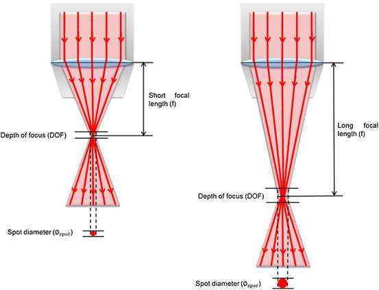
Image from Wood Science and Technology
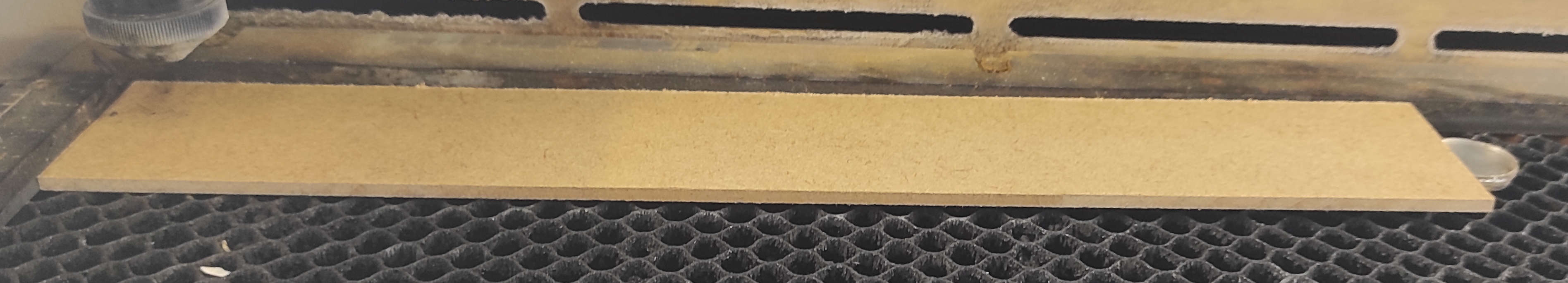
The first part of our group assignment was to get the Focus right. In our case, we used the epilog Fusion Edge a 30w CO2 Laser, which is equipped with an Autofocus(AF). The Material which we used for the test is 3mm HDF with a length of 300mm
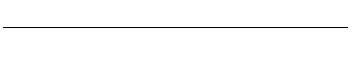
Image of our Testcut as file with a width of 290mm
To get a refference heights we first Autofocused the bed(focus 0,00mm) to check if the machine has the homepoint. After that, the 3mm testpiece is inserted and the focus was measured by the autofocus with an output of 2.67mm, which we took now as our refference. From there we start the First Test. For that the table was lowered by 5mm, the 3mm piece inserted and a piece of rectangle 10mmx10mm steelbar was placed under the rigth side of the testpiece.
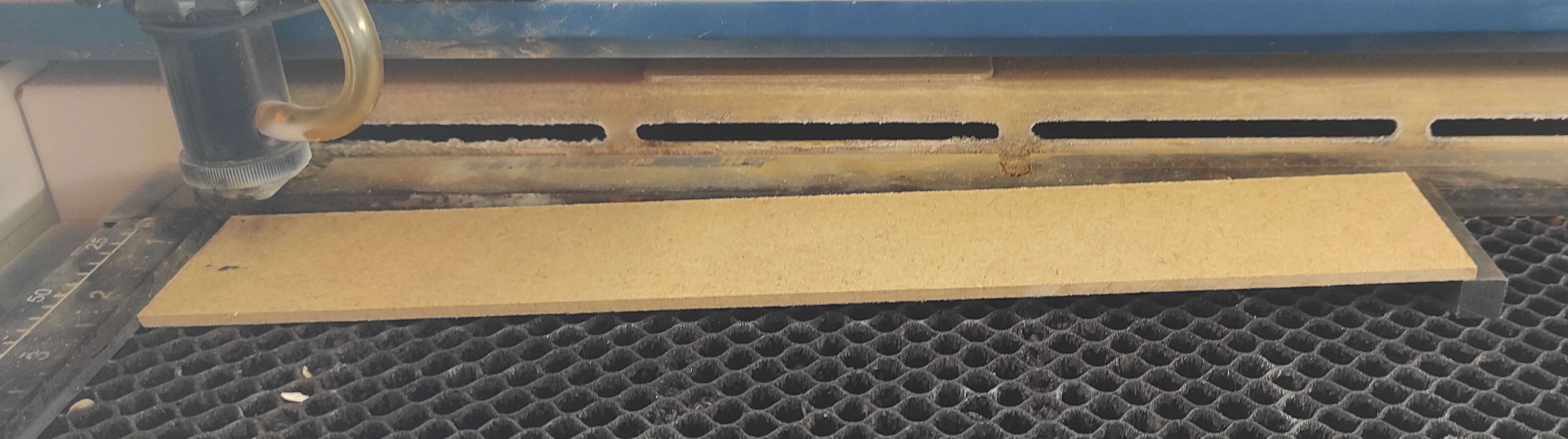
Now the Testcut
You can see, that the Best Area is in the middle. If you look more to the edges, you see, that the cut gets broader, because the the focal point shifts to over or in/under the material. This lead to a bigger area where the beam hits the material.
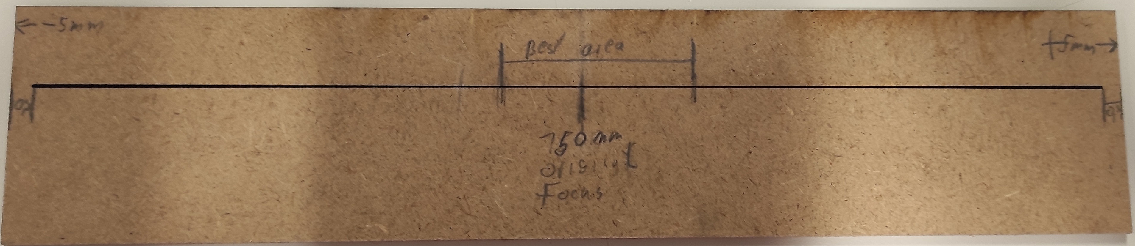
So at the next Testcut we went with a difference of +-2mm, which was archieved by setting the Table 2mm under the throug the AF determend bedheight. So now we have -2 for the +2 part i added 2x2mm pieces of Acrylic. so in total we have |-2mm|AFRef|+2mm|
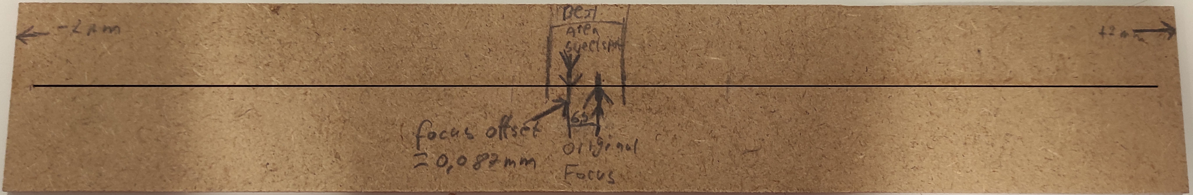
now comes the "tricky" part. The diviation needed to be calculated with the Pythagorean theorem. The First number we needed were a1=2mm and b1=150mm. We looked where the best cut spot or thinnes area on the cutting line was was and we measured from there to the center point. In our case it was b2=6,5mm.
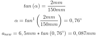
image made with Equation Editor for online mathematics
So our conclusion is, that the Autofocus of our machine was off by 0,087mm
Kerf
Kerf refers to the width of the material that is removed during a cutting process. This can be observed when using tools like a table saw, where the blade cuts through the material, or with laser cutting, where the beam of the laser has a specific width. Just like the width of the table saw blade that cuts through a board, the width of the laser's beam is known as the kerf. The kerf can be calculated by making consistent cuts over a specific distance.
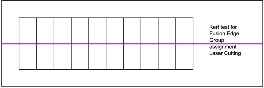
The first material we tested, was 3mm HDF Here we made 11 cut and over a distance of 100mm. Once we had our cuts we measured the regtangles we had a distance from 99.02mm. Than we get our total kerf (100-99.02)mm=0.97mm. Next we needed to find the total kerf per cut. Which is out Total kerf divid by the number of cuts. In our case we have a kerf of 0.97/11= 0.088. Now we want to divid the kerf by 2 and we end up with a Kerf of 0.044mm.

With this method, we obtained the kerf to be the following:
| Material | Kerf [mm] |
|---|---|
| Plywood 3 mm | 0.044 |
| Acrylic 3 mm | 0.08 |
| HDF 3 mm | 0.044 |
Materials
To determine the optimal laser cutting parameters for various materials, we employed a sample testing approach using an Inkscape files. The first featured a matrix design of rectangles using different colors to make the rectangles distinguishable for the epilog software and manually assign different power and speed settings while maintaining a constant frequency. The second file was used after determining the parameters, to determine the kerf for every material.
Overview of the Optimal Settings
The following table concludes the optimal settings for the materials with respect to speed, power and frequency of the laser.
| Material | Speed [%] | Power [%] | Frequency [%] |
|---|---|---|---|
| Plywood 4 mm | |||
| Acrylic 3 mm | |||
| HDF 3 mm |
Plywood 4mm
Acrylic 3mm
HDF 3mm
Joint clearance: Chamfer and Flexure Joint
Determining the appropriate tolerances is essential to achieving the best
fittings for flexure and chamfer joints. Therefore, parametric combs were used. A parametric comb has
slots with different widths depending on the laser cutter's kerf and the material's thickness. To test
this, we selected Plywood that was 4.00 mm thick (for chamfer joint) and 3.00 mm thick (for flexure
joint) for the task. The Kerf was already determined to be 0.04 mm.
- Enter the Fusion 360 parameters.
- Choose "Save as DXF" from the menu when you right-click on the sketch.
- Launch Rhino 7 open the DXF file, and arrange different elements using color coding (red for
engraving, blue for cutting).
- Remove projection lines
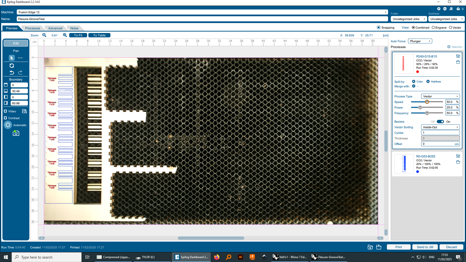
- Forward the file to the Epilogdashboard laser cutter software.
There set the optimal settings:
For the engraving:
- 50%speed
- 25%power
- 50%frequency
For the cutting:
- 20% speed
- 100% power
- 100% frequency
Press Fit With Chamfer Joint
Chamfer was chosen because it is a simple type of joint that helps guide the piece to slide smoothing into its slot. For this test we used two parametric combs made out of plywood. The first one had a range of “Thickness of material – 0.30 to Thickness of material + 0.30” for the slots’ width (in steps of 0.05). The second comb had a range of from “Thickness – 1.50 * Kerf to Thickness + 1.50 * Kerf (in steps of 0.25).
.jpg) with kerf
with kerf
.jpg) without kerf
without kerf
After passing the gravity test, we determined that Thickness – 1.50 was the best fit. The Kerf was very marginal that it did not really change the fit of the joint.
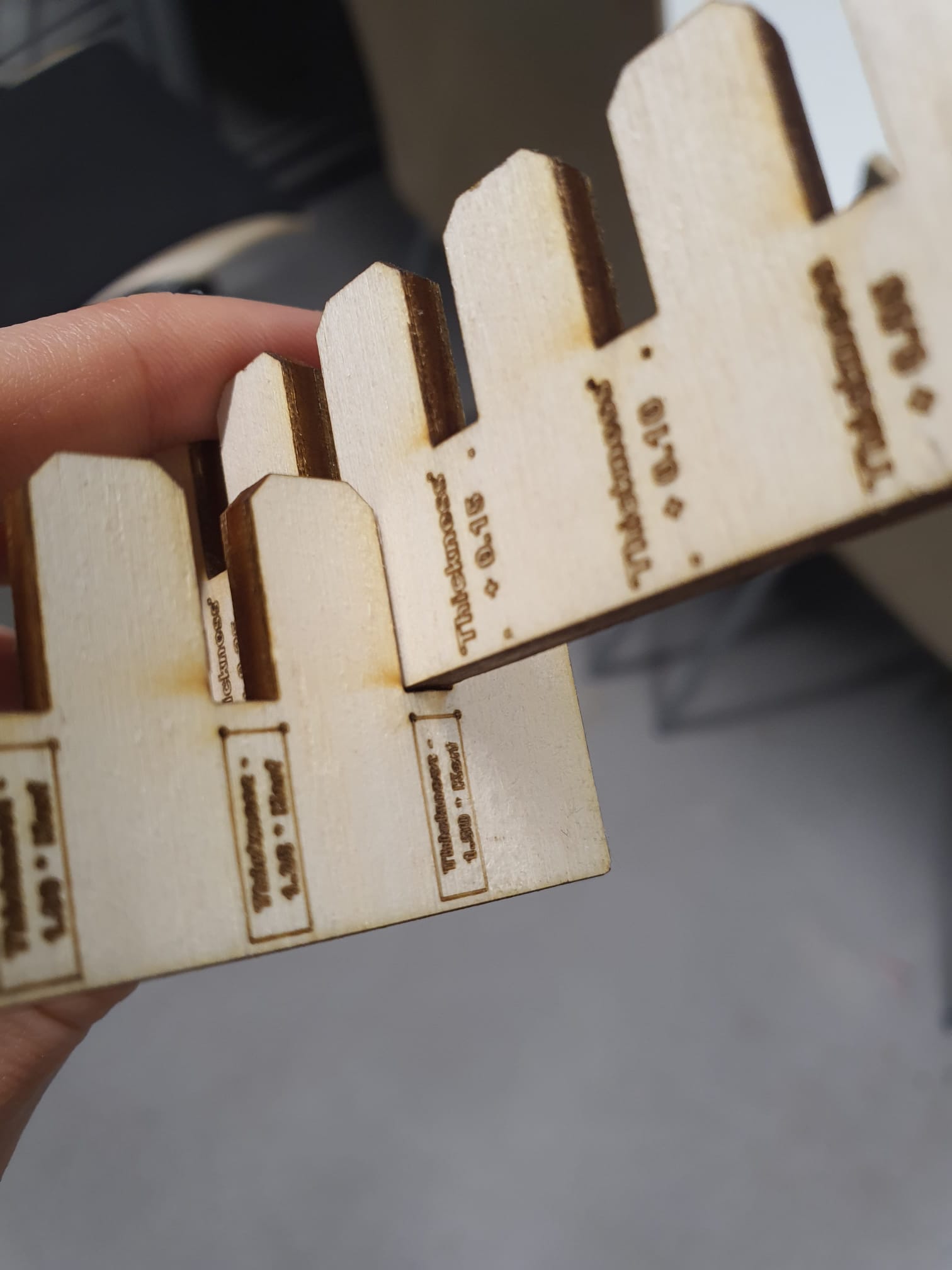
Flexure Joint
Flexure joint was selected because it secures the pieces, with two pin-like structures that can flex, and wider tip on each of them. The optimal thickness for these flexures is the one that is flexible and strong enough so it does not break off from long-term usage. For the best thickness of those For this test we used one parametric comb made out of plywood and a groove comb to test the flexures with. The thickness of the flexures ranged from “Thickness of material * to Thickness of material *0.80” (in steps of 0.05). The gap between the two flexure was constant = 0.39 mm, so it fits the grooves in the test comb.
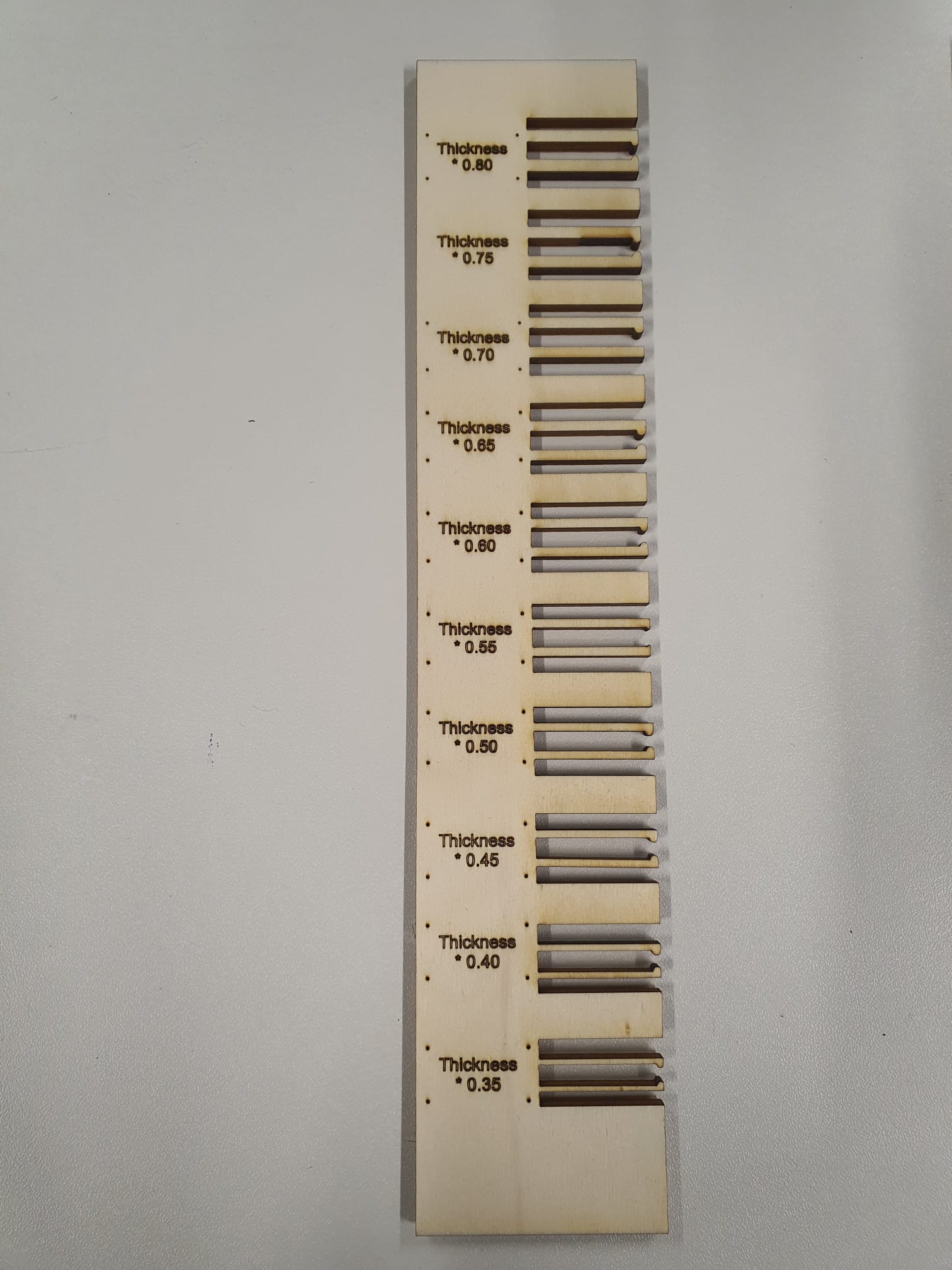
We figured that the best groove-flexure fit to be between Thickness of material * 0.40 and Thickness of material * 0.50. This depends on your preference on how tight you want the pieces to fit together
.jpg) thickness*0,4
thickness*0,4
.jpg) thickness*0,45
thickness*0,45
.jpg) thickness*0,5
thickness*0,5