10. Make my device talk, move, etc
Note: This week’s documentation is still work in progress
This week was about learning how to deploy different output devices, such as motors, LED, sound, etc, to enable my device to convey information to a human user.
An output device is any piece of computer hardware that converts data or information from a computer into a form that a human can perceive, such as visual (text, images, videos), audio, or tactile output. - Wikipedia
This week was one of the most unfruitful and disappointing week of FabAcademy (still, arguably not as unfruitful as the upcoming Wildcard Week!).
I had many big hopes for this week, but was met with many failures due to a combination of inadequate understanding, lack of time, and unrealistic goal-setting.
In the end, I didn’t manage to get a working system within the week; as the board I made was barely functional, and my motors didn’t move properly. The biggest takeaway from this week was to not be over-ambitious with making progress on the final project, but break goals down into realistic learning objectives, that can be achieved in the limited time I have.
So a lot of the work for this week was completed in the following weeks, and I have documented them under “Take 2”.
This week’s assignments (Mar 25 - Mar 31):
Group assignment:
- Measure the power consumption of output device(s).
Individual assignment:
- Add an output device to a microcontroller board I’ve designed and program it to do something.
Groupwork: Measure power consumption of output devices
In this week’s assignment, we learnt about the concept of power management, i.e., being aware of the working voltage and curent requirements of different devices. Understanding this enables us to prepare the right power that supplies the required current/voltage for our devices to function properly.

We also received a very helpful lecture on Basics of Electricity from the FabLab Kamakura guru, Yamamoto-san, and we gained a more thorough understanding of some basic concepts such as Ohm’s Law.
- I was finally able understand the relationship between current and voltage;
That current occurs when there is voltage across 2 points, and the bigger the voltage, the bigger the current, unless there is resistance, which acts inversely proportional to the current.
- When there is a voltage divider, the voltage is halved, and but the current nearly doubles as a result of having 2 channels.
- I also learned a very important safety precaution when handling motors; since they involve high current, it's important to ensure that the Ground and Power wires don't touch while connected (to avoid short circuit), by using masking tapes, for example.
- What's an H Bridge??
Add output devices to my board (Take 1)
My hope for this week was to experiment with different motor options in order to narrow down on the device that can signal the location of different spices in an effective and power-efficient way.
Unfortunately this week ended with a dysfunctional board because of several different reasons; a combination of inadequate understanding about actuating motors, and too little time (only the weekend).
1. Planning

2. Understanding the Output device
I started by doing some reading up on different types of Motors and how to select the right one.
Based on some research, I found out that selecting motors involves 4 important parameters, namely;
- How heavy the motor needs to lift
- How fast you want the motor to move
- How quietly you want it to move
- How heavy you want it to be
Stepper Motors:(https://fabacademy.org/2020/labs/kamplintfort/students/kais-alila/assignments/week12/)
A stepper motor it’s a specific kind of electrical motor which is able to turn its shaft within precise angles. It requires a dedicated driver which takes as input a simple digital on/off signal. Stepper motor are the most widely used motor in digitally controlled machines, especially the one found in a Fab Lab.
< Motors
xx
Because there were no vibration motors in FabLab Kamakura’s inventory, I decided to make my debut to Tokyo’s electric town, Akihabara.

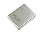
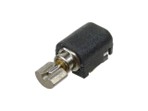
I bought 4 vibration motors to compare, and connected them to the Regulated power supply to test that they work, and to figure out the power requirements (working voltage and current).
Always connect Ground first,
Tape the chords down to prevent them accidentally touching
Motors typically require more current, and it’s important to understand the specific power requirements of each devices first, and design a circuit that supplies the right amount of current.

These were the readings I got:
| Motor | 円盤形 ブラシレス振動モーター (Disk-shaped brushless vibration motor) | リニア振動アクチュエーター (Linear Oscillatory Actuator) | 円筒形 振動モーター (Cylindrical vibration motor) | Mini vibration motor 2.0mm (Seeed) |
|---|---|---|---|---|
| Image | 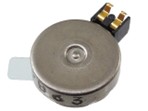 |
 |
 |
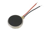 |
| Price | 50 JPY | 80 JPY | 60 JPY | 180 JPY |
| Site | Link | Link | Link | Link |
| Working Voltage | 2V (1.8-4.5V) | 3~6V | 2V | 3V (2.5-3.5V) |
| Working Current | 50mA | 70mA | 80mA |
3. Testing the circuit
The other approach I wanted to explore was sending electricity through copper wire coils to create an electromagnetic field around it. I thought that this would potentially be a very cost-effective way of achieving my goals.
First, Nagano-san showed me how to make a simple circuit for an air core coil (electromagnetic copper wires simply wrapped around hollow core).

Then by referring to Nagano san’s Fabricademy Documentation, I breadboarded a circuit for the same simple coil electromagnet, using MOS-FET and battery power source.

It worked at the 9V that Nagano san tried. I also measured the resistance, which was xx , in order to figure out the current, which was xx. In hindsight, I should have tested the coil at a lot wider range to identify the specific voltage at which the coil functions.
I didn’t really understand why we needed a MOS-FET, but I learnt later that it is because of the very high current that the coil produces (It requires very high voltage, but its resistance is very small). The circuit needs to endure current rise of 10 to 20 times.
Yamamoto san also showed me a little flag contraption that I would love to try implement.

According to him, in order to produce a larger inductance, we often wrap the wire around magnetic rods such as iron or steel. (Because magnetic energy attempts to take a specific path, flowing from the center of a coil, out one end, down the sides and then reversing that path. If a iron or steel core, called a solenoid, is shaped to fit this path, it will then direct the flow of magnetism through it.)
4. Designing and fabricating my board
I decided to make a board to compare my vibration motors, and also to deploy my electromagnetic coil.
The idea was to make a board on which I can prototype and compare different motors with different power. But I made a critical mistake of not thoroughly considering and testing the circuit before moving onto board fabrication, that I ended up with a non-functioning board.
Unfortunately, I had made quite a few mistakes with my board, that it was not really functional.
I had such a limited time that I became too focused on finishing the board, and
Mistake #1: Using voltage divider to supply the required voltage
As some of my motors required 2V, which is lower than the 3V supplied by my Xiao.
My instructor told me I could either use a voltage divider or voltage regulator to achieve this. However, the Voltage Divider was not ideal as the large current draw of motors could cause the voltage to fluctuate.
Mistake #2: Placing both diode and condensor for the motor, rather than just either
Sometimes voltage moves to the other direction when motor switches on/off, sending large current back to the Micro-controller, which we want to avoid. This is why a Diode or condenser is sometimes recommended.
Some of my motors have set current direction. This could have been prevented if I had tested the circuit, but due to the lack of
Mistake #3: Not understanding the power requirements of the coil beforehand
5. Testing the board
Before designing my custom PCB board, I should have tested the circuit with capacitor/diode and motor, and I should have tested the copper wire electromagnet first and figure out the optimum voltage and coil first.
Add output device to my board (Take 2)
I found the vibration of motors too weak
Considering the large number of motions I will have to make, 80 JPY per device feels a little too expensive for the little benefit they bring.
Based on this learning, I decided that I should prioritize Price and Long-life as my priority for choosing the output device.
1. Testing vibration motors
There are severals ways to supply the required voltage, and when we are supplying to Motors, Regulators or MOS-FETS are typically recommended.
3-terminal voltage regulators and MOSFETs, serve distinct functions: regulators stabilize voltage, while MOSFETs act as switches or amplifiers, with the former using the latter as a key component in some designs.
3-Terminal Regulators
is a component that outputs a constant voltage.
It constantly checks whether the voltage it supplies deviates from the target voltage, and if it does, adjusts it so that the voltage reaches the target value. Any excess voltage greater than the target voltage is released as heat.
Switching Regulators
While 3-Terminal Regulators only supply voltage that’s lower than input Voltage, A switching regulator can amplify the voltage.
MOS-FET
- 電子工作の素、549.0 5123 p79,
試作したいデザインを幾つか検討して絞り込む いつまでに何個試す??
理事会の日は6月何日? それまでに、能登の計画、誰にインタビュー必要か、 Final Project何処まで終わらせるか
くれぐれも直接電池に繋げないこと 0.2 で買った 細い方が抵抗が大きい 試作してみて計算する 100Ω 電流の量を流れないように付けている 測った方が良い 重さによる 今のは10-20mアンプで十分 方向はFETかドライバーで変えられる
モータードライバーのICが必要になる 20本の信号線が必要
Using PWM - 電子工作パーフェクトガイド Page 148
2. Connecting Neo-pixels
3. Understanding Electromagnetic coils
Useful links:
Files:
Reflections:
This week I learnt to…
- Demonstrate workflows used in controlling an output device(s) with MCU board I have designed.
Looking back, I was over-ambitious at the planning stage, and I tried to cram too many things which led to me skipping some critical steps to finish in time.
Sometimes we can’t deploy all our ideas for the final project in one week, so we need to start with scoping out realistic learning objectives for the week
I would like to learn about implementing PWM
Assignment Checklist:
- [ ] Linked to the group assignment page
- [ ] Documented how I determined power consumption of an output device with my group
- [ ] Documented what I learned from interfacing output device(s) to microcontroller and controlling the device(s)
- [ ] Linked to the board I made in a previous assignment, or documented my design and fabrication process if I made a new board
- [ ] Explained the programming process/es I used
- [ ] Explained any problems I encountered and how I fixed them
- [ ] Included original source code and any new design files
- [ ] Included a ‘hero shot’ of my board
Flip-disc display elements (close up). The disc rotates on the shaft that is carried in the two triangular posts. The magnet that powers the rotation can be seen embedded in the disc. Under the disc is the driving solenoid; when powered, a field is induced into the two posts, flipping the discs. Rotation stops when the disc hits the post. https://en.wikipedia.org/wiki/Flip-disc_display
https://hackaday.com/2023/03/03/a-close-look-at-how-flip-dot-displays-really-work/
Solenoids are a specially engineered electromagnet in which a coil of wire is wrapped around a specially shaped core made of steel or iron, it is an integral component in all sizes of motors.
Solenoids work like this: when electrical current goes through the loop of wire, a magnetic field accumulates around it. A iron or steel path for this force to flow into significantly increases the strength of the magnetic field. Because magnetic energy attempts to take a specific path, flowing from the center of a coil, out one end, down the sides and then reversing that path. If a iron or steel core, called a solenoid, is shaped to fit this path, it will then direct the flow of magnetism through it.
https://gigazine.net/news/20240627-flipdisk-display/ https://flipdisc.io/
https://fab.cba.mit.edu/classes/863.23/Harvard/people/Dunya/final_project/idea1/
https://www.youtube.com/watch?v=oryYiSg3wlI