10. Make my device talk, move, etc
Our goal for this week was to demonstrate workflows for controlling different output devices, such as motors, LED, sound, displays.
👉An output device is any piece of hardware that converts data or information from a system into a output form that a human can perceive, such as visual (text, images, videos), audio, or tactile. - Wikipedia
This week was one of the most unfruitful and disappointing week of FabAcademy (though arguably not as unfruitful as the upcoming Wildcard Week)😫. I had many big hopes for this week, but was met with many failures due to a combination of inadequate understanding and planning, and lack of time (I only had 2 days this week due to a business trip).
In the end, I didn’t manage to get a working system within the week; the board I made was barely functional, and none of my motors moved properly. My takeaway from this week was to not be too ambitious with making progress on the final project, but break goals down into realistic learning objectives, so that they can be achieved during the week.
A lot of the assignment criteria for this week was completed in the following weeks, which are documented under “Take 2”.
Group assignment:
- Measure the power consumption of output device(s).
Individual assignment:
- Add an output device to a microcontroller board I've designed and program it to do something.
Groupwork: Measure power consumption of output devices
For this week’s Group assignment, we learnt about the first step of designing power supply, which is about being aware of the working voltage and curent requirements of our devices. All output devices have specific power requirements, so we always need to start by understanding those requirements in order to prepare the right power source that can supply the required current/voltage for our devices to function as intended.

We also received a very helpful lecture on Basics of Electricity from the FabLab Kamakura guru, Yamamoto-san, and we gained a much more thorough understanding of basic Electrical concepts such as Ohm’s Law.
📝My learnings:
- I was finally able get my head around the relationship between current and voltage;
Current occurs when there is Voltage across 2 points, and the bigger the voltage, the bigger the current, unless there is Resistance, which acts inversely proportional to the current. - I was also surprised to learn that when there is a voltage divider, the voltage is halved, but the current nearly doubles as a result of having 2 channels - making the power double! (This is also in line with the 2nd Ohm’s Law which stipulates that Resistance is inversely proportional to the thickness of the wire)
- I also learnt about some important Safety Considerations when handling output devices; since they often require large amount of current, it’s very important to understand the precautions before handling them (read below).
Power electronic devices like motors require very high current, so remember;
Grounding: Always connect Ground first, to de-energise.
Avoid short circuits: Tape the chords down to prevent them from accidentally touching. Keep the space clutter-free.
Avoid jewellery and wear insulated shoes: Keep your body away from grounded surfaces like metal tables or pipes, and use insulated mats if necessary.
Effects of Current on the body:
This is dependent on multiple factors such as AC/DC, duration, path through the body, and the resistance of our body, but in general, keep these values in mind;
1mA: You can feel a tingle, but it's fairly harmless.
5mA: Slight shock is felt.
6-25 mA: Painful shocks. Loss of muscle control. Especially for women.
9-30 mA: The freezing current or “let go” range. If extensor muscles are excited by shock, the person may be thrown away from the power source. Individuals cannot let go.
50 to 150 mA: Extreme pain, respiratory arrest, severe muscle reactions. Death is possible😵
Over 1 Amp: Highly lethal💀
Our body's electrical resistance vary significantly, ranging from 300Ω (internal tissues) to 100kΩ (highly dry skin). It is especially low around the internal issues such as bruises due to its high moisture and presence of salty conductive fluids.
Add output devices to my board (Take 1)
My hope for this week was to experiment with different motor options in order to narrow down on a device that can signal the location of different spices in an effective (as well as cost and power-efficient) way.
1. Planning
For my spice rack, I wanted to play with the idea of spices making animated motions to signal the location.

Because I would be deploying a large number of devices, I needed to find an effective means of output that is low power and low cost, small and light-weight. I also wanted it to be long-lasting, as needing to replace parts frequently would create a lot of burden for the user. Due to these reasons, I initially scoped out LEDs, not realising that Motors would be even more challenging!
2. Understanding Motors
2.1 Basics of Motors
I started by doing some research on different types of Motors to select the appropriate one.
👉The basic principle of motors is the electromagnetic force that’s generated when current flows through coil of wire. The strength of the rotating force depends on either 1. the amount of current, or 2. strength of magnetic field, which is the number of turns of coil. This is why stronger motors tend to be heavier and larger in size.
The different types of motors below differ in terms of their Power Source (AC or DC), and their control mechanisms;
👉What are the main types of Motors?

* As name suggests, uses Alternating Currents to create the rotating mechanism.
* Used often in industrial applications, due to its high-power, robustness and lower maintenance.

* Uses direct current and a mechanism that consists of spinning coil and stationary magnets around the coil.
* Often used in smaller electronics and vehicles, especially when there’s need for precise speed control.
* Most common types are Brushed typess and Brushless types.


* Usually operates with DC power.
* It has the ability to turn its shaft at precise angles (steps), due to its dedicated driver which can read digital on/off signals.
* 1 “step” is approximately 1.8°.
* Has high torque at lower speeds, but generally not very good at high speeds.
* Often used in digitally controlled machines such as printers, CNC machines, security cameras, etc.

* Can be AC or DC.
* Utilizes a feedback system (like an encoder) in a closed-loop control loop to ensure they reach and maintain a commanded position.
* It offers excellent speed and precise control over a wide range of speeds.
* Used in areas where exact movements are crucial, such as arm control in robotics, CNC machining, automated manufacturing,medical imaging, consumer electronics, etc.
👉 It’s also useful to consider these 4 Important factors when selecting motors;
- How heavy the motor needs to lift
- How fast you want the motor to move
- How quietly you want it to move
- How light you want the motor to be
Eventually, I decided to try 2 low-cost approaches suggested by my instructors; the vibration motor and electromagnetic coils.
Because there were no vibration motors in FabLab Kamakura’s inventory, I decided to make my debut in Tokyo’s electric town, Akihabara, and got 4 different vibration motors to compare.

2.2 Measuring Power Requirements
I started by connecting the motors to the Regulated power supply to test that they work, and to figure out the power requirements (i.e., the working voltage and current).

These were the readings:
| Motor | 円盤形 ブラシレス振動モーター (Disk-shaped brushless vibration motor) | リニア振動アクチュエーター (Linear Oscillatory Actuator) | 円筒形 振動モーター (Cylindrical vibration motor) | Mini vibration motor 2.0mm (Seeed) |
|---|---|---|---|---|
| Image | 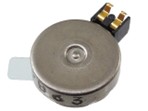 |
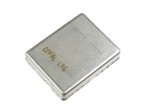 |
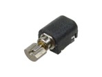 |
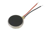 |
| Price | 50 JPY | 80 JPY | 60 JPY | 180 JPY |
| Site | Link | Link | Link | Link |
| Working Voltage | 2V (1.8-4.5V) | 3~6V | 2V | 3V (2.5-3.5V) |
| Working Current | 50mA | 70mA | 80mA |
3. Designing and fabricating my board
This week I hoped to make a board for comparing different output devices such as vibration motors and electromagnetic coils. The idea was to make a board on which I can test and compare different motors with different power.
However, in rushing to complete the board in 2 days, I missed few critical steps and components. To start with, the datasheet provided for some of the motors were limited, with only one of the motor recommending Zener Diode or capacitor for Power regulation. So I made a mistake of assuming that it would be as simple as connecting them up to 3V and Ground pins🤦🏻♀️
Also, I should have designed in appropriate Voltage supply. My instructor told me I could either use a voltage divider or regulator to reduce my supply voltage from 3V to 2V, so I decided to go with the familiar Voltage Divider. However, this was later cautioned against by Yamamoto-san as dangerous, as the high load of the motor causes the voltage to widely fluctuate.
If I had taken the time to test the circuits with breadboard first, I would have noticed all the shortcomings, but in the rush of trying to fabricate it all before my business trip, I just ended up producing a mostly non-functional board.

I also rushed my soldering, the result looks embarassingly messy…🙈
Later, I learnt that there are a number of critical components that should be considered when implementing Motors:
- MOSFET: Enables us to manage the high current and voltages required for motors, using low-power control signal. There are 2 types, depending on the amount of supply voltages. With motors, they typically work on more than 2V, so we tend to use N-MOSFETS.
- 3-Terminal Regulators: A component that outputs a constant voltage, and can be used as an alternative to MOSFETS. It constantly checks whether the voltage it supplies deviates from the target voltage, and if it does, adjusts it so that the voltage does not exceed the target value. Any excess voltage greater than the target voltage is released as heat. (Due to this, it usually requires addition of heat-sinks.)
- Pull-up/Pull-down resistor (1k/10kΩ): To make sure the MOSFET is fully off when there is no signal.
- Transistor: Recommended to filter out noises. Usually around 10 to 100pF.
- Diode: To protect against reverse current flow.
4. Electromagnetic coil contraption
Anther approach I tried to explore (which also didn’t make it through) was sending electricity through copper wire coils to create an electromagnetic field. I thought that if I could generate enough torque to lift a bottle, it would be fun seeing the spice bottles bob up and down.
Nagano-san showed me how to make a simple circuit for an air core coil (electromagnetic copper wires simply wrapped around hollow core).

Referring to Nagano san’s Fabricademy Documentation, I breadboarded a circuit for the same simple coil electromagnet, using MOS-FET and battery power source. A 9V battery worked well, but in hindsight, I should have tested the coil at a lot wider range to understand the torque versus voltage level. I should have also measured the resistance, which should be very small, in order to also figure out the working current.
Either way, I realised that achieving enough tourque would be quite a challenge, especially with such small budget and shelf space, so gave up on this approach.
Take 2 - Charlieplexing with LEDs
After my failed attempts, I concluded that, given the difficulty of actuating motors, trying to actuate so many at a time was too big a challenge to attempt in 1 week of FabAcademy. Moreover, considering the large number of motions I would need to make, the cost and power requirements felt too high for the little benefit they bring.
Based on this conclusion, I decided to continue to prioritising price and long-life, and settled on good-old LEDs for now. For this week’s assignment, I decided to try understand Charlieplexing; a technique for controlling a large number of LEDs using minimum number of pins, by leveraging the three-state logic of pins and the one-way nature of diodes.
After reading about its mechanism, I drew a circuit for controlling 6 LEDs with 3 lines;

And I made a logic table.
| LED: | 1 | 2 | 3 | 4 | 5 | 6 |
|---|---|---|---|---|---|---|
| 1 | Low | High | - | - | Low | High |
| 2 | High | Low | Low | High | - | - |
| 3 | - | - | High | Low | Low | High |
And I wrote this simple code;
// Xiao ESP32C3 Program for CharliPlexing with 3 lines & 6 LED's

#define led_pin1 D8
#define led_pin2 D9
#define led_pin3 D10

  void setup() {
    Serial.begin(115200);// initialize serial communication at 115200 bits per second
    pinMode(led_pin1,OUTPUT);
    pinMode(led_pin2,OUTPUT);
    pinMode(led_pin3,OUTPUT);
  }

  void loop() {
    Serial.println("Lighting up");
    digitalWrite(led_pin1, LOW);
    digitalWrite(led_pin2, HIGH);
    delay(100);
    digitalWrite(led_pin1, HIGH);
    digitalWrite(led_pin2, LOW);
    delay(100);
    digitalWrite(led_pin2, LOW);
    digitalWrite(led_pin3, HIGH);
    delay(100);
    digitalWrite(led_pin2, HIGH);
    digitalWrite(led_pin3, LOW);
    delay(100);
    digitalWrite(led_pin1, LOW);
    digitalWrite(led_pin3, HIGH);
    delay(100);
    digitalWrite(led_pin1, HIGH);
    digitalWrite(led_pin3, LOW);
    delay(500);
  }
I then wired up the circuit using the board I made last week, deployed the code using Arduino IDE, and all 6 LEDs managed to light up🙌🏻
(Please excuse the scrappy setup as at this time I had no access to the lab or instructors.)

Useful links:
Files:
Reflections:
This week I learnt the importance of always starting with scoping out realistic and specific learning objectives for the week. In hindsight, I was over-ambitious given the short amount of time available and all the considerations that come with actuating Output devices. I also learnt the importance of testing the circuit throughly before moving onto Board fabrication.
In terms of actuating Output Devices, I learnt 2 key concepts in Output device actuation; Electrical safety and Power supply design. Specifically I learnt that voltage dividers are not a smart way to control voltage, and started to understand about 2 important components: MOSFETS and 3-Terminal Regulators.
❓Further Questions:
- I’d like to understand the mechanisms of MOSFETS (and Transistors in general), and 3-Terminal Regulators, and how to choose the appropriate one
- What’s an H Bridge??
- I’d really like to understand better the numerical relationship between Resistance (Ohms), Current (Amps), Voltage (Volts) and Power (Watts).
💡Ideas for the future:
For my final project, perhaps I could compromise by making little flag contraptions like this one that Yamamoto san made.

Or I could take inspiration from flip disc displays. But all in good time!
Assignment Checklist:
- Linked to the group assignment page
- Documented how I determined power consumption of an output device with my group
- Documented what I learned from interfacing output device(s) to microcontroller and controlling the device(s)
- Linked to the board I made in a previous assignment, or documented my design and fabrication process if I made a new board
- Explained the programming process/es I used
- Explained any problems I encountered and how I fixed them
- Included original source code and any new design files
- Included a ‘hero shot’ of my board
-
Reference for Motors: Seeed, Documentation, HVH, Engineers Guidebook ↩