FreeCAD
Dimensions and constraints
Here are one minute clips (in Neil's style) that demonstrate the heart of CAD.
Dimensions and constraints in 2D sketches are how you make exact geometry for fabrication. To follow along, create a new file in FreeCAD, select the Sketcher workbench and create a new sketch:


To exit a command, right click anywhere in the model viewport.
A simple exercise
Model a stamp handle to get a feel for dimensions and constraints.
Create a new FreeCAD file, select the Sketcher workbench and model half of a stamp handle. Good CAD practice is to fully constrain all the geometry in each sketch, then the lines turn green. Fully constrained means that you can't drag geometry with the mouse. To modify it, you double click the dimensions and change them. This makes for a robust and predictable CAD model that you won't modify by accident.
When the sketch is finished, press the Close button in the Tasks pane on the left of the screen to close the sketch.
Then select the Part workbench and use the Rotate command to turn the sketch into a 3D object.
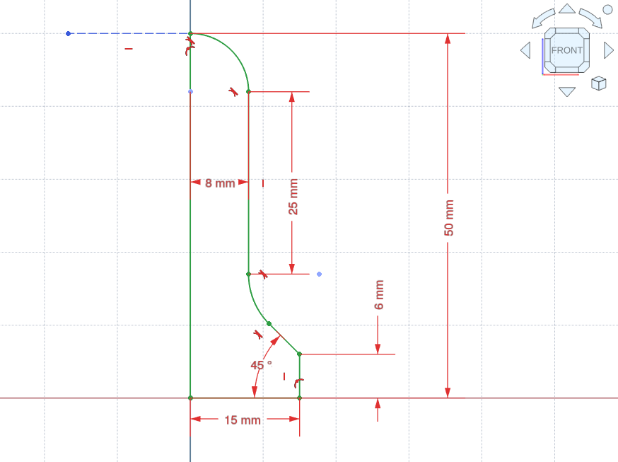 I recommend putting the sketch on the front plane (the XZ plane). To make a smooth sphere on top of the handle, you can do a little trick. Draw a horizontally constrained line connected to the top of the arc. Then you make the arc tangent to that line. To make sure that this extra line isn't included in the Revolve command (which throws an error), make the extra line a construction line..
Tip
When you input a number into a field in FreeCAD, you can click the number and scroll up and down to increase and decrease. You can also input calculations and FreeCAD does them for you.
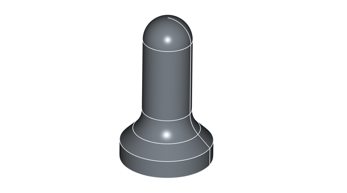
Use the Revolve command in the Part workbench to turn the 2D sketch into a 3D object.
If you want to 3D print the stamp handle::
- Select the model and go into File -> Export.
- Under Files of Type, select the 3D Manufacturing Format (*.3mf), which is at the top of the list.
If you want to be able to view the model from all angles on a website:
- Select the model and go into File -> Export.
- Under Files of Type, select WebGL file (*.html).
If you want to complete the stamp; either emboss a design directly on the bottom of the stamp handle in the 3D model, or make a 2D design and order some laser rubber:

A nicer interface
FreeCAD looks like this:

At Fab Lab Ísafjörður we've found that students never remember where the CAD commands are (in the toolbar at the top of the window), because all you have is small unlabeled icons. You can hover over the icons and get the names of the commands, but this could be better.
We use an addon called FreeCAD Ribbon, which makes the program look like this:
 Much friendlier, right? More like the commercial CAD packages.
Note
There is a potential downside to using this addon: When you follow tutorials online, your FreeCAD looks different from their FreeCAD, which can be confusing. But you should be able to easily figure it out. The command names and icons haven't changed, just how they are arranged.
Setup
Warning
Since making these setup instructions, the FreeCAD Ribbon interface has evolved. We haven't updated the following instructions yet, so if you get stuck, contact @svavar in the Fab Academy Mattermost chat or send an email to svavar at fabisa dot is.
- Install FreeCAD on your operating system of choice.
- We recommend the Metric small parts and CNC unit system, because it plays nicely with the CAM workbench:
 We like the Blender navigation style; it's similar to SolidWorks and also makes it easy to switch between FreeCAD and Blender.
At our lab we don't use the Start page with Part Design as the default workbench, so we select this option:

Now, to set up the FreeCAD ribbon interface:
- Go into Tools -> Addon Manager
- Check both of these boxes:

- In the Addon Manager, install the LCInterlocking workbench.
- Close the Addon Manager and select Restart now
- Go into Tools -> Addon Manager and install FreeCAD Ribbon.
- Say yes to installing the dependencies:

- Close the Addon Manager and select Restart now
- If the BIM workbench starts bothering you, just close it
- Now you have big icons with no labels.
- Go into Menu -> Customize -> Ribbon preferences
- Check the following boxes:

- Close the Ribbon preferences and then select Restart now
- Now you have labels, but the button arrangement is a bit messy.
- Go into Menu -> Customize -> Ribbon layout
- The first time you open Ribbon design, it needs to generate a data file. Select Yes.

- The Ribbon design window should now open. If it doesn't respond, check if a BIM workbench welcome dialog has opened, and close it. Then the Ribbon design window should work. The BIM workbench welcome dialog may appear a few more times. Sigh and close it. If it still doesn't respond, restart FreeCAD and open the Ribbon design window again.
- Select Import layout

- Import the fabisa.json configuration file (you can keep that file anywhere you want, we put it in Documents/freecad-settings)
Grab our FreeCAD ribbon configuration file here:
fabisa.json (Right-click and select Save Link As)
- Ribbon design may ask you to select the configuration file again. You don't have to do it again, just close the file select dialog.
- Then the Update button at the bottom of the Ribbon Design window should become active. Click it. It should become inactive.
- Click Close.
- Select Restart now.
- If FreeCAD doesn't open automatically, just open it manually
- Now FreeCAD looks pretty!
You still have a little tweaking to do in the workbench preferences:
- Go into Menu -> Edit -> Preferences
- Select Workbenches
- Now drag and drop the workbenches in this order (or any order that makes sense to you):
 You can also select which workbench is active when you open FreeCAD. We like Part, but you can also stick with the default Part Design.
The workbenches below the highligted rectangle in the image above don't matter, because they aren't included in the Ribbon designer. When you use the Ribbon add-on, you can add or remove workbenches in Menu -> Customize -> Ribbon layout (in the Include workbenches tab). You could add the OpenSCAD workbench, for example.
- Restart FreeCAD
- Enjoy!
Note
We've removed the least-used tools from the ribbon interface, to make it less cluttered. If a tutorial calls for a command that isn't in the ribbon, you can always go into the top menu and find all the available commands there:

Part or Part Design?
There are two main modeling workbenches in FreeCAD, named Part and Part Design.
This confuses a lot of people.
Part is the original solid modeling workbench in FreeCAD. It's quite intuitive and powerful.
Part Design is a more recent attempt to create a "tree view" similar to commercial CAD packages:
 The 'tree' is the list of operations on the left, which shows the history of the model. You can edit the operations and rearrange them.
Part Design imposes a certain workflow that we don't like. We used the Part Design workbench in a Fab Lab class for one semester, but students had difficulties.
When you're working on a 2D sketch in one solid body in the Part Design workbench, you can't reference geometry in another solid body. To do that, you need to use a workaround called a Shape Binder, which isn't needed in any other CAD package. Referencing geometry to make sure that parts fit together is sort of the whole point of CAD, so we switched to the good old Part workbench last year, which we find both more intuitive, flexible and powerful.
You can use the Part workbench with other workbenches like Curves and Lattice2 to create advanced geometry:
The Part Design workbench doesn't play well with the other workbenches.
The Part workbench doesn't have array tools, but you can make rectangular and circular arrays of solid bodies in the Draft workbench. It's not ideal to have to switch workbenches for this, but we still like it more than using the Part Design workbench.
Note
Take our opinion with a grain of salt, because most tutorials online use the Part Design workbench. It is the default choice in FreeCAD. You're free to use Part Design if you like; many people do!
The Laser Cut Interlocking workbench
Our students design interlocking parts using the LCInterlocking workbench in FreeCAD.
Snap-fit furniture
The LCInterlocking workbench in FreeCAD is great for milling furniture that snaps together.
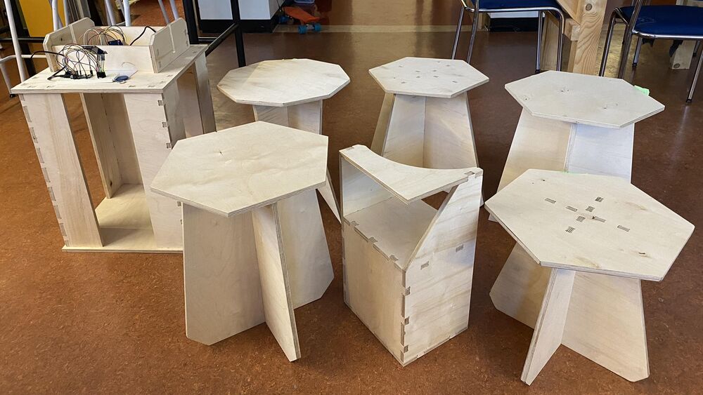 Part of the furniture that our secondary school students made in the fall of 2024.
We made a tutorial showing how to design this snap-fit stool using the LCInterlocking workbench in FreeCAD:
The second part is how to mill the stool in VCarve:
Unfortunately, these videsos are in Icelandic! We can quickly make English subtitles if anyone's interested; just send me a message on Mattermost (my username is @svavar).
Note
The main downside to the LCInterlocking workbench is that it doesn't allow parametric input when you're defining the joins. So when you measure the thickness of your actual material and modify the thickness defined in FreeCAD (ideally in a spreadsheet or VarSet), the parts that you modeled will update, but the joins won't. You then need to edit the joinery features in the tree and update the material thickness manually. Sometimes you need to delete the joins and make them again after editing the thickness. So we recommend measuring your actual piece of material down to the nearest 0.1 mm and putting that measurement into your CAD model in the Part workbench first, and then making the joins in the LCInterlocking workbench.
Should we fork the LCInterlocking workbench and add parametric input to it? We've figured out how to fork the workbench and we've started modifying it, but we haven't cracked how to add parametric input yet.
CAM workbench
FreeCAD is surprisingly powerful. You can mill things on a ShopBot and and other milling machines using the CAM workbench.
Brad Collette is the main maintainer of the CAM workbench. He's made good tutorial videos.
We followed the CAM walkthrough for the impatient and were able to do this:
Update: At the 2026 Fab Academy Instructor Bootcamp in MIT Fab Lab Lyngen, Norway, we convinced Jens Dyvik to have a workshop on milling metals using the CAM workbench in FreeCAD. He did very successful test cuts in aluminum and steel with a Lunyee desktop CNC: Desktop metal milling with FreeCAD
Note
In our experience, VCarve Pro / Vectric Aspire is the simplest and most convenient CAM program.
But the CAM workbench in FreeCAD (and also the CAM workbench in Fusion) can do all the same things and more. When you're ready to level up, try milling a simple part using the CAM workbench in FreeCAD.