Week 8 Electronics production
This page documents the group assignment for week 08 of Högni, Jóhannes and Ólöf.
Group assignment:
- Characterize the design rules for your in-house PCB production process: document feeds, speeds, plunge rate, depth of cut (traces and outline) and tooling.
- Document the workflow for sending a PCB to a boardhouse
- Document your work to the group work page and reflect on your individual page what you learned
Overview and approach
We did the group assignments in two different locations.
Ólöf worked with the MonoFab SRM-20 at Fab Lab Austurland and documented about it.
Högni and Jóhannes worked with the Roland milling machine at Fab Lab Ísafjörður and Högni documented about it.
We worked together online when placing an order at a PCB house and Jóhannes documented about that.
Characterizing our in-house PCB production
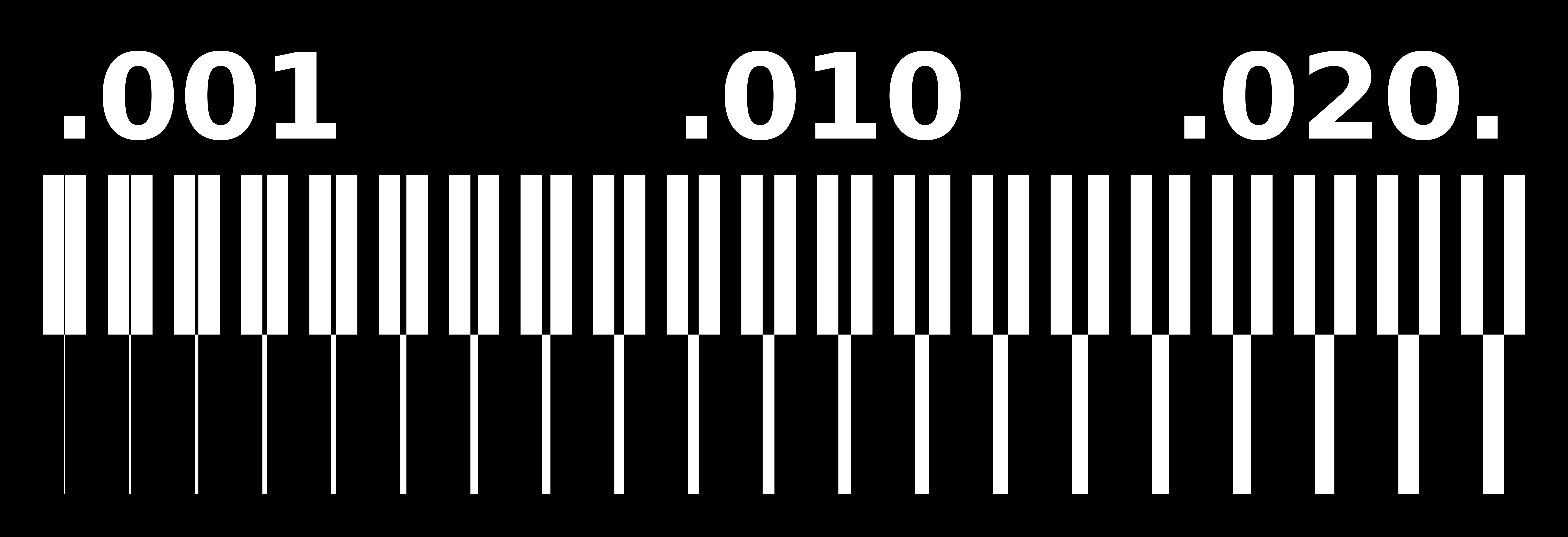
We used this milling test by Neil Gershenfeld to characterize our in-house PCB production. When performing this test we begin by doing the traces with a 1/64" endmill and we only remove the top layer of copper from the board. Then we do the interior with a 1/32" endmill and cut the outline. The cut goes all the way through, separating the PCB board from the plate.
Fab Lab Ísafjörður
The Roland MDX-20
In order to test the design rules of the machine we milled the same document twice with different milling bits (a thinner trace mill and v shaped cutter).

The results show how close you can lay the tracks together in a PCB design board and how narrow traces can be cut without delamination from the board. The left side of the picture is the result with a thinner 1/64 end mill and then the right is with a v-cut mill. The image quality that I got was not the best, but it looks like in the left image you could potentially go all the way down to 0.06 of an inch before you run into problems and on the right it is harder to see in this image, we may need to look the board again and update this page.
We used a piece of copper board that had previously been used and then we used following settings to place it in the correct position for milling.

However I made a mistake when attaching the mill and it was not tight enough and as a result it got loose and moved up, while cutting. This resulted in an incomplete cut.
 so we had to reattach the mill and run the exact same program again with better results.
To save time we decided to do both traces with the two different mills before cutting the outline and then do both outlines at the same time save one tool change.
For the second cutout we used the following settings, but a speed of 1mm/s.

Because it is hard to determine the exact cut width of the v-bit, we entered 0,1 mm which was less then the actual cutting width. Therefore the result isn't very expressive, but what can be seen from the board, is that the copper gets ripped of and it leaves a rough finish - nothing like the end-mill result.
We then needed to cut out the two outlines to get our final image. This turned out to be tricky because there was another cutout very close to the edge of our board. Also we ran into trouble, because the software didn't want to calculate a toolpath for the lower edge of the outline, even though we double-checked the width, resolution and tool diameter settings. Maybe this is a bug? The only solution we found was to reduce the tool diameter in the settings and "cheat" on the machine that way.

We used the 1/32 end mill and hence were able to cutout the board images that are at the top of this page.
Fab Lab Austurland
The MonoFab SRM-20
The MonoFab SRM-20
We have a MonoFab SRM-20 milling machine in our Fab Lab Austurland. It is usually used for milling PCB boards but according to this site it can mill all kinds of things.

Preparation for milling
In this video by Andri Sæmundsson it is shown how to mill the board by using Fab Modules here. Andri Sæmundsson was not using a MonoFab SRM-20 like I was, so I also watched this video by Fab Lab Barcelona here.
Andri Sæmundsson was using Fab Modules but we use Fab Mods, a newer edition, for setup before cutting and milling in the MonoFab SRM-20 machine. The Fab Mods website is used online. Here you can see an overview of Fab Mods. It looks very complicated but is very simple when you begin using it.

Choosing the right machine and what to create
I opened the website and right clicked on the screen for this window (upper left photo) to open up.
Then I chose Programs and clicked on Mill 2D PCB which was under SRM-20 mill (lower left photo).


Using .png image for the milling test
The first thing you do is look at the left on the screen and choose if you want to use .png or .svg and for this test we used the .png option. When you have chosen the .png image that you use for the milling test it appears in the window you can see on this image. The next step is to look at the settings in the window below (to be continued here below...).

Settings for the 1/64" endmill
You click on the size of the endmill you want to use. Here I clicked on the 1/64" traces when I milled the traces but when I cut the outline I clicked on the 1/32. As you can see in the photo on the left, the depth of the cut is only 0.004 inches and the speed is 4mm per second when cutting the traces.

Cut, plunge, jog, spindle speed...
As you can see in this image, the spindle speed was set to 1000 rpm, the plunge speed, jog speed and cutting speed was set to 4 mm per second. The jog height was set to 5 mm per second.

Offset
The offset was set to zero for fill. After adjusting all settings the Calculate button was clicked and the program showed a small preview of the traces. In the next tab on the browser an image of the traces appeared and you could see how the traces would be milled.

The Vpanel
You use the Vpanel to control the MonoFab SRM-20. You use the arrows to move the spindle around. You can control if you want to move it fast or if you want to move it in small steps by choosing between Continue, x100, x10 or x1. When you have put the endmill you want to use in the machine, you lower the endmill until it almost touches the plate. Then you loosen it and lower it carefully until it touches the plate. It is good to use one finger to press on the side of the endmill, so that it won't fall down. Then you click on the Z for setting the zero point for the Z-axis. Press the plate down while doing this.
The next step is to set the x- and y-axis. You move the endmill to the starting point and then click on the xy for setting the zero point.

Move a few millimeters up
Make sure to move the endmill a few millimeters up above the material before turning the spindle on, so that the endmill isn't touching the material when it starts spinning.
Adding a job
In the Vpanel you click on Cut. Then a window openes up. You begin by clicking on Delete all to remove former jobs and then you use Add to fetch the job you want to be done. You only do one job at a time. First I milled the traces, then I cut the outline.

Cutting in the air
I didn't notice that the origin settings were set to 10 on the x-, y- and z-axis. When the machine started to cut, it was only cutting the air. I had to go back to Fab Mods and change those settings. After that cutting the traces went well.


Loose plate
There was a plate in the machine that someone else had been using. I thought it was ok to use it but when the machine began cutting, it started to move. I clicked on cancel to stop the machine.

Fastening the printplate
I decided to use another plate and fasten it carefully. I used Double tape to fasten the new plate in the machine.

The line test results
The milling test results
Here below you can see how the milling test by Neil Gershenfeld came out in the MonoFab SRM-20 at Fab Lab Austurland. The test was done with a 1/64" end mill. Many of the finest traces came loose. It looks like you should use at least 0.9mm trace if you want to be sure that the traces won't break.

Ordering process at a PCB house
Together we went through the process of ordering Ólöf's PCB from week 6.
We selected the recommended PCB manufacturer JLCPCB.
First Ólöf showed us, that when exporting the PCB out of KiCAD you can get all files in a zip-Archive. It is best to use the Gerber format for exporting.
When the design is ready in the PCB editor you click on File, then Fabrication outputs and then Gerbers. If you write f.ex. "Gerbers" in the Output directory, click on Plot and then the files will be saved in a folder named "Gerbers".

Ordering a plain PCB
The first step is to click on "order now" and upload the files.
Note
The page only accepts .zip or .rar* archives.
After uploading the first zip-file we got an error. No layer was detected.

We exported the files again and selected only the layers, that are actually used.

In the second attempt the PCB was detected and we could go through the different options. Many of them didn't apply a simple one layer PCB like ours.

The right dimensions appeared and we decided to go with the suggested quantity of 5 pcs.
We decided to take a look at the PCB in the Gerber Viewer.

As mentioned above, we used mainly the preset settings and choose not to have an order number marking on the PCB.
Finally we added the PCb to the cart.

As you can see, the price is very low, also because we get a special offer.
$2.00 for 5 pcs means $0.40 for each.
Let's see how expensive shipping would be.

The express option is quite expensive, so we checked the regular air mail option.

That looks much better.
Ordering a PCB with Assembly
We also wanted to try to see how the process would change, when we want the PCB complete with components.
Additionally to the different layers, we needed to export the Bill of Materials (BOM) and Component Placement file from KiCAD.

When importing the nex zip-file we created, we got this error message:

It is good to know, that there is a minimal size for assembling PCBs. We accepted to increase the size accordingly.
Here we continued the ordering process and selected the BOM and Placement file. Also we selected JLCPCB to select the components for us and ask for approval. In case of an order we would approve the BOM after they send us the suggestion from their inventory.

This time we couldn't see the shipping cost in the cart, so maybe the grand total cost shown in the cart, is only for checking the BOM and we would get the total cost after the approval?

We didn't want to place the order so we stopped here.