12. Mechanical Design, Machine Design
view Checklists
Checklist: personal- [x] DeepL check spelling, grammar
- [ ] repair file links, replace .png -> .jpg; .mov -> .mp4, .webp
- [ ] remove audio from video, compress
- [ ] GPT check for better markdown
- [ ] compress all files before push
Checklist: Nueval: Task list Class/Nueval
Mechanical Design (part 1 of 2)
- [ ] Design a machine that includes mechanism + actuation + automation + application
- [ ] Build the mechanical parts and operate it manually
- [ ] Document the group project
- [ ] Document your individual contribution
Machine Design (part 2 of 2)
- [ ] Actuate and automate your machine
- [ ] Document the group project
- [ ] Document your individual contribution
Checklist: Nueval: Student's checklist
- [ ] Documented the machine building process to the group page
- [ ] Documented your individual contribution to this project on your own website
- [ ] Linked to the group page from your individual page as well as from group page to your individual pages
- [ ] Shown how your team planned, allocated tasks and executed the project (Group page)
- [ ] Described problems and how the team solved them (Group page)
- [ ] Listed possible improvements for this project (Group page)
- [ ] Included your design files (Group page)
- [ ] You need to present your machine globally and/or include a 1 min video (1920x1080 HTML5 MP4) + slide (1920x1080 PNG) (Group page)
Project Managment
Task Distribution
Benedikt: - mechanical design and modeling - z-Axis - x-Axis - spindle head
Jarni: - mechanical design - Y-Axis - machine bed
Richard: - project management and documentation - developing technical principles - supervising mechanical design process - creation of technical sketches - model 3d mockups - cut and assemble the extrusion frame - research and test Ramps board with firmware
Tracking Tasks
notes ferdi
- Large housing
- Zwischen GND und Poti messen, alle auf selbe Spannung kalibaren, Kroko an Schraubendreher
- configuration.h
- ramps board einprogrammieren
- ca nr 20 motherboard
- minus und signal für endtaster
- hardware interfaces
- x min
- y min
- z auf max
- Motoren nicht entfernen wenn Netzteil verbunden
- print run als test
- boud rate 250000
- 12750
- baud rate in marlin und in print run syncronisieren
Maybe crate auto home with touching the surface
Startliste : - motoren - endstops - powersupply
Send M119 to find out if endstops are triggered
- Belt pitch in mm Gewindesteigung
- belt preset lassen
-
pulley tooth count 1
-
Ergebnis in Steps per Millimeter eintragen in Marlin
- vorgegebener wert zu realwert überprüfen
- Dreisatz zu neuem wert per millimeter
- G0 schnell
- G1 langsam
- G0 X200[zielwert und ] F1000[neue default feedrat]
-
no backspinning
-
jumper an Jakob geben
- marlin ohne Heizung betreiben
Mechanical Design
General
On Thursday, the day after the Mechanical Design and Machine Building lecture we decided to form groups in our local lab. It wasn't easy to form a group in the first place but after longer discussion we formed a group of three: Jarni, Benedikt and Richard.
In the beginning we started with a general discussion about our goals and what we wanted to archive with our machine building project. After a long discussion we landed on building a CNC Mill as a common denominator we all were interested in. As the Machine Design week has many parallels in product development we tied to be as structured as possible and define subtasks and intermediate goals.
The first step was to define the objective!
Material Goals:
- PCB milling to our usual standards (primary goal)
- 0,4mm traces
- Engrave stone (secondary goal)
- soft limestone
Standard PCB Sizes
these are the PCB sizes we use in our lab. The majority of PCB's we currently produce and will work on in the future will be small to medium sized why we limited the machines work area based on common PCB sizes.
- metric: 150mm*100mm
- imperial: 127,38mm*102mm (5inch * 4inch)
Work Table (fixed)
The worktable should be lager than the material we will work with to allow for mechanical clamps and additional mounting hardware.
- 160mm*120mm
- 15mm? height
The hight was set to 15mm, because PCB stock material is usually 1,6mm.
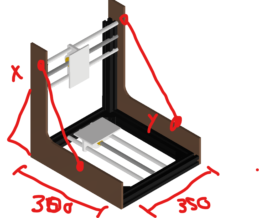
Outer Dimensions (might change based on final design) - 350mm width - 300mm depth - ? height
First Idea to Sketch
We wanted to build a use full tool for our lab and get some redundancy for our existing CNC the Carvera Makera. Machines often have issues or have downtime due to maintenance thats why it is use full to have a backup if something goes wrong with the Carvera mill. For us building a X-Y-Z computer controlled coordinate system was a completely new topic, what made this project exiting in the first place. We took our existing machines in the lab as a reference and did some research online about homemade CNC's. We checked the following:
- Carvera Makera
- Prusa MK4s printers
- Pico V2 milling machine
- Ferdis existing knowledge on CNC's
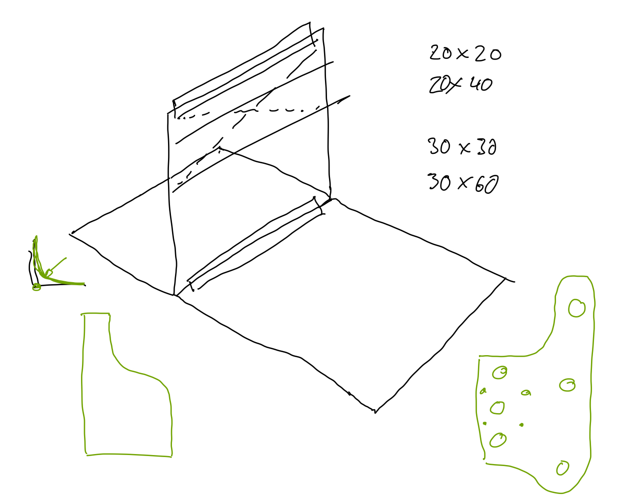
We did our Idea sketches patially in CAD software (Autodesk Inventro) and partially in 2D sketching software (Goodnotes). 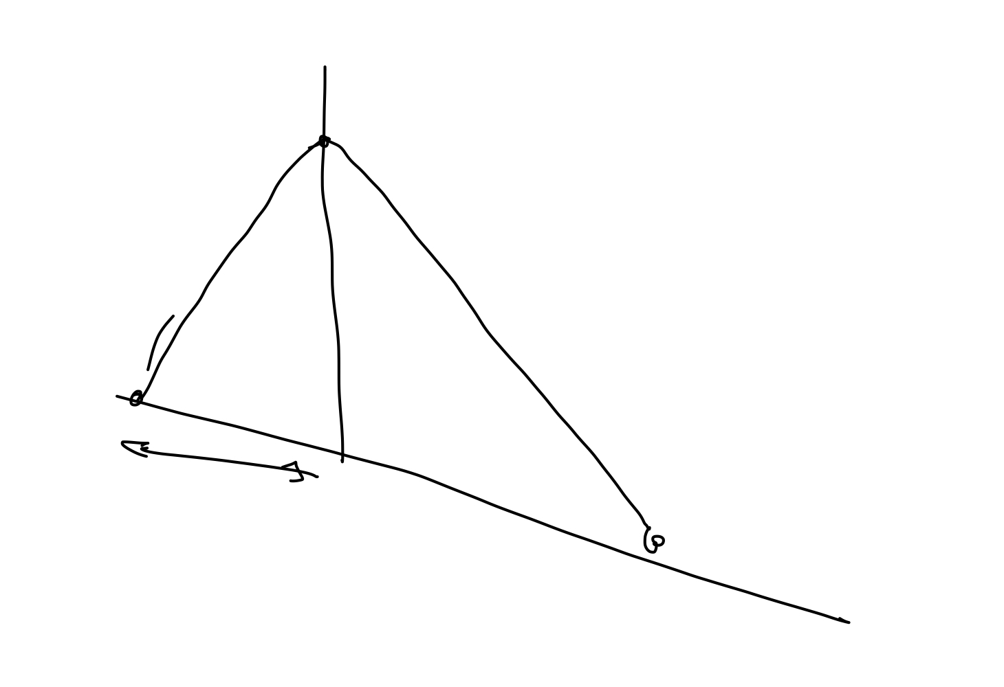
Idea Sketch to Mechanical Design
To ease the development and design we subdivided the machine in different assemblies which could be later assembled in CAD and tested after manufacturing.
3D print fitment test
Due to fitment issues after the V1 print Richard made a friction fit test which can be found in his 05 - CAD Week documentation.
Results

For 8mm rod: - model 8,125mm diameter - with a lot of force the part can be removed with a twisting motion - rod has some light rotary freedom
- model 8,1mm diameter
- assembly is only possible with force form the whole body
- no axial or rotary movement of the rod/part is possible
For 15mm bearing - model 15,25mm - solid press fit - still possible to disassemble with some force
Issues
After the friction test we were confident, that we could design all inner diameter parts with an offset of 0,15 or 0,2 mm but this did not turn out to be true.
For speed of production we printed parts parallel on tree printers: Prusa XL and two Prusa MK4S
That was not a good Idea because of tolerances. We reprinted the same part seven times on different printers and with different settings to never archive the same results

There are differences between the Prusa MK4S and the Prusa XL the reproduction accuracy is dependent on: - printer model - Input Shaper or non Input Shaper settings
... and a thousand other factors. Luckily the documentation of the fitment test 05 - CAD Week was documented enough so we could set the same settings and achieve nearly the same results.
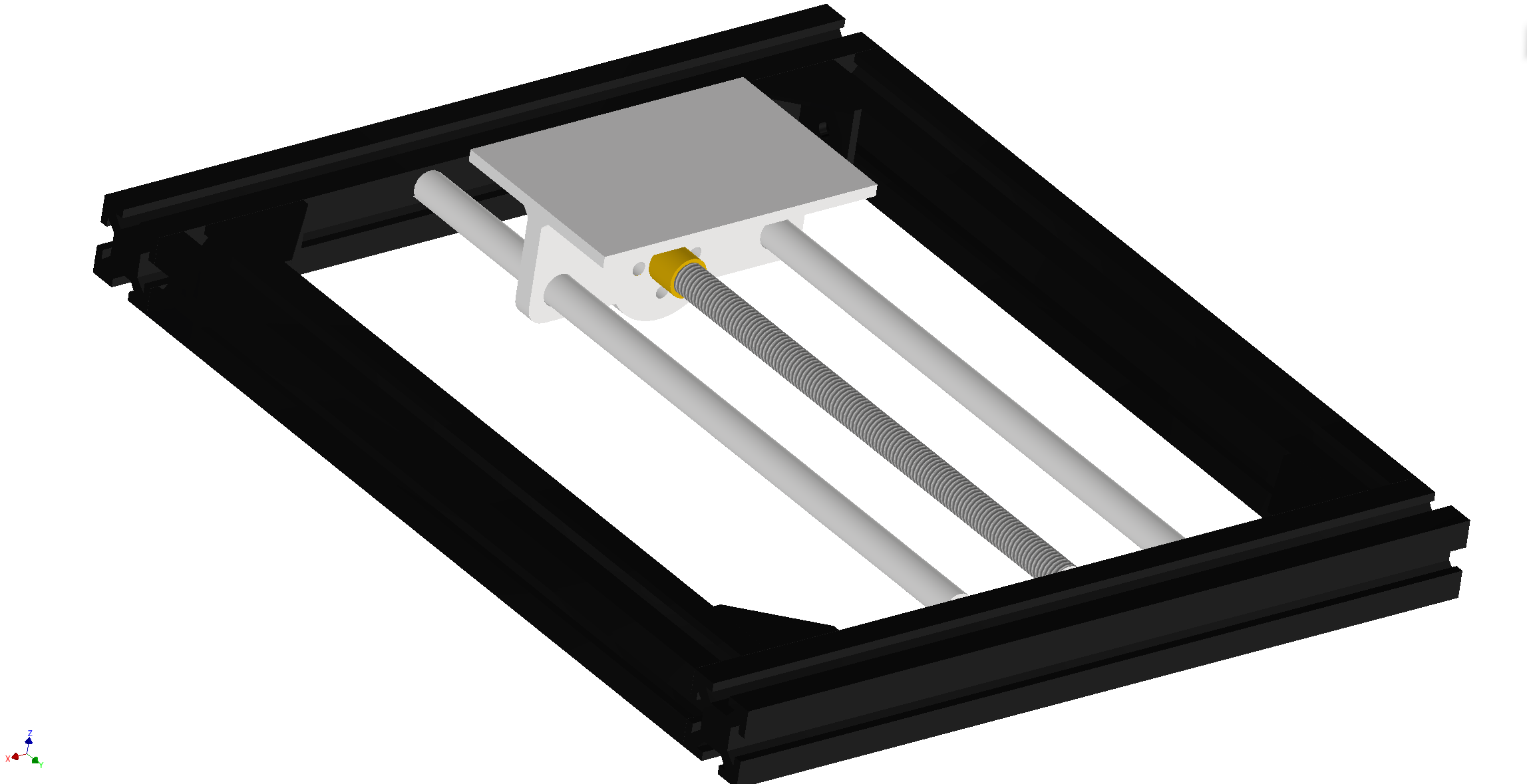
Y-Axis: (Jarni)
Design Notes - leadscrew: trapezoidal thread T8 - two T8 nuts countered for minimal backlash - new stepper + axle coupling - preferred: prusa stepper axle assembly - bushing for trapezoidal axle - guiding rods - 8mm - linear bearings - sled - 3d printed part, maybe milled aluminium - support structure for lower bed - interface plate - holes for T-Slot nuts - friction fit for guiding rods
Machine Bed
- upper bed: (waste board)
- HDF/MDF
- screw holes for fixturing?
- lower bed: steel or aluminium
- connect upper bed and lower bed with screws
X-Axis
 Iterative hardware design for the x-axis sled
Design Notes
Iterative hardware design for the x-axis sled
Design Notes
- leadscrew: trapezoidal thread T8
- two T8 nuts countered for minimal backlash
- new stepper + axle coupling
- preferred: prusa stepper axle assembly
- bushing for trapezoidal axle
- guiding rods
- 8mm
- linear bearings
- sled
- 3d printed part
- connected to z-axis
- interface plate
- holes for T-Slot nuts
- friction fit for guiding rods
V0
Issues with the V0 print - treaded inserts can't be installed due to montage clearance issues - no adjustment of the countersunk T8 nuts possible

V1
*Changes for the V1 version
- slot in nuts instead of treaded inserts
- adjusting one T8 nut is possible
Issues with the V1 print
- flexing on top and bottom reference planes (mounting points for the z-axis)
- assembly clearance to low for adding nuts

- some walls are to thin

- support incredibly hard to remove (it took 1h, spudger, drill, knife)

- use iFixit metal spudger for removal
- place support blockers in fine holes and nut slots
V2
*Changes for the V2 version
- more assembly clearance
- flipped T8 adjustment nut
- usage of paint on support structures to prevent support on the M3 nut holes

Issues with the V2 print
- flexing of the reference surface

Fix for V2 print
- add paper in between the bearings as spacer

Z-Axis: (Benedikt)
Design Notes
- manual adjustment with screws
- flexure mechanism
V1
Issues with the V1 print
- increase guiding rod diameter (current diameter after print 7,78mm for 8mm rod)
- increase distance between T8 Nut and outer wall by 1mm


- drill with 3,2mm drill for M4 screws

- design axial bearings with less friction
- current 3D printed part diameter between 14,8 and 14,9mm
- increase model diameter by 0,1mm

- design rod friction mount with less friction
- current 3D printed part diameter ~7,8mm
- print friction test
- add screws to the motor mount T8 Nut

- adjust for existing M3x30 screws
- add more material for deeper core hole or design as through hole

- incase diameter to create trough hole with large clearance fit
- allows for adjustment of bearing distance
Inventor, the CAD software we use for this project, has many powerful features that help find collisions, alignment problems, and other issues. We didn't use these features because we were in a rush. The V1 had so many problems, but still, tolerances of 3D parts cannot be predicted exactly, which is why a waste print/V1 was unavoidable.

V2
After many issues during the initial assembly process of V1 we decided to redesign many features.
Changes for V2
- double T8 nut with adjustment to reduce backlash


- thicker plates 5mm to 10mm for less flexure

- adjusting the design for fully 3D printed manufacturing
- fixing alignment issues which had which had their origin in a poorly defined sketch
- reduced leverage relative to the x-axis
- optimized space usage
Adjusting the friction fits: In V1 we printed the after endless issues and speculations on material choice, settings and different printers we landed on the following settings to get the best results

as a the filament we used Prusament Vanilla White PLA
Print settings (Prusa XL without support)

 We designed the z-axis being mount with some additional tolerance. By tightening the screws we can later adjust the alignment of the rods to avoid friction or misalignment.
Spindle and Spindle Mount
- which BLDC motor?
- brushed motor from Ferdi
- BLDC motor
- treaded inserts for the mount
- spindle collet
- high strength ABS 3d print
- mill out of aluminium
Frame
-
use existing: ITEM Profile 6 30mmx30mm (0.0.419.06)
-
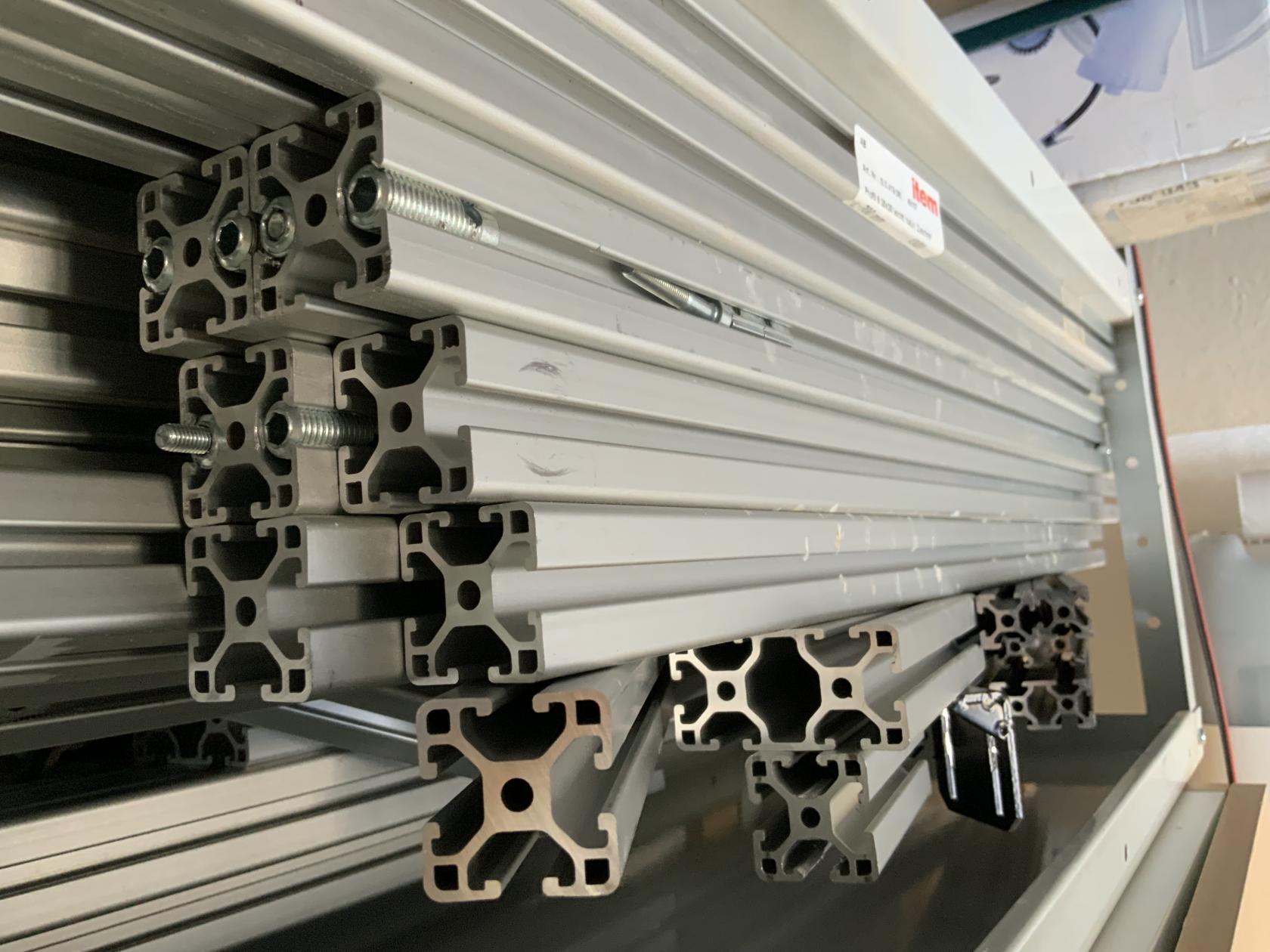
- vertical: 60*30 extrusion
- horizontal: 30*30 extrusion
- additional support by steel wires for structural rigidity
- T-Nuts

Electronics
Design Notes - human interface - housing - display - power - lab bench powersupply - cables - Motors - Stepper Motor - plugs - mechanical coupling - Spindle Motor - BLDC - BLDC driver board - Endstops - microswitches
Controller: DRV8825
adjust the current for the motors with a screwdriver and a multimeter
The alternative DRV8825 board, with increased 1/32 step mode is slightly more expensive. This is the board which we use
adjusting the steps per mm. with this calculator we calculated the neccecry steps per mm. - for T8 trapazoidal screw we should use: 1600steps per mm
RepRapDiscount Full Graphic Smart Controller
Config
We neede to set just one jumper because we had very bad noises from the motors due to stepping errors.
set one jumper for the DRV8825 type driver


Software
What is Marlin
source Marlin.org
Marlin is an open source firmware for the RepRap family of replicating rapid prototypers — popularly known as “3D printers.” Originally derived from Sprinter and grbl, Marlin became a standalone open source project on August 12, 2011 with its Github release. Marlin is licensed under the GPLv3 and is free for all applications.
- Marlin runs on a local on an AVR chips and ARM chips
- used to control 3D printer, can be modified for a cnc mill
- control-language for Marlin is a derivative of G-code
- uses a shallow queue for G-code commands sent by the host or read from SD/FD during a print job
- can run headless from an SD card
- Host software is available for several platforms, including desktop systems, Raspberry
Install Marlin
Download Marlin or I used the Git version of Marlin
Clone right Marlin version
- clone the files with
git clone https://github.com/MarlinFirmware/Marlin.git - check branch with
git statusfeedback will be most likely the beta version - change to the lts (long term support branch) with
git checkout lts-2.1.1(insert here the version number you would like to install) - check with
git statusif version is the desired stable version
Marlin Setup
The standard configuration is already made for the RAMPS board so no changes are needed. If customization is needed:
- configuration is set in the
Configuration.h- sets key configurations like machine geometry
Configuration_adv.h- optional settings for advanced and low level features
Bootscreen.hprovides the bitmap for a custom Boot ScreenStatusscreen.hprovides bitmaps to customize the Status Screen
more configuration options on the official Marlin site.
- upload and compile configuration.h and configuration.h_adv
changes in our the configuration.h
These are the changes we did to our configuration.h file to enable the hardware. Everything else was left as default.
uncomment:
- #define CUSTOM_MACHINE_NAME "CNC mill JarBeRi"
- enables machine name on the homescreen
- #define REPRAP_DISCOUNT_FULL_GRAPHIC_SMART_CONTROLLER
- enables communication with the display module we use
To adjust the software to our real world design and mechanical behavior we need to do some changes:
- change steps per mm:

- change motor driver:

- z max position:


change baudrate:
#define BAUDRATE 250000
Flash Marlin to the Board
Go to the Marlin folder in the Marlin folder and open the Marlin.ino in the Arduino IDE.
- Select the Arduino Mega 2560 board under
Tools->Board - Select the usb serial port under
Tools->Port - upload the code to the Mega 2560
Pronterface (Interface with the Marlin software on the board)
Proterface is the desktop software which can send G-Code commands to the ATmega board. These commands then get interpreted by the Marlin software and executed by the stepper motors and spindle
- printcore.py is a library that makes writing RepRap hosts easy
- pronsole.py is an interactive command-line host with tab-completion goodness
- pronterface.py is a graphical host with the same functionality as pronsole
Setup
- Turn on the main powersupply
- Connect to the board with an USB cable
- Select:
- Port: use the same Port as in the Arduino IDE
- Baud: use the same Port as in the Arduino IDE
- is defined in the
configuration.hfile under#define BAUDRATE 250000
- is defined in the
-
press
Connectbutton -
Home, execute G-Code commands
Useful G-Code commands
G91: Set to Relative Positioning
© 2025 Richard Draxler – Creative Commons Attribution Non Commercial
Source code hosted at gitlab.fabcloud.org