2. Computer-Aided Design (S0 state)
view Checklists
*Checklist: personal*- [x] DeepL check spelling, grammar
- [ ] GPTcheck for better markdown
- [x] repair file links, replace .png -> .jpg; .mov -> .mp4, .webp
- [ ] compress all files before push
- [x] use boxes.py in conjunction with Incscape
- [ ] 2D cad: LibreCad, export as svg -> Inkscape convert to .dxf R12 for the laser cutter
- [ ] use and document cuddle.xyz
- [x] fix links to pictures
- [x] finish and document image pipeline
- [x] document compressing videos
*Checklist: Nueval: Student's checklist*
- [x] Modelled experimental objects/part of a possible project in 2D and 3D software
- [x] Shown how you did it with words/images/screenshots
- [x] Documented how you compressed your image and video files
- [x] Included your original design
3D CAD Software
Shapr3D
The CAD tool I used this week is Shapr3D on my iPad because I enjoy designing 3D files with a pen and my fingertips.
For the CAD Design Week, I decided to continue with my final project.
Final Project - LUEDO
LUEDO already exists as a proof-of-concept prototype, but it has one major problem:
The lamp doesn't reliably align with the magnetic mount.
It snaps into place, but is usually off by a few millimeters, which neglects the main functionality of automatically changing the color of the emitted light.
Current state of the LUEDO housing:


To improve the alignment, I had the idea to support the magnetic alignment with a mechanical component.
That's why I redesigned the mount that will later be connected to the vehicle.
The new version of the mount has slopes on the sides to guide the lamp towards the magnet and ensure a fixed position.
To model the improved mounting system, I decided to create a mockup of the lamp, which reduces the work to implement the system in the housing, which is quite complicated.
The housing includes two pieces of a metal ring to which the magnets from the charger/monitor snap and a small alignment strip to lock the rotation.
For the following mockup, I started with the existing mount and added some bevels and radii.

After completing the mount, I subtracted the mount from the purple pebble shape to create a mechanical prototype that could later be printed during 3D Printing Week.

After subtracting the shapes from each other, I had to clean up the model.


Many times I failed to subtract the Boolean operation because I was trying to manually sweep a fillet on an edge.
The idea was to redefine the shape of the fillet as an asymmetric shape to improve the alignment capabilities of the shape.
After getting errors, I decided to just go with a normal fillet.

I added 0.1mm of clearance on each side, giving me a total of 0.2mm to move the mount.

The final resulting shape not only has the advantage of better alignment, but it also increases the magnetic surface area, resulting in better magnetic adhesion.
The downside of the redesigned mounting system is that it reduces the internal volume of the lamp itself.
Another disadvantage is the less streamlined design of the outer shell, which already annoys me.
This can be seen in detail when the part is printed.


CAD Files
Here are the .stl files for the Mount.stl and Mockup.stl
Fusion 360
2025-04-06 The here described part is used for 7. Computer-Controlled Cutting
I have worked before in Inventor which is as well form Autodesk an very similar to Fusion360, but for the integrated CAM software I decided to give it a try.
Parametric Designing
Creating parametric designs in Fusion is very easy because sketches remain attached to the created volume - you can go back in the history of a part, which is very convenient for changing the thickness of a slot in this fitting cam to define a plug fit, for example.
The Fusion interface is relatively intuitive and comparable to other mechanical design CAD software. Creating sketches is straightforward, and assigning dimensions as functions of another dimension is also easy.
In the example shown, the distance between the various slots will always remain at the assigned value, while the actual slot size can be determined manually for each slot.
Dogbones for CNC machining
CNC milling is always done with a rotary bit, which does not allow us to create rectangular internal corners. For assembly purposes it is necessary to create so-called dogbones, which cut away more material in the corner to give the possibility to insert rectangular parts later. At first I tried to model the dogbone structure in the sketch, which is possible, but tedious if you want to do it for every corner of your design.

So I installed a Dogbone plugin for Fusion from GitHub. I use this tutorial to set it up quickly. This Fusion plug-in creates a dogbone, which is similar to a fillet-style edge manipulation. While it is fairly easy to use, it creates a ton of sketches and construction planes, which makes me a little nervous, but I will see how it turns out later in the design process.


This is the end result: a comb for fitting tests in multiplex.

CAD Files
18mm_multiplex_comb v3.f3d
18mm_multiplex_comb v3.stl
2D CAD Software
Boxes.py
For the 2D part I decided to use some tools that are off the beaten path. Ferdi recommended to my to check out some of the box generators and there are plenty of them available. I chose Boxes.py - by Hackspace Bamberg


This is a mockup for the charging station which I will use for my final project. The existing mockup is 3D printed, has fitting problems in the corners (because it was not generated automatically) and is a bit ugly. Time to redesign the charging station with the right tools and materials!
I started with the simple Console
Here are the parameters that I used:

I took the kerf setting from our Week03 Computer-Controlled Cutting Group Assignment page. Kerf: 0.1mm
Boxes.py has the following export formats: - dxf - gcode - lbrn2 - pdf - plt - ps - svg - svg_ponoko
Inkscape
I choose .dxf and imported the file into Inkscape
Inkscape is a powerful, free design tool which can handle vector graphics.

I quickly added a couple of circles to embed the Qi2 charging pucks into the front plate.

Generally the editing a manufacturing design in Inkscape is probably not the best idea, but at least I tried.
Media Software
Imagepipeline (capturing and compressing images)
Screenshots
To insert the screenshots I decided to use the "Paste Image by mushan" plugin for VSCodium, which I documented in Week 1. already.
Gimp/Bimp
Install Gimp/Bimp
Ferdinand gave us a couple of classes.One of them was how to use Gimp and the Bimp - Batch Image Manipulation plugin, but he didn't show us how to install the plugin, which is absolutely fine. So I did my own research how to install plugins in Gimp. The problem was, that I couldn't get the plugin to work. After half an hour of research I found out that I installed the plugin correctly, but there seems to be a bug with newer Gimp versions and the plugin on MacOS. I deleted the current Gimp version and the Bimp plugin from the Plugins folder, and then installed Gimp version 2.10.22 (revision 3) with the current Bimp plugin version. And it worked!

The installed plugins are located in:
/Users/Username/Library/Application Support/GIMP/2.10/plug-ins
During the Bimp installation I read the readme.txt and it said ...

Some might say RTFM!
Use Bimp to compress and modify images
Open Gimp and go to File -> Batch Image Manipulation. Now you can add your files and choose an output folder. In the "Manipulation set" section add your steps for the modification pipeline.

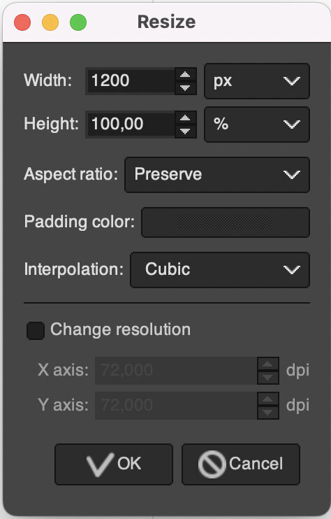
My default for now became first resize to 1200px with while preserving the aspect ratio.

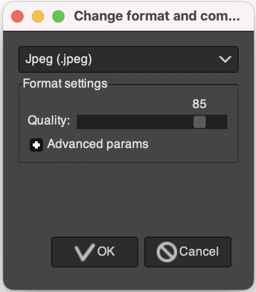
In the second step I take the 'Change format and compression' option to convert all images to .jpeg files (the actual file gets the .jpg filename) and compress them to a quality of 85%.

After compression the images are between 50 and 200kb each.
Video pipeline (capturing and compressing videos)
Apple Photos
I use my built-in software to crop, rotate, or color correct my videos.
Handbreak
Handbrake is a GUI interface for the ffmpeg video compression software. It is free, open source and easy to install.
Here are the presets (Very Fast 1080p30/no audio) which I use to compress my videos.

ffmpeg
I installed ffmpeg using the terminal and brew.
brew install ffmpeg- apparently there were multiple dependencies for ffmpeg

ffmpeg -versionto check if ffmpeg is installed
here are the necessary commands for ffmpeg.
What I learned form week02
- compressing pictures in telegram and cropping them later is way to slow!
- Inkscape is a powerful tool for many applications
© 2025 Richard Draxler – Creative Commons Attribution Non Commercial
Source code hosted at gitlab.fabcloud.org