Week 15: System Integration
Table of Contents
This week, the Task was to continue working on the final project, including programming, design, electronics, and assembly. In particular, it should be considered how to integrate all components of the system in a nice way.
Digitial Files
The digital files for this assignment are the ones provided on the final project page.
This Week’s Tasks
- Design and document the system integration for your final project
This Week’s Lecture
This week’s lecture covered what could go wrong when designing a product from an engineer’s perspective and how to circumvent that. Topics covered were usability, design for machining, documentation tools accompanying the design process (OSH and a KiCad BOM extension). We were advised to design nice packaging for our product (considering surface finish, look & feel, shape, …) and to consider the routing and mounting of wires. Basic quality assurance methods were highlighted (shaking, burn-in, power cycling, etc.). as an example assignment, I looked at the one by Edwin Dertien. More notes on this can be found in my lecture notes.
System Design
An important part of music subculture events is not only the music, but also visual art as well as the light scenery. My idea was to make a wearable, wireless interface in form of a glove or a bracelet including several sensors (accelerometers, vector magnetometer, etc.). The device could then send control signals to a music or light component, e.g. via OSC or MIDI. This would enable light operators, musicians and visual artists to change parameters in their setup while moving and/or being away from their personal computer.


Programming
Retrieving Data From BNO085 Sensor
In the below video it can be seen how the microcontroller reads the rotation vector data from the sensor and outputs them to the serial console.
For reading the rotational position, the BNO085 sensor integrated with the corresponding Adafruit breakout board is used. In the input-devices week (9), I read about how to use that component and how to read data from it using the provided SH2 interface.
While I used the Arduino framework in the input-devices week (9), I wanted to re-implement the remote firmware using the ESP-IDF to be consistent with the dongle firmware. The dongle firmware needed to be implemented using the ESP-IDF due to the availability of USB libraries. However, I faced reliability issues with the SPI interface for the BNO085 sensor using the corresponding library for the ESP-IDF. The problem was that the initialization of the sensor was only successful sometimes. Most of the time it was not. My assumption is that during the initialization some specific pins of the ESP32S3 got pulled low which led to misconfigurations. Due to time constraints I decided not to try finding an explanation, but to find a more simple solution.

- Using another micro-controller for the remote which is capable of some form of wireless communication with a dongle.
- Programming the remote with the Arduino framework talking to the sensor using SPI.
- Programming the remote with the Arduino framework talking to the sensor using I2C and check if it is also unreliable in my case.
The first option was not possible due to the time left. The second option, I assumed, could have lead to the same issue as described above if the problem really was the pin configuration. I decided to try communicating with the sensor using I2C. Only the library available for the Arduino framework implemented I2C communication, so I switched to use that for the remote firmware. The dongle I would keep programming using the ESP-IDF due to the USB-MIDI support, which again was not available in the Arduino environment. This was reasonable, because I did not know which kind of reliability issues existed with the I2C communication. If only some information had not been transmitted, this would have been fine for the application. Fortunately, no issues were experienced with the resulting setup it was not present when the Arduino environment with the other Adafruit BNO085 library which supported I2C communication was used.
For reading the rotation vector data, the virtual sensor GYRO_INTEGRATED_RV is used. The reason for this is explained in the input-devices week (9) (short: low but high-enough accuracy for high-frequency of updates). Besides the rotation vector, the virtual sensor for a tap event (occurring when tapping onto the remote) is read and processed as well. The sensor data is read and processed using a timer to be able to conveniently control the frequency of that operation. Processing of the sensor data happens inside handleGyroReport and handleTapReport.
Below you can see the code snippets for the communication between remote controller and sensor relevant to understand the rough control flow. The name of the file is remote.cpp.
  1#include <Arduino.h>
  2#include <TimerEvent.h>
  3#include <Adafruit_BNO08x.h>
  4#include <cstddef>
  5
  6// ...
  7
  8#define PERIOD 5 /* Period to operate timers on in ms. */
  9
 10// Set up timers.
 11TimerEvent timerReadSensorData;
 12
 13// ...
 14
 15// Configure BNO08x.
 16//#define BNO08X_CS 10
 17//#define BNO08X_INT 9
 18//
 19// ..configure using I2C
 20#define BNO08X_RESET -1
 21//
 22Adafruit_BNO08x  bno08x(BNO08X_RESET);
 23sh2_SensorValue_t sensorValue;
 24//
 25typedef struct  {
 26  float yaw;
 27  float pitch;
 28  float roll;
 29} RVecEuler_t;
 30//
 31typedef struct  {
 32  uint8_t pitch;
 33  uint8_t roll;
 34} RVecMIDI_t;
 35//
 36RVecEuler_t rvEuler;
 37RVecMIDI_t rvMIDI;
 38
 39// Declare functions.
 40void setup();
 41void loop();
 42void setReports();
 43void readSensorsSendMIDI();
 44void quaternionToEuler(float qr, float qi, float qj, float qk, RVecEuler_t* ypr, bool degrees);
 45void eulerToMIDI(RVecEuler_t rvEuler, RVecMIDI_t* rvMIDI);
 46void handleGyroReport(MIDIData_t* data);
 47void handleTapReport(MIDIData_t* data);
 48
 49
 50
 51void setup()
 52{
 53  Serial.begin(115200);
 54  //
 55  // Without this delay, the communication seemed not to be working. The reason is yet to be found out.
 56  delay (100);
 57  Serial.println("Initializing...");
 58
 59  // ...
 60
 61  // Try to initialize.
 62  if (!bno08x.begin_I2C()) {
 63    Serial.println("Failed to find BNO08x chip.");
 64    while (1) { delay(10); }
 65  }
 66  Serial.println("BNO08x Found.");
 67
 68  for (int n = 0; n < bno08x.prodIds.numEntries; n++) {
 69    Serial.print("Part ");
 70    Serial.print(bno08x.prodIds.entry[n].swPartNumber);
 71    Serial.print(": Version :");
 72    Serial.print(bno08x.prodIds.entry[n].swVersionMajor);
 73    Serial.print(".");
 74    Serial.print(bno08x.prodIds.entry[n].swVersionMinor);
 75    Serial.print(".");
 76    Serial.print(bno08x.prodIds.entry[n].swVersionPatch);
 77    Serial.print(" Build ");
 78    Serial.println(bno08x.prodIds.entry[n].swBuildNumber);
 79  }
 80
 81  setReports();
 82
 83  timerReadSensorData.set(PERIOD, readSensorsSendMIDI);
 84
 85  Serial.println("Reading events");
 86  delay(100);
 87}
 88
 89
 90
 91void loop()
 92{
 93  timerReadSensorData.update();
 94}
 95
 96
 97
 98void setReports()
 99{
100  Serial.println("Setting desired reports");
101  if (! bno08x.enableReport(SH2_GYRO_INTEGRATED_RV, PERIOD * 1000)) {
102    Serial.println("Could not enable gyroscope report.");
103  }
104  if (! bno08x.enableReport(SH2_TAP_DETECTOR, PERIOD * 500)) {
105    Serial.println("Could not enable tap report.");
106  }
107}
108
109
110
111void readSensorsSendMIDI()
112{
113  MIDIData_t data;
114
115  data.pitch = MIDI_NONE;
116  data.roll = MIDI_NONE;
117  data.tap = MIDI_NONE;
118  data.tap_double = MIDI_NONE;
119
120  if (bno08x.wasReset()) {
121    Serial.print("Sensor was reset.");
122    setReports();
123  }
124
125  if (! bno08x.getSensorEvent(&sensorValue)) {
126    return;
127  }
128
129  switch (sensorValue.sensorId) {
130    case SH2_GYRO_INTEGRATED_RV:
131      handleGyroReport(&data);
132      break;
133    case SH2_TAP_DETECTOR: {
134      handleTapReport(&data);
135    }
136  }
137
138  // `data` now contains all relevant
139  // information retrieved from the sensor
140  // ready for further processing.
141  // ...
142}
Below you see all utility functions from the same file. The two blocks are separated for readability.
 1void handleGyroReport(MIDIData_t* data)
 2{
 3  sh2_GyroIntegratedRV_t* rotational_vector = &sensorValue.un.gyroIntegratedRV;
 4
 5  quaternionToEuler(
 6    sensorValue.un.gyroIntegratedRV.real,
 7    sensorValue.un.gyroIntegratedRV.i,
 8    sensorValue.un.gyroIntegratedRV.j,
 9    sensorValue.un.gyroIntegratedRV.k,
10    &rvEuler,
11    true
12  );
13
14  eulerToMIDI(rvEuler, &rvMIDI);
15
16  // Write all received data (from multiple possible sources) into the packet to be sent.
17  data->pitch = rvMIDI.pitch;
18  data->roll = rvMIDI.roll;
19
20  #ifdef DEBUG_GYRO
21  Serial.print("WRIST:");
22  Serial.print("\tPitch: ");
23  Serial.print(data->pitch);
24  Serial.print("\tRoll: ");
25  Serial.println(data->roll);
26  #endif
27}
28
29
30
31void handleTapReport(MIDIData_t* data)
32{
33  sh2_TapDetector_t detector = sensorValue.un.tapDetector;
34  // The flag consists of several bits that indicate different kind of taps. Details are to be read in the SH2 specification.
35  bool tap_x_direction = detector.flags & (1 << 0);
36  bool tap_y_direction = detector.flags & (1 << 2);
37  bool tap_z_direction = detector.flags & (1 << 4);
38  bool tap = tap_x_direction || tap_y_direction || tap_z_direction;
39
40  bool tap_double = detector.flags & (1 << 6);
41
42  if (tap) {
43    data->tap = 1;
44  }
45  if (tap_double) {
46    data->tap_double = 1;
47  }
48
49  #ifdef DEBUG_TAP
50  if (tap || tap_double) {
51    Serial.print("WRIST:");
52    Serial.print("\tTap: ");
53    Serial.print(data->tap);
54    Serial.print("\tTap double: ");
55    Serial.print(data->tap_double);
56    Serial.println();
57  }
58  #endif
59}
60
61
62
63void quaternionToEuler(float qr, float qi, float qj, float qk, RVecEuler_t* ypr, bool degrees)
64{
65
66  float sqr = sq(qr);
67  float sqi = sq(qi);
68  float sqj = sq(qj);
69  float sqk = sq(qk);
70
71  ypr->yaw = atan2(2.0 * (qi * qj + qk * qr), (sqi - sqj - sqk + sqr));
72  ypr->pitch = asin(-2.0 * (qi * qk - qj * qr) / (sqi + sqj + sqk + sqr));
73  ypr->roll = atan2(2.0 * (qj * qk + qi * qr), (-sqi - sqj + sqk + sqr));
74
75  if (degrees) {
76    ypr->yaw *= RAD_TO_DEG;
77    ypr->pitch *= RAD_TO_DEG;
78    ypr->roll *= RAD_TO_DEG;
79  }
80}
81
82
83
84void eulerToMIDI(RVecEuler_t rvEuler, RVecMIDI_t* rvMIDI)
85{
86  // rvEuler.roll ranges from -180 to +180. -/+180 is the position where the sensor is held upside-down. It is one single position. The value is 0 if the sensor is facing up. For easier processing and easier use, it was a design decision to only want to care how much the sensor is rolled, regardless if the roll is clock-wise or counter-clock-wise. This is why the absolute value is taken. The result ranges from 0 to 180. This then needs to be mapped to the MIDI data range. `* 181 >> 8` approximates `* 127 / 180`. To do division using bit shifting, we need to be able to divide by a power of 2. The fraction therefore needs to be expanded by ((255/180) / (255/180)) so that there is a power of 2 (i.e. 255) in the denominator. The division by 255 can then be expressed as `>> 8`. Floating-point multiplications are faster to be done than floating-point divisions if an FPU is used, which is the case for the ESP32S3.
87  uint8_t roll = (uint8_t)abs(rvEuler.roll) * 180 >> 8;
88  // rvEuler.pitch ranges from -90 (all the way up) to +90 (all the way down). The direction of the "front" of the object is determined by the yaw, so that is not taken into account for the pitch. The MIDI value should be 0 when the object faces down, and it should have full value, when the object faces all the way up.
89  uint8_t pitch = (uint8_t)abs(rvEuler.pitch + 90) * 180 >> 8;
90
91  rvMIDI->pitch = pitch;
92  rvMIDI->roll = roll;
93}
Communication Between Remote & Dongle
For data transmission from remote to dongle, ESP-NOW was chosen. I already worked with it in the networking-and-communication week (11) where a fellow student, Niclas, and I set up two ESP32-boards to communicate with each other.
I discussed ESP-NOW already in the networking-and-communication week (11). ESP-NOW is a communication protocol defined by Espressif. It operates on top of the data link layer, providing a simple communication method that does not require additional layers such as network or transport layers. One only needs to specify a MAC address of the peer. No connection setup is necessary. This enables fast communication. For further reference, one can check the official website as well as the API documentation. A protocol analysis can be found here.
When compared to Bluetooth (BT), ESP-NOW has higher power consumption but significantly lower latency, following the paper Comparative Performance Study of ESP-NOW, Wi-Fi, Bluetooth Protocols based on Range, Transmission Speed, Latency, Energy Usage and Barrier Resistance by Dania Eridani et al.. Alternatively, one could have experimented more with specific Bluetooth profiles for low latency and check if there are any differences. For this project, however, I decided to prefer ESP-NOW over Bluetooth, because from the paper it is known to be well-suited for responsive applications and it is easy to set up.
Below a video can be seen of the remote sending sensor data to the dongle. Afterwards, the code will be explained.
The sensor data are packed into the following struct (defined in packet_format.h).
1// Describing the format of the packet being sent from the remote to the dongle.
2typedef struct __attribute__((packed)) {
3    uint8_t pitch;
4    uint8_t roll;
5    uint8_t tap;
6    uint8_t tap_double;
7} MIDIData_t;
8
9#define MIDI_NONE 255 // If an entry in the MIDIData struct has this value, it is to be ignored.
The struct is packed. That means that the values are written directly after each other in the memory and there is no padding added. This is explained in this forum post. I did this to have complete control over how the structure is assembled on bit-level. The reason for that is that Niclas and I had issues with correctly casting received packets. I do not know if the bit-level positions of the values in the struct were playing a role or if the problem was something else, but changing the struct to be packed solved the problem.
The remote firmware was extended to send the MIDIData_t structure via ESP-NOW. I used the library QuickEspNow for that purpose.
 1// ...
 2
 3#include <WiFi.h>
 4#include <esp_wifi.h>
 5#include <QuickEspNow.h>
 6
 7#include "packet_format.h"
 8
 9// ...
10
11// ESP-NOW: add receiver (dongle) MAC address.
12static uint8_t receiver[] = { 0x64, 0xE8, 0x33, 0x51, 0x30, 0x48 };
13
14// ...
15
16void setup()
17{
18    // ...
19
20    // Initialize ESP-NOW
21    WiFi.mode(WIFI_MODE_STA);
22    WiFi.disconnect(false, true);
23    quickEspNow.begin(1);
24
25    // ...
26}
27
28void loop()
29{
30    // ...
31}
32
33void setReports()
34{
35    // ...
36}
37
38void readSensorsSendMIDI()
39{
40    // process data from sensor (as shown in above subsection)
41    // ...
42
43    quickEspNow.send(receiver, (uint8_t*)&data, sizeof(data));
44}
45
46// ...
The dongle was programmed to receive those packets. Below, the dongle code including only the parts necessary for ESP-NOW is shown. To view the header, please refer to the original files.
During system setup, a callback function espnow_recv_cb is set in case of a packet being received. This callback function only takes care of receiving the packet and forwarding it to be processed by another FreeRTOS task: espnow_listening. This is done by writing the data into a static MIDIData_t structure. This structure is persistent over the scope of the callback due to the static keyword. The listening task is noticed about the presence of a new packet by adding an element to the s_recv_queue. Until this queue is empty, the listening task processes the value that is currently stored in the recv_packet structure. It is good practice to keep callbacks and interrupts as small as possible. Otherwise it could happen that not every event is processed correctly due to blocking interrupt procedures.
 1#include "dongle.h"
 2
 3// Global variables.
 4static QueueHandle_t s_recv_queue = NULL;
 5
 6// ...
 7
 8// Declare functions.
 9static void espnow_init(void);
10static void espnow_recv_cb(const esp_now_recv_info_t *recv_info, const uint8_t *data, int len);
11static void espnow_listening(void *p);
12
13// ...
14
15void app_main(void)
16{
17    // ...
18
19    ESP_LOGI(TAG, "Initializing ESP-NOW...");
20    s_recv_queue = xQueueCreate(16, sizeof(MIDIData_t));
21    assert(s_recv_queue);
22    BaseType_t err = xTaskCreate(espnow_listening, "recv_task", 8192, NULL, 4, NULL);
23    assert(err == pdPASS);
24
25    espnow_init();
26
27
28    while(1){
29        vTaskDelay(PERIOD);
30    }
31}
32
33static void espnow_init(void)
34{
35    const wifi_init_config_t cfg = WIFI_INIT_CONFIG_DEFAULT();
36    esp_err_t ret = nvs_flash_init();
37    if (ret == ESP_ERR_NVS_NO_FREE_PAGES || ret == ESP_ERR_NVS_NEW_VERSION_FOUND) {
38        ESP_ERROR_CHECK( nvs_flash_erase() );
39        ret = nvs_flash_init();
40    }
41    ESP_ERROR_CHECK( ret );
42    ESP_ERROR_CHECK( esp_netif_init());
43    ESP_ERROR_CHECK( esp_event_loop_create_default() );
44    ESP_ERROR_CHECK( esp_wifi_init(&cfg) );
45    ESP_ERROR_CHECK( esp_wifi_set_storage(WIFI_STORAGE_RAM) );
46    ESP_ERROR_CHECK( esp_wifi_set_mode(MY_ESPNOW_WIFI_MODE) );
47    ESP_ERROR_CHECK( esp_wifi_start() );
48#if MY_ESPNOW_ENABLE_LONG_RANGE
49    ESP_ERROR_CHECK( esp_wifi_set_protocol(MY_ESPNOW_WIFI_IF, WIFI_PROTOCOL_11B|WIFI_PROTOCOL_11G|WIFI_PROTOCOL_11N|WIFI_PROTOCOL_LR) );
50#endif
51    ESP_ERROR_CHECK( esp_now_init() );
52    ESP_ERROR_CHECK( esp_now_register_recv_cb(espnow_recv_cb) );
53}
54
55static void espnow_recv_cb(const esp_now_recv_info_t *recv_info, const uint8_t *data, int len)
56{
57    static MIDIData_t recv_packet;
58
59    if(len != sizeof(MIDIData_t))
60    {
61        ESP_LOGE(TAG, "Unexpected data length: %d != %u", len, sizeof(MIDIData_t));
62        return;
63    }
64
65    memcpy(&recv_packet, data, len);
66    if (xQueueSend(s_recv_queue, &recv_packet, 0) != pdTRUE) {
67        ESP_LOGW(TAG, "Queue full, discarded");
68        return;
69    }
70}
71
72static void espnow_listening(void *p)
73{
74    static MIDIData_t recv_packet;
75
76    ESP_LOGI(TAG, "Listening");
77    for(;;)
78    {
79        if(xQueueReceive(s_recv_queue, &recv_packet, portMAX_DELAY) != pdTRUE)
80        {
81            continue;
82        }
83
84        // Send the received data in form of a MIDI message.
85        // ...
86    }
87}
Dongle Converting Data to MIDI
Finally, I designed MIDI behavior where pitch controls CC messages (only when above a threshold) and roll triggers NOTE_ON/OFF messages. The dongle could then be registered as a MIDI controller and mapped in an arbitrary digital audio workstation for controlling filter cut-off, pitch, etc.
The below video shows the controller operating the cutoff-value of a low-pass filter which again is applied to a distorted sine oscillator. Note that the video was recorded when I still implemented the roll as a switch (NOTE_ON/NOTE_OFF) parameter. In the meantime I changed the code to handle both the pitch and the roll as continuous CC values. Both configurations have their up- and downsides and depend on the application.
I programmed the dongle to process the pitch and roll as generic CC messages. Furthermore, the remote only sends MIDI data for the gyroscope’s pitch/roll if the value is larger than 20. The reason is how MIDI controllers are mapped to software parameters. It is done by telling the software to listen to any MIDI input and then only change the one knob to be mapped to a parameter. To be able to either send pitch CC or roll CC messages, the user needs to be able to send only one type of message at a time. With the current implementation the user just needs to hold the controller so the front faces down to deactivate pitch values being sent. This, however, is not optimal, since it is not possible for the user to send values below 20. One could, however adapt the range of the CC value so that the current value 20 would correspond to a new value of 1. The code can be seen below. Again, for the dongle.h file, please refer to the original files.
  1#include "dongle.h"
  2
  3// Global variables.
  4// ...
  5static bool midi_roll_last_msg_was_note_on = false;
  6static bool midi_tap_last_msg_was_note_on = false;
  7
  8// Declare functions.
  9// ...
 10void midi_send_data(MIDIData_t data);
 11static void midi_task_read(void *arg);
 12
 13void app_main(void)
 14{
 15
 16    #ifdef USB
 17    //  = = = = = = = = = = = = = = =   //
 18    ESP_LOGI(TAG, "Initializing USB...");
 19    tinyusb_config_t const tusb_cfg = {
 20        .device_descriptor = NULL, // If device_descriptor is NULL, tinyusb_driver_install() will use Kconfig
 21        .string_descriptor = s_str_desc,
 22        .string_descriptor_count = sizeof(s_str_desc) / sizeof(s_str_desc[0]),
 23        .external_phy = false,
 24#if (TUD_OPT_HIGH_SPEED)
 25        .fs_configuration_descriptor = s_midi_cfg_desc, // HID configuration descriptor for full-speed and high-speed are the same
 26        .hs_configuration_descriptor = s_midi_hs_cfg_desc,
 27        .qualifier_descriptor = NULL,
 28#else
 29        .configuration_descriptor = s_midi_cfg_desc,
 30#endif // TUD_OPT_HIGH_SPEED
 31    };
 32    ESP_ERROR_CHECK(tinyusb_driver_install(&tusb_cfg));
 33
 34    //  = = = = = = = = = = = = = = =   //
 35    ESP_LOGI(TAG, "Initializing MIDI reading task...");
 36    // The MIDI interface always creates input and output port/jack descriptors regardless of these being used or not. Therefore incoming traffic should be read (possibly just discarded) to avoid the sender blocking in IO.
 37    xTaskCreate(midi_task_read, "midi_task_read", 4 * 1024, NULL, 5, NULL);
 38    #endif
 39
 40    // ...
 41
 42    while(1){
 43        vTaskDelay(PERIOD);
 44    }
 45}
 46
 47static void espnow_init(void)
 48{
 49    // ...
 50}
 51
 52static void espnow_recv_cb(const esp_now_recv_info_t *recv_info, const uint8_t *data, int len)
 53{
 54    // ...
 55}
 56
 57static void espnow_listening(void *p)
 58{
 59    static MIDIData_t recv_packet;
 60
 61    ESP_LOGI(TAG, "Listening");
 62    for(;;)
 63    {
 64        if(xQueueReceive(s_recv_queue, &recv_packet, portMAX_DELAY) != pdTRUE)
 65        {
 66            continue;
 67        }
 68
 69        // Process the packet.
 70        midi_send_data(recv_packet);
 71    }
 72}
 73
 74void midi_send_data(MIDIData_t data)
 75{
 76    #ifdef USB
 77    // Create MIDI packets.
 78    if (tud_midi_mounted()) {
 79    #endif
 80        if (data.tap != MIDI_NONE) {
 81            uint8_t note_tap[3] = {
 82                midi_tap_last_msg_was_note_on ? NOTE_OFF : NOTE_ON | CHANNEL,
 83                MIDI_TAP_NOTE_NUM,
 84                120, // Velocity
 85            };
 86            midi_tap_last_msg_was_note_on = !midi_tap_last_msg_was_note_on;
 87            #ifdef USB
 88            tud_midi_stream_write(CABLE_NUM, note_tap, 3);
 89            #endif
 90        }
 91
 92        if (data.pitch != MIDI_NONE) {
 93            // Use pitch & roll as knobs.
 94            // ..only activate if certain threshold is exceeded.
 95            uint8_t pitch_inv = 127 - data.pitch;
 96            const int pitch_thresh = 20;
 97            if (pitch_inv > pitch_thresh){
 98                uint8_t cc_msg_pitch[3] = {
 99                    CONTROL_CHANGE | CHANNEL,
100                    MIDI_PITCH_CONTROL_NUM, // Index. Also known as "control number". CC 16-19 indicates a "generic control".
101                    pitch_inv, // Data. Also known as "control value". Encodes the "position" of the "knob".
102                };
103                #ifdef USB
104                tud_midi_stream_write(CABLE_NUM, cc_msg_pitch, 3);
105                #endif
106            }
107        }
108
109        if (data.roll != MIDI_NONE) {
110            // ..same for roll
111            const int roll_thresh = 20;
112            if (data.roll > roll_thresh){
113                uint8_t cc_msg_roll[3] = {
114                    CONTROL_CHANGE | CHANNEL,
115                    MIDI_ROLL_CONTROL_NUM, // Index. Also known as "control number". CC 16-19 indicates a "generic control".
116                    data.roll, // Data. Also known as "control value". Encodes the "position" of the "knob".
117                };
118                #ifdef USB
119                tud_midi_stream_write(CABLE_NUM, cc_msg_roll, 3);
120                #endif
121            }
122        }
123    #ifdef USB
124    }
125    #endif
126
127    ESP_LOGE(TAG, "Pitch: %d,\tRoll: %d", data.pitch, data.roll);
128}
129
130static void midi_task_read(void *arg)
131{
132    uint8_t packet[4];
133    bool read = false;
134    for (;;) {
135        vTaskDelay(1);
136        #ifdef USB
137        while (tud_midi_available()) {
138            read = tud_midi_packet_read(packet);
139            if (read) {
140                ESP_LOGI(TAG, "Read - Time (ms since boot): %lld, Data: %02hhX %02hhX %02hhX %02hhX",
141                         esp_timer_get_time(), packet[0], packet[1], packet[2], packet[3]);
142            }
143        }
144        #endif
145    }
146}
Electronics
In the electronics design week (6) I learned how to use KiCad for designing PCBs. In the electronics production week (8) I learned how to fabricate a PCB using a CNC mill for isolation milling. The pictures below show the development process of the electronics of the project.


.gerber files .png files were generated as described in the electronics-production week (8)


What I Learned


Packaging
3D and 2D design was taught in multiple weeks. Most about CAD I learned during the computer-controlled cutting week (3), the computer-controlled machining week (7), and mechanical & machine design week (12). As a CAD software I used FreeCAD. With FreeCAD I designed the housings for the PCBs, as well as the wristbands to mount the remote onto the forearm. Below the different features of the housing is explained. The design is parametric, but rather to document specific dimensions than to make it adjustable. Some parameters can be adjusted, be careful though. There are two FreeCAD projects, one for the dongle and one for the remote. Each project consists of multiple files. In each project, the file called d.FCStd contains a spreadsheet with the corresponding parameters. There, most dimensions are expressed as a sum of an actual dimension and a tolerance associated with it. This way, the dimensions and tolerances can be understood.
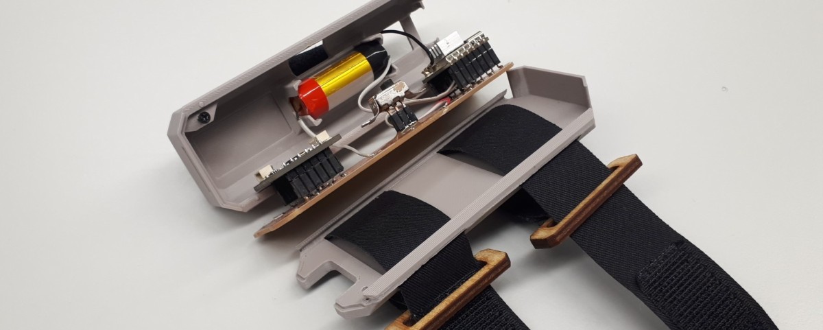
Remote


The PCB was integrated into the packaging by introducing radii at the bottom of the upper hull. The PCB was layed into the upper hull from below and was then held in place by mounting the bottom.


Wristband
To mount the PCB onto the forearm, two wristbands were fabricated. These were then threaded through the pockets in the bottom part of the housing.


Dongle
The dongle packaging is a simplified version of the remote packaging. The PCB is mounted in the same way. The bottom and the upper hull are connected using M2 wooden screws.


What I learned


Assembly
Putting the antenna inside the case led to messages not being transmitted. Therefore, it needed to be mounted at the outside. To make everything disassembleable, the antenna was mounted using velcro tape as well. For that, one part of the tape needed to be mounted on the housing’s surface. I used double-sided tape by tesa. All other tapes available at the lab were not sticky enough not to be accidentally torn off when removing the antenna.

The dongle was assembled by laying the PCB into the top of the housing and fastening the bottom and the top of the housing using four M2 screws. The remote was assembled by threading the wristbands into the bottom of the remote, laying the PCB and the battery into the top of the housing, sliding top and bottom together, and fastening them using one M2 screw.

Bonus: Surface finish
This section is included, because it is in general interesting for system integration, but it was not necessary for this project.
If it is not enough to just have a print, but to have a very smooth surface, there are different methods to achieve that. One is to use this product by Smooth-On. Another method is to use filler material (called Bondo or Spachtelmasse, in particular Feinspachtel). The procedure is as follows
- Put on safety equipment as described on the product. In my case this was ear, eye and respiratory protection as well as gloves.
- Add a little bit of hardener (included in the product) to the filler material and mix it well.
- Put a good amount onto the print so that every surface is covered. Do not put too much, as it would need to be grind away later.
- Let everything dry, roughly 24 hours.
- Grind everything to have a smooth surface wearing gloves to not put any residual fat or dirt onto the object (also wearing protection as above).
- first with roughness 120 (not too rough, otherwise this could add gaps to the surface).
- then with even finer roughness (like 500)
- Then, spray the part.
- Be careful! Have the nozzle 15 to 20 cm away from piece to not put too much coating in one place.
- Wait 15 minutes for one layer to dry.
- Add multiple layers while grinding between adding them. Again, be careful.
Use of Language Models
During writing this report, I did not use any language models.