Week 11: Networking & Communications
Table of Contents
This week was about various methods to connect multiple units using network protocols. In the group assignment, we connected our boards wireless using the ESP-NOW protocol. In the individual assignment, I made my board to be a simple USB-MIDI controller, sending note-on and control-change messages to a DAW on my laptop.
This Week’s Tasks
- Group assignment:
- Send a message between two projects.
- Document your work to the group work page and reflect on your individual page what you learned.
- Individual assignment:
- Design, build and connect wired or wireless node(s) with network or bus addresses and a local input and/or output devices
Digitial Files
- ESP-NOW
- USB-MIDI
- MIoTy Workshop
Connecting two Projects Using ESP-NOW
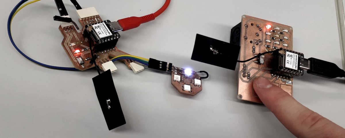
In the group assignment, Niclas and me worked together. The idea was to send each other input messages via ESP-NOW to react with our output devices accordingly. In this way, Niclas could e.g. control my lamps. We both were interested in wireless communication, so we opted for ESP-NOW. The group assignment page can be found here. I switched from using the Arduino IDE to using the ESP-IDF, a set of libraries for the ESP32 together with a set of scripts that allows for compiling and flashing c code onto an ESP32 board. For the serial monitor, I used the command line tool minicom.
What is ESP-NOW?
ESP-NOW is a communication protocol defined by Espressif. It operates on top of the data link layer, providing a simple communication method that does not require additional layers such as network or transport layers. Additionally, one only needs to specify a MAC address of the peer. No connection setup is necessary. This enables fast communication. Additionally, encryption is possible. ESP-NOW also supports sleep mode. For further reference, one can check the official website as well as the API documentation. A protocol analysis can be found here.
When compared to Bluetooth (BT), ESP-NOW has higher power consumption but significantly lower latency, following the paper Comparative Performance Study of ESP-NOW, Wi-Fi, Bluetooth Protocols based on Range, Transmission Speed, Latency, Energy Usage and Barrier Resistance by Dania Eridani et al.. Alternatively, one could experiment more with specific Bluetooth profiles for low latency and check if there are any differences. For this assignment, however, we decided to prefer ESP-NOW over bluetooth, because from the paper it is known to be well-suited for responsive applications and it is easy to set up.
The process of implementing ESP-NOW involves several steps. Initially, the device is initialized, and paired devices are added, e.g. via the MAC address of the peer. It is also possible to configure a node to broadcast. The function esp_now_send() is used for sending data, while esp_now_register_send_cb() registers a callback function to check if the sending was successful. For receiving data, esp_now_register_recv_cb() is implemented. It is important to avoid performing lengthy operations in the callback functions. Instead, the necessary data should be posted to a queue and handled by a lower-priority task. The transmission rate could also be configured.
Sending Messages
For an initial “hello world”, we used the official ESP-NOW example code from the ESP-IDF. There was nothing to set up but flashing two ESP32 boards having an antenna attached with the same code. Both found themselves via broadcast messages and sending data back and forth. The following is the main loop of the ESP-NOW example.
 1// in espnow_example_main.c
 2// ...
 3void app_main(void)
 4{
 5    // Initialize NVS
 6    esp_err_t ret = nvs_flash_init();
 7    if (ret == ESP_ERR_NVS_NO_FREE_PAGES || ret == ESP_ERR_NVS_NEW_VERSION_FOUND) {
 8        ESP_ERROR_CHECK( nvs_flash_erase() );
 9        ret = nvs_flash_init();
10    }
11    ESP_ERROR_CHECK( ret );
12
13    example_wifi_init();
14    example_espnow_init();
15}
16// ...
First, the non-volatile storage is initialized (which is required by the WiFi initialization). Afterwards, WiFi and ESP-NOW are initialized. During the ESP-NOW initialization, a periodic task is set up, send and receive callbacks are registered and a queue is created. Onto this queue, send and receive events are pushed. The set-up task then periodically takes the latest event and handles it, that is processing a packet to be sent or one that has been received. The example code worked without any problems.
Afterwards, we modified the example so that the MAC address of the corresponding peer is hard-coded. This would be how I would run it when using ESP-NOW for my final project.
For that, we needed to find out the mac addresses of our boards. I ran some arduino sketch to do that on each board. The addresses were as follows: Jakob: 64:e8:33:50:bc:70 Niclas: 64:e8:33:51:1d:14. In one node, the peer’s address could then be set using the function esp_now_add_peer. This function receives the structure esp_now_peer_info containing the peer’s MAC address as an input. The function esp_now_send is then used to send a message to a specified peer. At the peer, the receive callback needs to be defined to be able to process the received message. If one wants to send messages to another peer, one sets that up as well using the described procedure, but exchanging the MAC address accordingly. To then specify which node to address when sending a message, the corresponding address is to be given to the esp_now_send function as an argument. In our case, however, we only had two nodes, so one peer for each node.
After some unexciting debugging, we also got this working. Each node printed their output to the serial monitor.

The idea for now was that each of us sends their sensor data to the corresponding peer and everybody somehow makes their output devices react to that.
For the packet format, we used a union data type to be able to cast a general report type into either a ReportTouch or a ReportData. We did this to be able to have a common main.c file for both peers and just need to exchange one header (keyboard.h/gauntlet.h) to build the code for either of the projects.

The messages sent by Niclas had the following format:
 1// in espnow_example_main.h
 2// ...
 3typedef union {
 4  struct {
 5    uint8_t first; // Value of the first capacitive touch sensor.
 6    uint8_t second; // Value of the second ...
 7    uint8_t third; // Value of the third ...
 8  } Entries;
 9  uint8_t data[3];
10} ReportTouch;
11// ...
My messages followed the following format:
 1// in espnow_example_main.h
 2// ...
 3typedef union {
 4  struct {
 5    int8_t pitch; // Pitch of the gyroscope.
 6    int8_t roll; // Roll of the gyroscope.
 7  } Entries;
 8  uint8_t data[3];
 9} ReportGyro;
10// ...
Regarding the sending process, although queues are generally used to buffer outgoing and incoming messages, for this proof of concept, the decision was made to not implement this. Instead, just the current sensor value was read and sent within the send callback. Future improvements could involve adding sending and receiving queues and grouping multiple sensor reports into a single ESP-NOW message.
Every node enclosed their report in a general ReportData struct and sent it.
 1// in espnow_example_main.h
 2// ...
 3enum ReportType {
 4  REPORT_GYRO,
 5  REPORT_TOUCH,
 6};
 7
 8typedef union {
 9  struct {
10    uint8_t report[3];
11    enum ReportType type;
12  } Report;
13  uint8_t data[8];
14} ReportData;
15// ...
We had one problem with that: the data we received, first seemed nonsensical somehow. It seemed that we did not cast the generalit correctly. We did not debug this to the fullest extent, so we did not find out the exact reason. However, it was solved by changing the order of type and report in the ReportData struct.
To actually make the WS2812B LEDs react to the messages received, I took the blink example by ESP32 as a reference.
 1// in gauntlet.h
 2// This is the header file included for compiling the code for my project. When compiling the code for Niclas' project, the corresponding include statement was commented out and keyboard.h was included instead.
 3
 4// ...
 5// Both headers gauntlet.h and keyboard.h implemented process_report, as well as gather_report.
 6// This function processes the data received via ESP-NOW. It is invoked on a receive callback.
 7int process_report(ReportData rep) {
 8
 9  // ...
10
11  ReportTouch rep_to;
12  memcpy(rep_to.data, rep.Report.report, sizeof(ReportTouch));
13
14  ESP_LOGI(GAUNTLET_TAG, "Recieved: %d, %d, %d", rep_to.Entries.first,
15           rep_to.Entries.second, rep_to.Entries.third);
16
17  led_strip_set_pixel(led_strip, 0, rep_to.Entries.first, rep_to.Entries.first,
18                      rep_to.Entries.first);
19  led_strip_set_pixel(led_strip, 1, rep_to.Entries.second,
20                      rep_to.Entries.second, rep_to.Entries.second);
21  led_strip_set_pixel(led_strip, 2, rep_to.Entries.third, rep_to.Entries.third,
22                      rep_to.Entries.third);
23  led_strip_refresh(led_strip);
24
25  return 1;
26};
27// ...
Since the gyroscope was in use somewhere else at this time, I just wrote a mockup sending a ramp signal as the gyroscope output.
 1// in gauntlet.h
 2
 3// ...
 4// This function prepares/creates the data to be sent via ESP-NOW. It is invoked on a send callback.
 5ReportData gather_report() {
 6
 7  if (pitch < 127) {
 8    pitch++;
 9  } else {
10    pitch = -128;
11  }
12
13  ReportGyro rep_gy;
14  rep_gy.Entries.pitch = pitch;
15  rep_gy.Entries.roll = 0; // Roll stays always zero for now.
16
17  ReportData rep;
18  memcpy(rep.Report.report, rep_gy.data, sizeof(ReportGyro));
19  rep.Report.type = REPORT_GYRO;
20  return rep;
21};
Niclas used this to address his LED matrix, even if this is not visible in the video. A link to the full code can be found at the very bottom of this page.
Making a Simple MIDI Controller
Running the Example Code
I first tried out several variants of MIDI and USB-MIDI libraries for the Arduino environment. However, I noticed that they were not compatible with the ESP32S3. Eventually, I changed to use the ESP-IDF. I compiled and flashed the TinyUSB MIDI example. Plugging the ESP32 out and in again made it appear as a USB device on my laptop.

 1/**
 2 * @brief String descriptor
 3 */
 4static const char* s_str_desc[5] = {
 5    // array of pointer to string descriptors
 6    (char[]){0x09, 0x04},  // 0: is supported language is English (0x0409)
 7    "TinyUSB",             // 1: Manufacturer
 8    "TinyUSB Device",      // 2: Product
 9    "123456",              // 3: Serials, should use chip ID
10    "Example MIDI device", // 4: MIDI
11};
There were even more configuration possibilities. I would look into those later when things like power and timing would get important.
 1/**
 2 * @brief Configuration descriptor
 3 *
 4 * This is a simple configuration descriptor that defines 1 configuration and a MIDI interface
 5 */
 6static const uint8_t s_midi_cfg_desc[] = {
 7    // Configuration number, interface count, string index, total length, attribute, power in mA
 8    TUD_CONFIG_DESCRIPTOR(1, ITF_COUNT, 0, TUSB_DESCRIPTOR_TOTAL_LEN, 0, 100),
 9
10    // Interface number, string index, EP Out & EP In address, EP size
11    TUD_MIDI_DESCRIPTOR(ITF_NUM_MIDI, 4, EPNUM_MIDI, (0x80 | EPNUM_MIDI), 64),
12};
When connecting it to my DAW (Ardour), I could verify that it played some notes.
midi_task_read reads incoming data and does not tread them. Following the comments in the example code, this was necessary for prevent some communication issues.
Sending Note-On/Off Messages on Button Interaction
In the example code, note-on messages were sent by assembling a MIDI packet and passing that to the tud_midi_stream_write function.
1// in periodic_midi_write_example_cb
2// ...
3uint8_t note_on[3] = {NOTE_ON | channel, note_sequence[note_pos], 127};
4tud_midi_stream_write(cable_num, note_on, 3);
5// ...
My task was now to write a callback function sending a note-on message (in particular, a middle C) on a button-down event and another one for sending a note-off message for a button-up event. Both look similar, so just one of them is included here:
1static void button_down_cb(void *arg,void *usr_data)
2{
3    ESP_LOGI(TAG, "BUTTON_DOWN");
4    if (tud_midi_mounted()) {
5        uint8_t note_on[3] = {NOTE_ON | CHANNEL, 60, 127}; // Sending middle C (pitch = 60) with max velocity (127).
6        tud_midi_stream_write(CABLE_NUM, note_on, 3);
7    }
8}
Next, I needed to somehow handle the button events. This I did by using the iot_button library. Somehow, I did not get to run it by following its documentation, so I checked the corresponding header files and the unit tests in the git repository to see how a button is to be set up in the GPIO. To install this dependency, I used the component manager. This basically downloads the necessary .c and .h files and adjusts some config files in the repository accordingly.
I first tested the button pressing with the serial output. Following that, the button events got registered.

Sending Control Change Messages
Not only did I want to incorporate something that resembles a button-like behavior, but also something that changes its value continuously, similar to a knob. This was necessary in order to include the gyroscope. In MIDI, the position of such knob-like things are encoded in control change messages. However, I did not know how the MIDI standard defined such messages, so I looked up the MIDI standard. There are two versions of it. Based on the example code I have seen so far, I assumed, the library I used implemented MIDI 1.0. However, the structure of the MIDI messages (for both 1.0 and 2.0) was reported in the MIDI 2.0 standard in a much more readable way. Also, while the MIDI 2.0 standard is written down in more or less one large document, the MIDI 1.0 standard includes the core specification and many several addenda.


For changing the code, the most important information was that index in the code corresponded to control number in the MIDI specification and data to value. I chose the control number to be 16, which is reserved for generic knobs (i.e. it is not specified if it is a volume knob, a filter knob etc., I wanted to leave this option to the user).
The gyroscope values, I mocked since the sensor were in use by someone else at the time of programming. The callback one can see below was periodically executed by a timer.
 1static void mock_gyro_cb(void *arg) {
 2    static uint8_t cc_value = 0;
 3
 4    if (tud_midi_mounted()) {
 5        ESP_LOGI(TAG, "Writing MIDI data %d", cc_value);
 6        // Create MIDI packet.
 7        uint8_t index = 16; // Also known as "control number". CC 16 indicates a "generic control".
 8        uint8_t data = cc_value; // Also known as "control value". The "position" of the "knob". Will be pitch/roll.
 9        uint8_t cc_msg[3] = {CONTROL_CHANGE | CHANNEL, index, data};
10        tud_midi_stream_write(CABLE_NUM, cc_msg, 3);
11    }
12
13    // Generate a periodic ramp signal from 0 to 127.
14    if (cc_value < 127){
15        cc_value++;
16    } else {
17        cc_value = 0;
18    }
19}
It worked. Messages were received by my DAW!

TS-UNB Workshop
Additionally, we had a workshop on the standard Telegram Splitting Ultra Narrow Band (TS-UNB) with MIoTy as its commercial name. I learned a bit about impedance matching in case antennas are used. We designed a receiver module containing an ISM transmitter chip as well as a RPi Pico which would run the code specific to the standard.


Reflections
What Helped Me Moving Forward
For the group assignment, I worked together with Niclas. We did pair programming, so one person is typing, but two people are looking at the code while it is programmed. There were quite some moments where coding mistakes were discovered on an early stage thanks to that procedure. Also, it was very fun to work together :).
What I Learned
I learned how to implement a functioning MIDI controller which involved assembling MIDI packets so that they follow the MIDI specification. I learned how to use the ESP-NOW protocol for wireless and low-latency communication. The MIoTy workshop provided a short excourse to working with antennas and impedance matching.
What Went Wrong
Luckily, everything went smooth.
What Went Well
The programming went well. I did not expect that, since debugging with C usually is way more tedious. It definitely helped that it was possible to start with example code from the ESP-IDF. There was some documentation missing, but it was possible to find out the way of using it looking at unit tests and header files.
Use of Language Models
During writing this report, I used the following prompts asking ChatGPT 4o mini to form bullet points to prose text.
1Take the following bullet points and form grammatical and orthographically correct new bullet points out of them. Do not add any additional information. Only use those words and letters used in the original bullet points and, additionally, those that are absolutely necessary to build grammatical and orthographically correct new bullet points out of the original bullet points. Formulate everything in past tense. Correct spelling mistakes:
2
3<insert bullet points>