Week 10: Output Devices
Table of Contents
This week, we were introduced to different output devices (such as various types of motors, addressable LEDs, etc.), and how to work with them. In my personal assignment, I designed and built small addressable LED matrix based on WS2812B LEDs and set it up to be controlled by the gyroscope I worked with in the input-devices week.
This Week’s Tasks
- Group assignment:
- Measure the power consumption of an output device.
- Document your work on the group work page and reflect on your individual page what you learned.
- Individual assignment:
- Add an output device to a microcontroller board you’ve designed and program it to do something.
Measuring Power
For the power measurement task, I planned to first make the output device and then measuring its power. Therefore, I put this part to the end of the documentation. You can find the corresponding section here. The group assignment page can be accessed via this link.
Making Output Devices
At this point, I already had a clear idea of what the final project would be: a glove having different inputs (at minimum a gyroscope and some type of pressure sensor for the finger tips) to send out MIDI signals via USB,_e.g._to control synthesizer patches in a digital audio workstation (or anything else you can use MIDI controllers for).

Vibration Motor
I ordered a bunch of (eccetric rotating mass) ERM vibration motors on roboter-bausatz.de. One can find these by searching for “smartphone vibration motor”. I could not find out from the data sheet if they are brushed or brushless. However, what is important for driving the delivered packages is just to provide a voltage. The “driver” would thus be as simple as having an N-MOSFET (one rule of thumb that was suggested to follow was to use N-MOSFETs for everything except some corner cases) to switch on and off the power supply for the motor. The circuit would look as follows.

The MOSFET is to be connected so that D is connected to the GND of the power supply. Note that if a high voltage is connected to the gate (i.e. the MOSFET is conducting) it is still only conducting in one direction (same as with a diode).
Another aspect to think of is that once the MOSFET is switched to be non-conducting, there is no current flowing provided by the battery anymore, but the motor might continue turning a while. This could induce a current in the other direction. When the motor is large enough, this current could be so large that it would lead to a breakthrough of the MOSFET. Therefore, it is advised to have a diode in parallel to the MOSFET where the induced current could flow through to protect the MOSFET. Note that the diode is not conducting if the MOSFET is switched on and the current is provided by the battery.
At this point, this seemed to be rather straight-forward, but I did not have a clear idea about how to integrate the LEDs, so I decided to focus on those for this week.
Making the Pixel Matrix Using WS2821B LEDs
The PCB I had in mind consisted of multiple components: boards for the fingers to attach only the LEDs on (plus additional components needed) and a “main PCB” for mounting microcontroller, the gyroscope etc. and to connect both using ribbon cables. I designed this week’s PCBs with that final idea in mind. During the design, I referred to the data sheet and to the guide by Adafruit. There was one thing I did not do correct: the level of the signal to communicate with the LEDs was of 3.3V. This turned out to work well. However, if one wants to do it by the book, one would need to use a level shifter to have the signal of 5V.
Creating a new Footprint
For mounting the ribbon cable I created a new footprint. In the following images, one can see how this was done. Later, I got a recommendation to use the ribbon cables from the FAB inventory and the corresponding connectors as well as their footprints in the KiCad library.


Designing the Main PCB
According to the Adafruit guide, there needs to be a resistor between 300 and 500 Ohms in front of the data input of the first LED.
From the Adafruit documentation as well as from the WS2812B documentation, I found that there are capacitors to be placed between GND and VDD. Their purpose is to smooth gaps in the power signal. In case of such a gap, the capacitor (which would be charged by then) would discharge and act as a voltage source temporarily. Smaller capacitors (around 0.1uF) are to be placed in front of each LED (as closely as possible). In case of a very power-hungry output device (such as a very long LED strip), another, larger capacitor (100uF) is to be placed in parallel to the voltage source. A discussion on that topic can be found on the corresponding Wikipedia page.


I then noticed that having a separate trace for GND is a bit annoying and decided to try out having a GND plane. The workflow to do that is documented in the following pictures.


Designing the Finger Part
I then designed the PCB to attach to a finger.


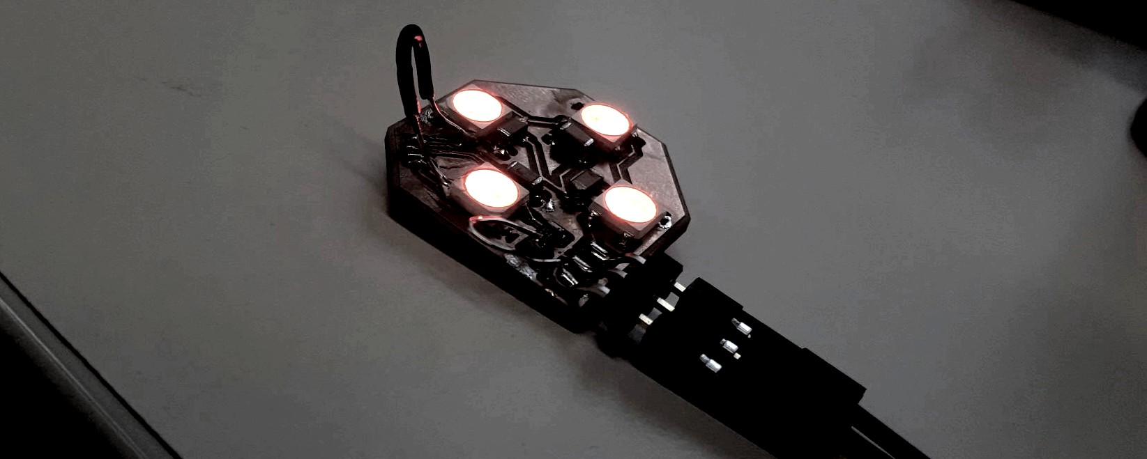
Assembling
I then assembled everything.


Programming the Pixel Matrix
Testing
For testing, I programmed the ESP32-S3 with the example code from Adafruit using the Arduino IDE.


Integration With the Gyroscope
I then created a new Arduino sketch to combine the LEDs with the input from the gyroscope. Alternatively, the ESP-IDF could be used following this example. I wanted that LED to light up towards which the gyroscope was tilted.


 1// before setup()
 2float rad_to_brightness(float x) {
 3  // x is in [-PI, +PI]
 4  int heaviside = x >= 0;
 5  return heaviside * (sin(2*x)/2 + 1);
 6}
 7
 8// ...
 9
10// loop()
11    // ...
12    // retrieving pitch, roll into struct `ypr`
13    // ...
14    // Make each LED lid up when the gyro is tilted in the corresponding direction.
15    pixels.clear();
16
17    // ..North/South (pitch)
18    pixels.setPixelColor(LED_NORTH, pixels.Color(0, rad_to_brightness(ypr.pitch)*255, 0));
19    pixels.setPixelColor(LED_SOUTH, pixels.Color(0, rad_to_brightness(-ypr.pitch)*255, 0));
20
21    // ..Eats/West (roll)
22    pixels.setPixelColor(LED_EAST, pixels.Color(0, 0, rad_to_brightness(ypr.roll)*255));
23    pixels.setPixelColor(LED_WEST, pixels.Color(0, 0, rad_to_brightness(-ypr.roll)*255));
24
25    pixels.show();
26// ...
The sketch, I assembled from the gyroscope example I used in the input devices week and from the NeoPixel example. Note, that the output values of the sensor were reported in radiants.


Measuring the LED Matrix’ Maximum Power Consumption
For measuring the power, the Rigol multimeter was connected for current measurement and the multimeter was measuring voltage. The ESP32 was programmed to run all LEDs on full brightness.


Reflections
What I Learned
- How to create copper planes in KiCad.
- How to integrate WS2812B LEDs into a circuit.
- How to integrate simple DC motors into a circuit.
- The wider pads/traces are designed the more stable the soldered connection will be.
What Went Wrong
- Soldering the finger PCB did not work as expected.
What Went Well
- Integrating gyroscope and LED matrix.
What I Would Do Differently
- I would use the ribbon cable connector footprint for the PCB design to connect finger and hand PCB.
Digitial Files
Use of Language Models
For writing this report, I did not use any language model.