Week 3: Computer-Controlled Cutting
Table of Contents
This week, we got introduced to vinyl and laser cutting including machine setup and the corresponding safety training. I designed and lasered a cardboard construction kit to assemble plant-like constructions with. As an introduction to vinyl cutting, a custom sticker was designed and fabricated.
This Week’s Tasks
- Group assignment:
- Do your lab’s safety training.
- Characterize your laser cutter’s focus, power, speed, rate, kerf, joint clearance and types.
- Document your work to the group work page and reflect on your individual page what you learned.
- Individual assignments
- Design, laser cut, and document a parametric construction kit, accounting for the laser cutter kerf, which can be assembled in multiple ways.
- Cut something on the vinyl cutter.
Safety Training & Laser Cutter Operation
The group assignments everyone documented on their personal websites first. Afterwards, the content was transferred to the group page.
The lab safety training consisted of reading the rules and answering questions about it in a quiz.


Before operating the laser cutter, Ferdi gave an introduction on thursday morning. It covered types of lasers, proper cleaning, and safety (do not cut PVC, wear glasses when operating the laser, keep the lid shut, have something to extinguish a flame), such as avoiding certain materials like PVC. He explained the differences between DC, AC, diode, and fiber lasers, as well as laser bed types.
Afterwards, we went into part of the lab where the laser was. Benedikt and I made pictures to explain the operation procedure.
Before operating the laser cutter, the following steps must be completed (images and notes are taken by both Benedikt and me simultaneously):


Characterizing the Laser Cutter
The group assignments everyone documented on their personal websites first. Afterwards, the content was transferred to the group page.
Focal Distance
As the focal length we describe the distance between the bottom end of the laser carriage and the focus point of the laser beam. The laser is to be adjusted so that the surface that is to be cut is just at the same height of the focus point. Therefore, finding out the focal distance is important when operating the laser. To do that, a foam block was cut with the head adjusted to almost touch the foam block from above.


Power & Speed
The laser cutter was rated for a maximum output of 80 W at full power. Since our laser tube was considerably old, the real maximum power probably was lower than that. Power could be adjusted in percents of the original maximum power output.
To determine good values for the use with cardboard, we conducted a grid search over the power and speed. The top diagram shows cutting results, and the bottom one shows engraving results.


Additionally, we discovered that it is possible to set the jump interval, i.e. the distance between the lines of the laser when engraving. A default value is 0.2mm. A smaller value leads to a higher engraving resolution but leads to more time needed for the same engraving.
Frequency

Kerf
To measure the kerf, wanted to cut 10 rectangles lying next to each other and measuring their width altogether after cutting.

We chose a power level of 90% and experimentally determined the speed through a grid search, starting with increments of 5mm/s between 5mm/s and 35mm/s, then fine-tuning between 15mm/s and 30mm/s in 1mm/s increments. We found that 18mm/s fully cut the material. Next, we cut the rectangles and measured them as described.

To calculate the kerf, we subtracted the measured total width from the original width and divided the difference by the number of parts which gave a kerf of (10 * 10mm - 99mm) / 10 = 0.1mm.
Other
As a software for operating the Laser, RDWorks was used.
Parametric Construction Kit
Joint Clearance Test
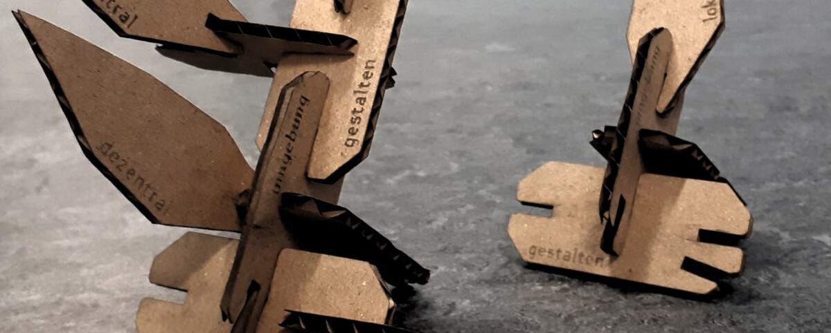
The construction kit that was named in the the assignment was a set of cardboard pieces that can be assembled together making use of pre-cut slots (joints). An example can be seen in the title picture of this page.

In order to fabricate the kit, however, one needed to decide for a slot width. There were two reasons why the cardboard thickness could not simply be chosen: the kerf of the laser cutting away material (making the slot wider than planned) and the cardboard being compressed when fitted together. For this, a comb was to be designed. This comb was thought to have multiple slots, each assigned a different width. It could then be used for checking which slot width would be the best. The slot widths that were to be covered were 2.5, 2.6, 2.7, 2.8, 2.9, 3.0, 3.1, 3.2, and 3.3 in the first trial. From now on, the widths of the slots were noted as assigned in the design software, not as they were in reality. The real width differed from the given width since the kerf cut away some material. The design was made using FreeCAD.
The following series of images shows the process of designing and cutting the comb.


mid_width was the width of the fourth slot when counted from the right.


.dxf file in RDWorks.


mid_width param in the created spreadsheet and is such a way that the highest slot width was 2,6mm.


.dxf/.svg file.
During the comb’s design, I learned some things regarding parametric design. I first became confused with the constraints, often over-constraining parts and not knowing where to apply the constraints. From this, I learned that it is a nice way to first apply only those constraints you think are absolutely necessary to fulfill your idea, check what parts are still to be moved and think about further constraints then. I also realized that it’s helpful to make sketches in a modular manner rather than trying to do everything in a single sketch. You could make a sketch, pad it, and then create a new sketch on top of that. Ferdi suggested that if I have the choice to do something in one or two sketches, I should consider choosing to do it in two.
Design the Construction Kit
I wanted to make a plant construction kit, inspired by nature. I aimed for natural-looking elements so that building the plant resemble human interaction with nature, making it touchable. I wanted the design to be asymmetric, reflecting the irregularity found in nature. It should be thin but consist of many parts. I first thought about which shapes to design, considering elements like the base plate, some circular connectors, a stem, and leaves. I decided against adding blossoms as it would be too complicated.


At this point, I switched to CAD. With the following sequence of images you can follow the design process of the kit.


Cutting
During the cutting process, I encountered some issues with the .dxf file, particularly with font selection and the cutter’s settings. After troubleshooting the font problem and adjusting power settings, I successfully cut the pieces. I also resolved issues with the cutter going over outlines twice by ungrouping elements in Inkscape before exporting. In the end, I refined the design, making it ready for assembly and sharing with others.


.dxf and importing them in RDWorks. At the end, I chose Arsle Gothic.


connect selected nodes function. After doing this, everything looked good.


Using the Vinyl Cutter
To design the sticker, I created the text in Inkscape, chose a nice font, and converted it to a path. I also realized that the letters were each cut separately, which made it difficult to handle them. To fix this, I created a background shape and subtracted the letters from it before saving the file again as DXF and cutting it.


Reflections
What Was New
- Laser and vinyl cutting. It is great. I entered a world of joy. I am especially amazed by the fact that there now is a finished design for something that can be fabricated again and again and again and again and again and …
What Went Wrong
- Group assignment scheduling a bit chaotic from our side, but we managed and learned from it.
- CAD parametric design. It did not go wrong, I just took my time to learn it and I learned quite some things:
- Do not draw open 2d shapes, always close them.
- How to properly constrain a drawing so that you dont overconstrain it later: add those constraints you think are absolutely necessary for your drawing. then move around the parts that are still moveable and add carefully reiterate this point until your drawing is fully constrained.
What Went Well
- Before pushing, I checked by website and used image compression for images larger then 140kb. QDirStat was very helpful for viewing which files were how large.
- Using CAD itself was pretty straight forward.
- I finished most things (except the documentation) by Sunday.
- I feel like I am getting better and better when it comes to documentation (taking screenshots during working, taking notes on the go etc.). I get a feeling when to document what and where on my website so it fulfills the requirements and is easily accessable. My way of documentation is basically to collect as many information as possible in a structured way, where the structure itself enables rapid access (via bookmarks in file browser, aliasses for navigating the CLI etc.) and at the same time does not introduce a threshold for documentation.
What I Would Do Differently
- Schedule group assignments together with the group right after Neil’s lecture.
- When making a parametric design: assign dimensions so that it would be easier to handle, e.g. when you are manufacturing it manually.
Digitial Files
- Pressfit kit (
outline.svgandtext.svgsuffice for just lasering it) - Clearance test comb
- Vinyl sticker
Use of Language Models
During writing this report, I used the following prompts asking ChatGPT 4o mini to
- form bullet points to prose text:
1Take the following bullet points and form prose text out of them. Do not add any additional information. Only use those words used in the bullet points and, additionally, those that are absolutely necessary to build grammatical sentences out of the bullet points. Formulate everything in past tense. Correct spelling mistakes: 2 3<insert bullet points> - summarize longer texts:
1Summarize the following text in one paragraph:
2
3<insert text>