Week 2: Computer-Aided Design
Table of Contents
This week was about getting familiar with 2D and especially 3D design software. I refreshed my CAD skills using FreeCAD and introduced myself to Blender.
This Week’s Tasks
- Evaluate and select 2D and 3D software
- Demonstrate and describe processes used in modeling with 2D and 3D softwares
- Demonstrate image and video compression
This week, the major outcome was getting familiar with 3D and 2D modeling software. The idea was to look at as many tools as possible at first, model something simple, and then focus on the tools one really wanted to go in depth with. To get an idea about this weeks scope, I looked at the example assignment for the week. Then, I listed the software I was interested in investigating:
- 2D design:
- LibreCAD: creating parametric 2D designs.
- Inkscape: creating and manipulating vector graphics.
- GIMP: Image manipulation.
- 3D design:
- FreeCAD: 3D parametric design.
- Blender: Rendering a model created in CAD or creating meshes in a more freeform way.
- Onshape: Collaborative design, might be nice if I want to do a final project with someone together.
- XDesign: To see how a proper, professional, commercial CAD software looks and what features there are.
- Antimony: Modeling software using functional representation and whose node-based interface allows you to do unconventional, crazy things. I figured it might be nice for organic shapes!
- Other interesting Software, I did not investigated further:
- OpenSCAD: Parametric 3D design using a scripting interface
- SolidWorks, SolveSpace: More professional CAD tools.

2D Modeling
Before going on with the 3D design, I looked a bit into available 2D design software. GIMP is a tool for manipulating images. It is the open-source twin of Photoshop. With GIMP, I have some experience, I usually do posters and covers for DJ mixes:


LibreCAD, is nice to create parametric 2D designs. I asked my instructor Ferdi and one of my peers who looked into it in more depth about their opinions on it. They said it is nice for 2D design, but you can also use FreeCAD for doing all the things that are possible in LibreCAD. LibreCAD might get useful when you get a digital technical drawing from somewhere else and you want to modify it. As this is supposed rather seldomly, I did not go in depth with this software.
3D Modeling
Ferdi, our instructor, mentioned that you want a CAD software that is “feature”-based, meaning that everything you do – whether rounding an edge or extruding – gets saved separately from the object, allowing you to change it later. Blender, for example, is not entirely feature-based. The software should also use constructive solid geometry (CSG). CSG creates complex 3D shapes by combining basic, predefined solids using operations like union, intersection, and difference. Additionally, it should be parametric, meaning you can change parameters later on and associative, allowing you to add constraints.
He also talked a bit about what other software exists in the CAD world. They include CATIA, Siemens NX, and Creo. Many of the bigger commercial CAD tools have smaller counterparts: SolidWorks is the smaller version of CATIA, SolidEdge is the smaller version of Creo, and Inventor is the smaller version of Fusion360.
Commercial CAD Software
I still wanted to investigate, what distinguishes free CAD software from commercial ones, so I again talked with Ferdi about it. He gave an example: in FreeCAD, a rounding had a constant radius. In CATIA, however, you could specify two different radii on two opposing edges. CATIA then calculated the radius of rounding along the edge to be interpolated between these two radii. In FreeCAD, this was not possible. That being said, there were more convenient options available in commercial CAD software that were not included in FreeCAD. This reaches from rather simple things, such as a variable rounding to more complex ones, where in FreeCAD you “enter a world of pain”, as Ferdi said. However, these were problems you encountered when you needed very specific things in very specific fields. So for many CAD tasks, FreeCAD was sufficient.
FreeCAD
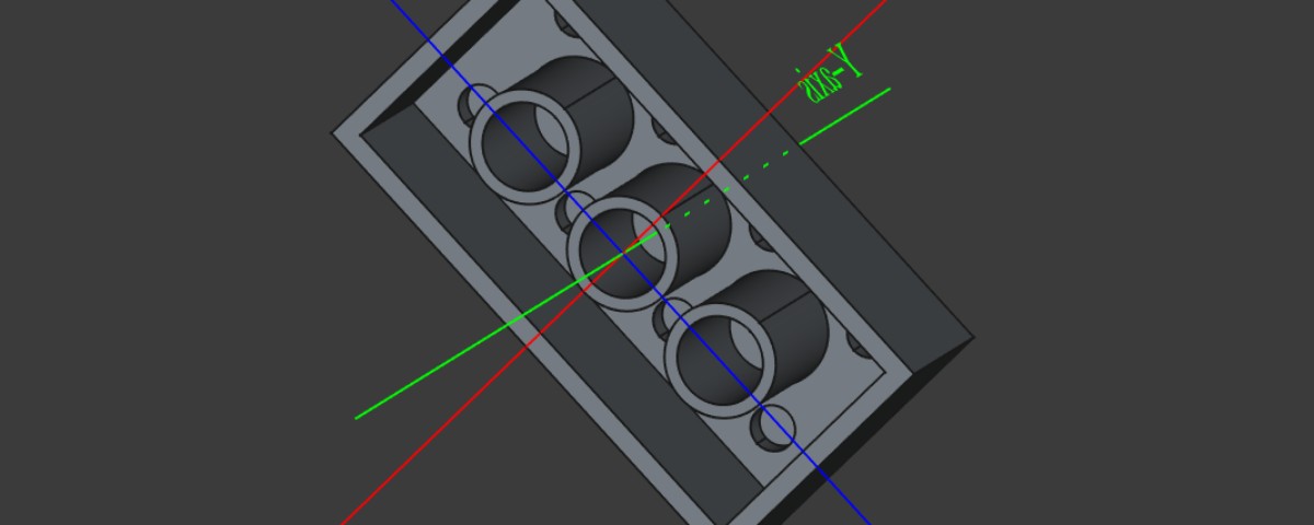
So I went on to FreeCAD. The following pictures show a process of modelling a construction toy brick. It was part of a workshop from Ferdi.
We learned to apply constraints (horizontal, vertical, and symmetry etc.) with shortcuts available for efficiency. We got to know about fully constraining sketches, padding (or as other CAD tools call it “extruding”) them into 3D objects. We used linear patterns and multitransform to duplicate padded components. Additionally, the workshop covered the importance of proper technical drawings, including the use of title blocks (or Schriftfeld as it is called in German) and the need for general tolerances (DIN ISO 2768) to ensure accurate manufacturing.


Furthermore, we got to know about other features of FreeCAD:
At the end of the FreeCAD workshop, we explored several additional features. We learned about the CAM module, which is used for CNC machine programming. In the reverse engineering workspace you can create a surface from a point cloud, though FreeCAD might not be able to perform this task effectively. For this, programs like CATIA and Geomagic DesignX were suggested, with Geomagic DesignX costing 1,750 euros for the basic version. The robotics allows you to program robot arms giving them a trajectory to follow. There, Ferdi talked a bit about inverse kinematics, where, instead of individually controlling joints, you could move the hand and let the software calculate the required movements of the arm, forearm, and wrist. FreeCAD was also noted for its capability as a Building Information Modeling (BIM) tool, which allows for designing houses and includes a parts catalog for construction. The most widely used BIM software at that time was Revit.
Blender & Final Project
For blender, we received a workshop by Ferdi as well. My notes can be found here. Also, I really liked how Nadieh used blender for rendering pieces she designed earlier in a CAD software.
During Ferdi’s workshop, we covered the basics of navigation and shortcuts, including zooming, orbiting, and panning, as well as how to manage and customize window layouts. We learned how to add and manipulate objects using scaling, rotating, and extruding, and how to apply modifiers such as subdivision surface for smoother surfaces. The below images show a figure that was modeled using simple meshes (cubes in this case) and applying a subdivision surface modifier on it afterwards.


For my final project, I want to build a synthesizer that has some organic shape resembling the sound it makes. Following the introduced procedure, I modeled an abstract organic shape resembling a flower with a bulbous body: a first Idea of how the synthesizer could look. The audio jack could fit into the blossom of the flower and all parts can be cased in the voluminous body.

Compression
For compression, I chose one image (134.7kB) and one video (76MB) from my library.

1magick jail.png -resize 1000\> -quality 90 -format jpg jail.jpg1000\> for the -resize option indicates that the image is only to be resized if its width is higher than 1000 pixels. This led to the following image, which still looked considerably good while having a size of 21.9kB.


For video compression, I took this page as a reference. I augmented the command to also cut the video in time.
1ffmpeg -i weird_rotary.mp4 -vcodec libx264 -b:v 1000k -vf scale=-2:1080 -ss 00:00:16 -to 00:00:18 -an weird_rotary_compressed.mp4Furthermore, I read into the documentation of imagemagick. Also, I tweaked my screenshot workflow a bit to use scrot instead of spectacle. I also wanted to include compression right after taking the screenshot using the bash pipeline syntax and imagemagick. Afterwards, the image should be copied to the clipboard to paste it directly somewhere as a compressed .jpg. However, I found that it is not possible to copy jpeg to the clipboard using xclip :/, so I continue just saving screenshots to a separate folder I have fast access to.
Reflections
What Was New
- Navigating in blender and using the subdivision surface modifier to get some interesting shapes.
- Using FreeCAD.
What Went Wrong
Nothing really went wrong. It just was a bit unfortunate that I had to finish some non-Fab-Academy things for my studies and therefore did not have the time to look as deep into 3D modeling as I wanted, but I am confident that I will be through this soon.
What Went Well
Documentation was really efficient this time. I ended up doing screenshots using scrot with a press of a button. Then, I crop all pictures using shotwell. I am amazed how efficient this was.
What I Would Do Differently
Next time, I would focus on finishing and documenting the Fab Academy assignment as early as possible to focus on the study assignments I have to do. This time, I did part of the Fab Academy assignment and “just had to write that down”, but this is still a considerable amount of work.
Digitial Files
- Inkscape
- FreeCAD
- Blender
Use of Language Models
During writing this report, I used the following prompts asking ChatGPT 4o mini to
- form bullet points to prose text:
1Take the following bullet points and form prose text out of them. Do not add any additional information. Only use those words used in the bullet points and, additionally, those that are absolutely necessary to build grammatical sentences out of the bullet points. Formulate everything in past tense. Correct spelling mistakes: 2 3<insert bullet points> - refine bullet points:
1Take the following bullet points and form grammatical and orthographically correct new bullet points out of them. Do not add any additional information. Only use those words and letters used in the original bullet points and, additionally, those that are absolutely necessary to build grammatical and orthographically correct new bullet points out of the original bullet points. Formulate everything in past tense. Correct spelling mistakes:
2
3<insert bullet points>