08 Electronics Production
Group Assignment
The weekly group assignment can be accessed here.
To test the capabilities of our Carvera, we used Neil’s test. For milling, we used a 0.2 mm V-bit for the traces and a 0.8 mm end mill for the outlines.

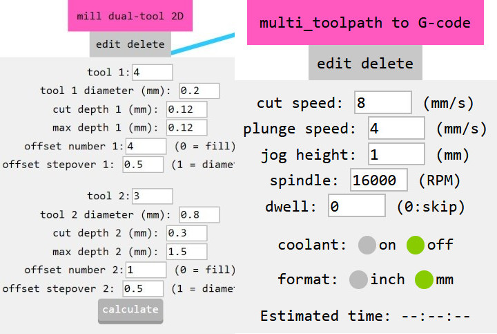
Since mods provides two preconfigured programs for the machine, we used the default cutting parameters. The only adjustments we made were to the tool diameters, offset number, cut depth, and max cut depth to accommodate the use of FR-4 with HSS end mills:
| Parameter | Value |
|---|---|
| Tool 1 | 4 |
| Tool 1 diameter (mm) | 0,2 |
| Cut depth 1 (mm) | 0,12 |
| Max depth 1 (mm) | 0,12 |
| Offset number 1 | 4 |
| Offset stepover 1 | 0,5 |
| Tool 2 | 3 |
| Tool 2 diameter (mm) | 0,8 |
| Cut depth 2 (mm) | 0,3 |
| Max depth 2 (mm) | 1,5 |
| Offset number 2 | 1 |
| Offset stepover 2 | 0,5 |
| Cut speed | 8 mm/min |
| Plunge speed | 4 mm/min |
| Spindle | 16.000 rpm |
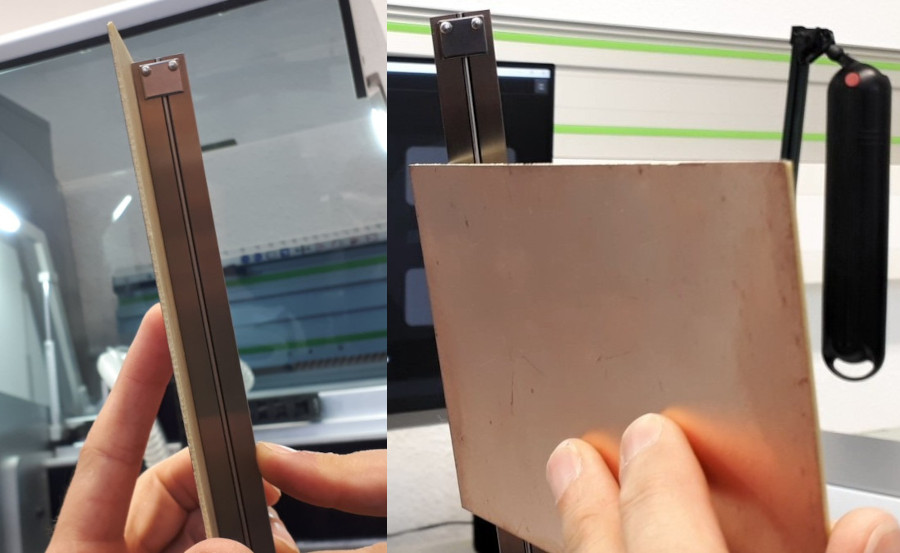
To achieve optimal results and minimize the risk of breaking mill bits, we ensured that our PCB stock material was perfectly flat. Normally, this is done using a straight edge, but since we didn’t have one readily available, we used a caliper gauge. Holding it against the back of the material while looking towards a light source allowed us to check for gaps. If gaps were present, we carefully bent the stock material until it was as flat as possible.
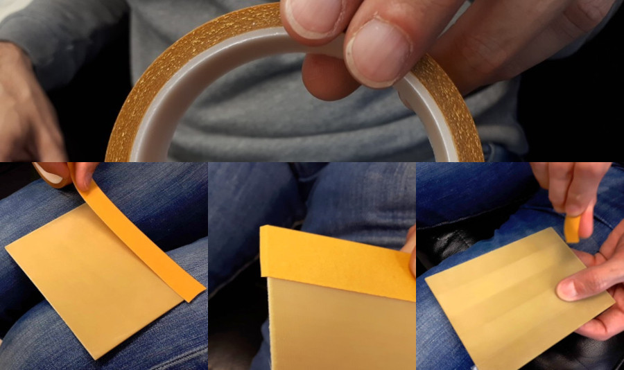
To secure the stock material on the machine bed, we used thin, non-reinforced double-sided tape. In general, the cheapest double-sided tape works best—reinforced tapes should be avoided as they can create uneven surfaces. For proper adhesion while still allowing easy removal, we applied three strips of tape across the entire width.
A flat machine bed is crucial for achieving accurate results. To ensure this, Ferdi milled the entire bed flat. To reduce machining time, he used a 6 mm flat end mill with the 6 mm collet for the Carvera.

To change the collet, he used the official tool provided by Makera. If an end mill is too large for the tool changer, it can be manually changed using the following commands:
M490.1 // Tightens the spindle collet to secure a new tool
M490.1 // Loosens the spindle collet and releases the current milling bit
A full list of supported G-code commands is available on Makera’s website.
Setting the Z = 0 Position
There are three ways to correctly set the Z = 0 position:
1. Using the machine’s wireless probe
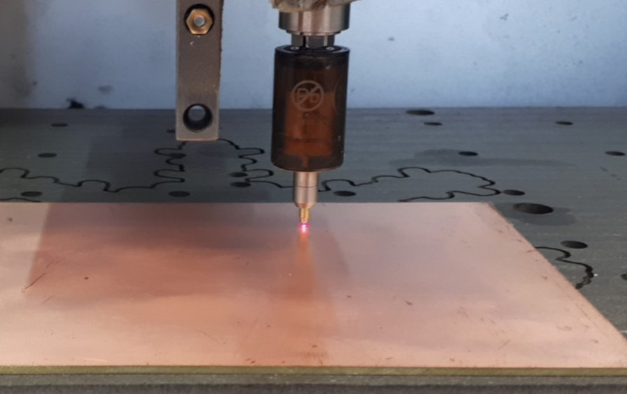
2. Using a multimeter in continuity test mode (or a dedicated continuity tester) by placing probes between the copper layer and the V-bit, then slowly lowering the Z-axis in small steps
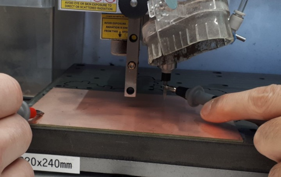
3. Listening for the V-bit scratching the copper layer—this should also be done slowly and in small steps
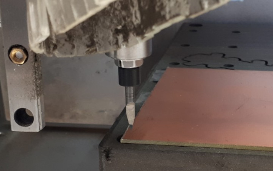
The final result looks like this:

Analysis and Design Adjustments
Since we are using FR4 with HSS end mills, we cleaned the board using a razor blade and steel wool before comparing it to the original design file.
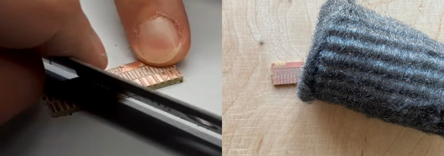
Neil’s test ranges from 0.001" (0.0254 mm) to 0.02" (0.508 mm). For clarity, I will use millimeters for all further comparison.
The thinnest track that produced good results was 0.254 mm.
The smallest clearance that looked acceptable was also 0,1778 mm.
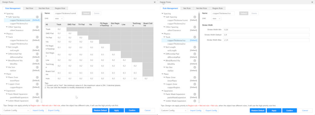
For my design, I will use the following parameters:
Clearance: 0.2 mm, except
* 0.3 mm clearance to the board outline
* 0.3 mm clearance between tracks and large copper areas
Trace width: 0.26 mm – 2.54 mm, with a typical width of 0.4 mm, ensuring all routing can be done without manual adjustments.
