03 Computer-Controlled Cutting
How to Use the Laser Cutter?
Our group assignment initially faced some challenges due to suboptimal communication, but ultimately, it progressed smoothly and successfully. Before operating the laser cutter, the following steps must be completed:
- Put on laser safety goggles from the storage cabinet.
- Open the top window and install the ventilation cover by inserting it into the window frame.

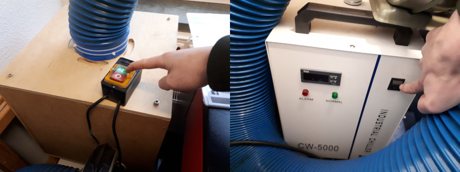
- After installing the ventilation system, press the top button to activate the exhaust.
- Press the button on the chiller to activate the cooling system for the laser cutter. If the chiller is not activated, the laser cutter will display an error message.
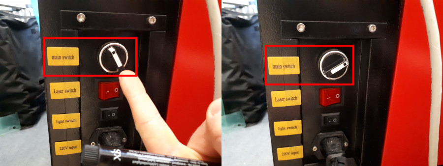
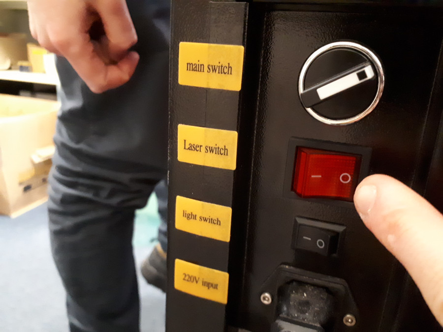
- Flip the main switch to power on the laser cutter (the laser tube remains deactivated at this stage)..
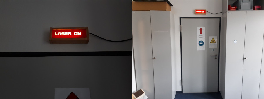
- Outside the room, above the door, the laser warning sign will light up, indicating that anyone entering must wear laser safety goggles and that the door should remain closed. Unnecessary movement in and out of the room should be avoided.
- Next, place the material inside the laser cutter by opening the large top lid.
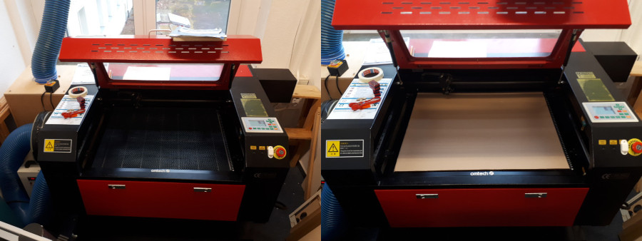
- The focus has a significant impact on cutting results, so it is crucial to set the height correctly using the two buttons on the right side of the laser cutter.
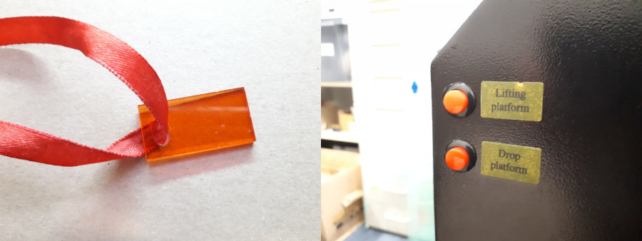
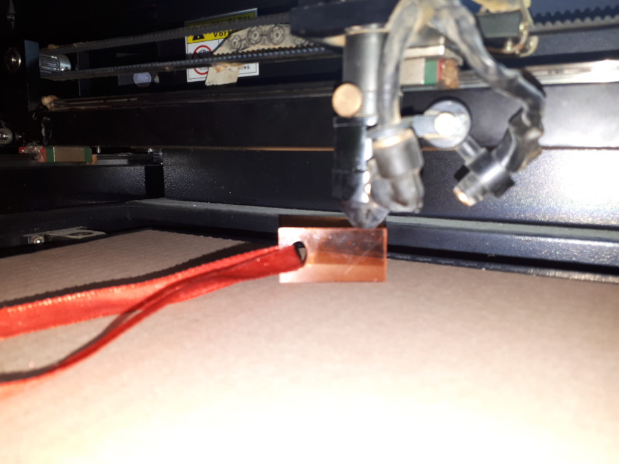
- The focus point is correctly set when the focus gauge can barely move freely between the material and the laser carriage when placed on its long side.
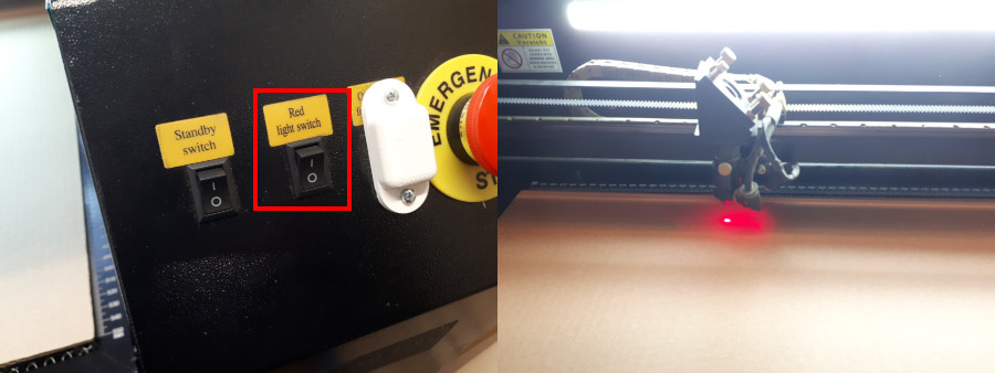
- To make positioning and preparation easier, a small light can be activated to indicate the laser's position once the focus is set correctly. To enable this, flip the second lever on the top right of the laser cutter.
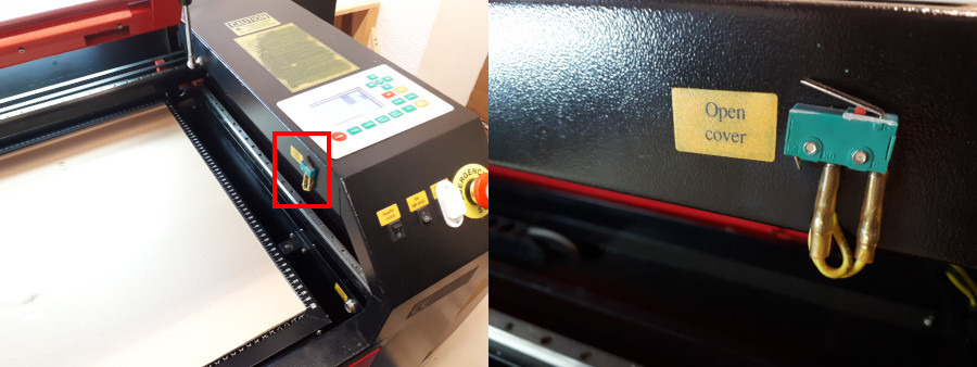
- The laser cutter will not operate if the top lid is open. This is ensured by a micro switch that detects the lid’s state (open/closed).
- The laser cutter is controlled via the panel located on the top right side:
| Number | Button | Function |
|---|---|---|
| 1 | Origin | Sets the work origin at the current laser carriage position (X and Y only). |
| 2 | Frame | Outlines the work area of the laser job with a rectangular frame. |
| 3 | Pulse | Activates the laser briefly when the laser tube is enabled. |
| 4 | Speed | djusts the movement speed of the laser carriage during an active job and manual positioning. |
| 5 | Min. Power | Adjusts the minimum power level during an active laser job. |
| 6 | Max. Power | Adjusts the maximum power level during an active laser job and controls the pulse power. |
I recommend using the left side of the laser cutter because our honeycomb bed is the flattest there.

- Once everything is set up, activate the laser tube and start the laser job from RDWorks.
Characteristics of Our Laser Cutter
Focus
To better understand the focus and beam path, we used a piece of PU foam. This material is easy to cut, even at greater thicknesses. For visibility purposes, the foam needed to be thicker than 20 mm, as this was the thickness of our focus gauge. We positioned the bottom of the laser carriage directly onto the foam to visualize the entire beam path.
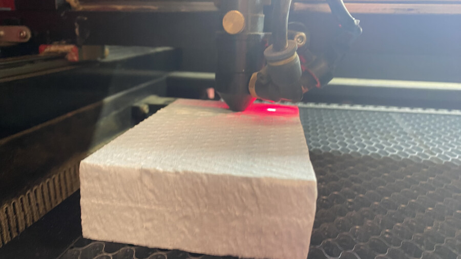
The laser cutter then performed a straight cut through the material. We made the cut in the center of the foam to obtain a clearer cross-section without needing to balance the parts later on the table.
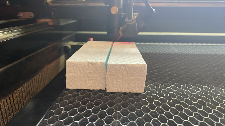
After cutting, we placed the pieces on a flat surface and marked the point where the beam appeared to be the narrowest.
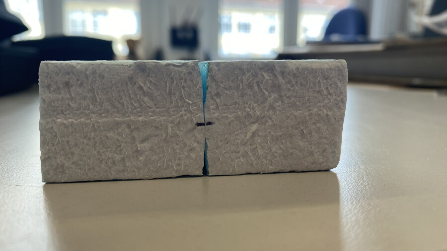
The final step was measuring the distance between the surface top and the marked focus point. It is crucial not to flip the parts, as this would result in incorrect measurements.
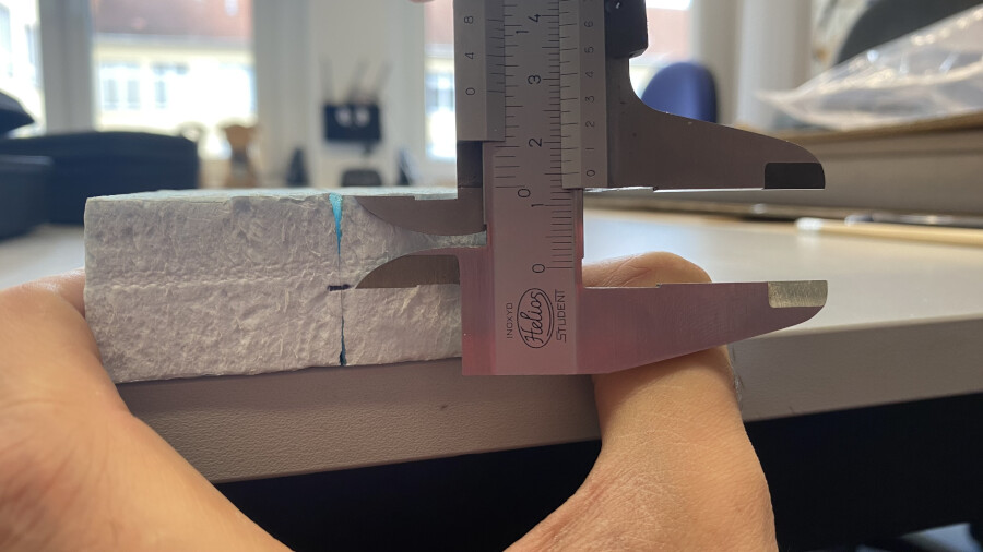
In our case, we determined that the narrowest point was 15 mm below the top surface, meaning the focus point is 15 mm beneath the bottom of our laser carriage. Our current acrylic focus gauge aligns the focal point 5 mm below the material surface. To optimize future cuts, a 15 mm focus gauge could be used, or, for cutting 3 mm cardboard, a focus depth of 16.5 mm to 18 mm might be preferable to position the focus at the top, middle, or slightly below the material surface. Initially, we forgot to create a new gauge, so both the kerf test and my personal parts were cut with the focus point 2 mm below the bottom of the cardboard and HDF sheets.
Power
The laser cutter has a maximum power output of 80 W at 100% power. However, since our laser tube is relatively old, its actual maximum output is likely lower. For cutting, we typically use power settings between 60% and 90%. Engraving is usually performed at power levels between 10% and 30%.
Speed
We generally avoid speeds above 300 mm/s, as excessive speed can cause significant oscillation. However, higher speeds may be used occasionally, provided the machine operates smoothly. If abnormal sounds occur, the process should be stopped, and the speed should be reduced. Typically, cutting is performed at speeds below 90 mm/s, while engraving speeds are higher.
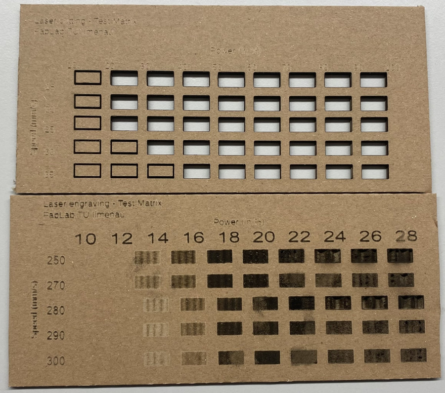
The following test diagrams for speed and power were created with a 15 mm distance between the laser carriage and the top of the material. As a result, the focal point was positioned directly on the surface of the cardboard. The top diagram shows the results for cutting, while the bottom diagram displays the results for engraving.
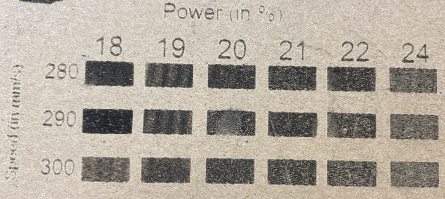
In this test, the optimal range of speed and power for engraving was repeated and verified.
Frequency
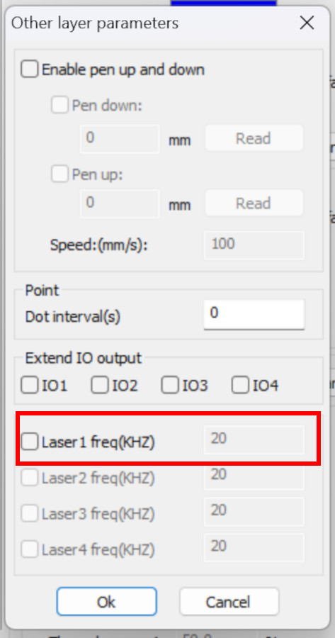
We discovered an option in RDWorks that allows us to set the laser pulse frequency. Previously, we had never adjusted or activated this setting. The default laser frequency is likely around 20 kHz, but we do not have precise confirmation.
Kerf
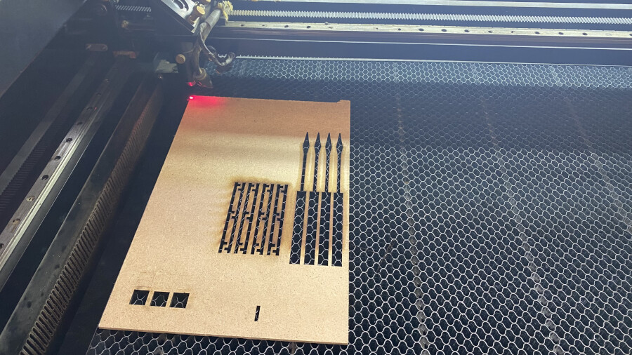
To measure the kerf, we designed a test where the laser cutter would cut 20 rectangles (later reduced to 10 for practicality).
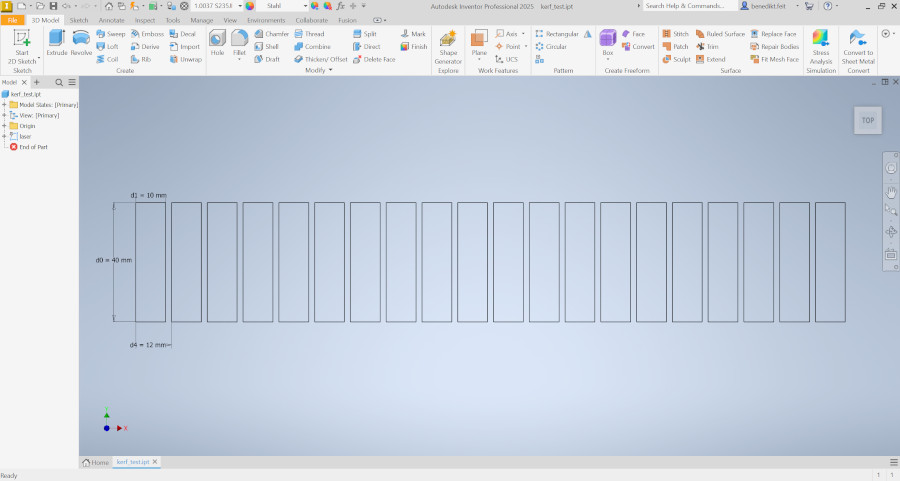
Our instructor, Ferdi, recommended using a material other than cardboard for this test, as cardboard layers can shift slightly above each other, affecting measurement accuracy. We used 3 mm HDF instead. Alternative materials such as acrylic or plywood could also be used. Since we had a scrap piece of HDF available, we proceeded with that.
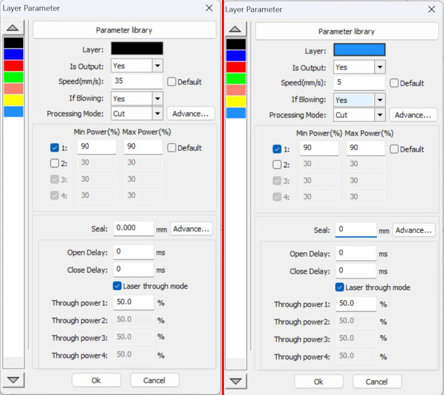
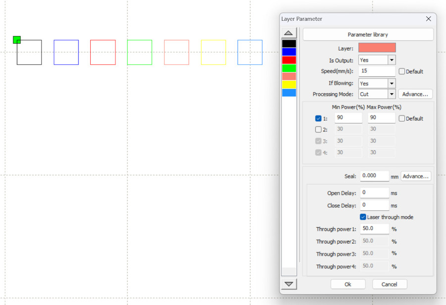
Before cutting, we needed to determine the appropriate power and speed settings. As mentioned earlier, our typical cutting power ranges from 60% to 90%. I decided to use 90% power and adjust the speed experimentally by assigning different layers to squares in RDWorks.
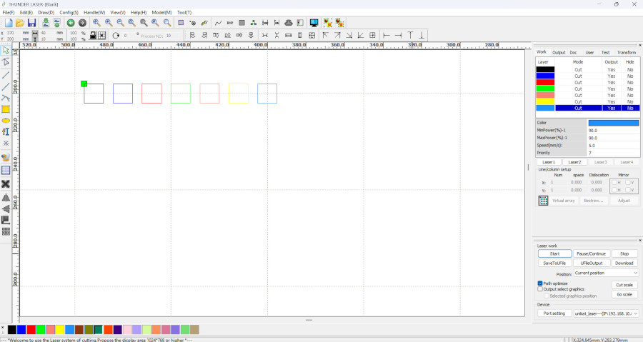
I tested speeds between 35 mm/s and 5 mm/s in 5 mm/s decrements, using seven squares for an initial classification.
The test results showed that starting from the fifth square, the parts were fully cut.
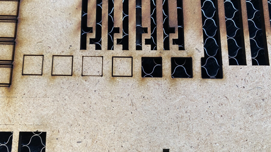
This corresponded to a speed of 15 mm/s.
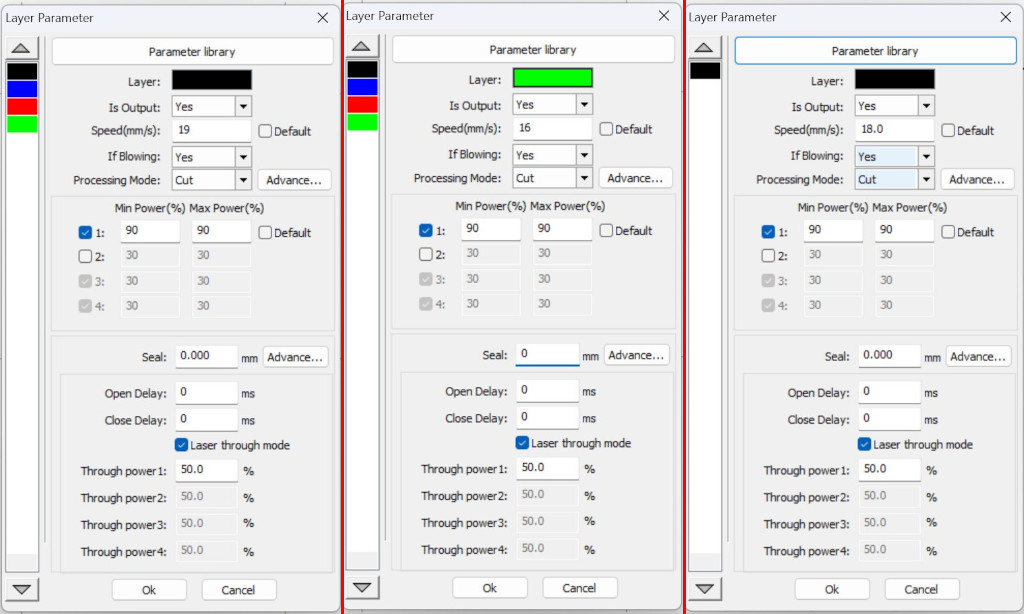
To fine-tune the settings, I repeated the test using speeds from 19 mm/s to 16 mm/s in 1 mm/s decrements. The optimal speed was found to be 18 mm/s, which was used for the kerf test.
The actual kerf test was then performed.
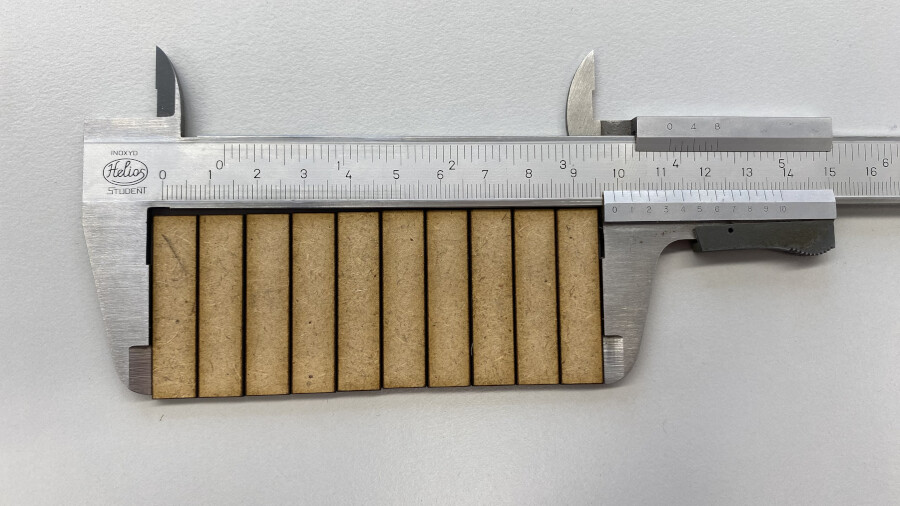
Finally, we measured all the cut pieces placed side by side. We calculated the kerf by subtracting the measured total length from the expected length and dividing the difference by the number of parts. In our case:
(10 * 10 mm - 99 mm) / 10 = 0.1 mm
Joint Tolerance
The cardboard material used is slightly compressible, making clearance joints unsuitable for this application, as the parts would fall apart. Instead, an interference fit works best. To confirm this, I designed a small test comb that allows testing in both directions. First, I measured the material thickness, which was 3 mm. Considering that we likely needed an interference fit rather than a clearance fit, I tested slot widths from 3.3 mm down to 2.5 mm.
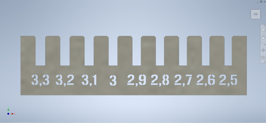
For the final cut, I decided to engrave the numbers rather than cutting them out.
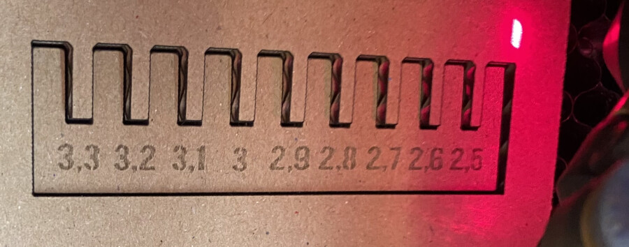
The engraving was slightly faint but still readable.
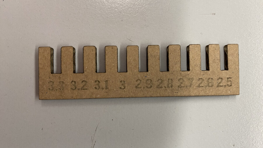
Using the finished test comb, I tested slot widths ranging from 3.3 mm to 2.5 mm.
The results showed that 2.5 mm provided the best fit, while 2.6 mm was slightly loose, especially upon repeated use.
Laser parameter used:
| HDF (3 mm) cut | Carton (3mm) cut | Carton (3 mm) engrave |
|---|---|---|
| 90% 18 mm/s | 60 % 29 mm/s | 18 % 300 mm/s |
Installing and Setting Up RDWorks
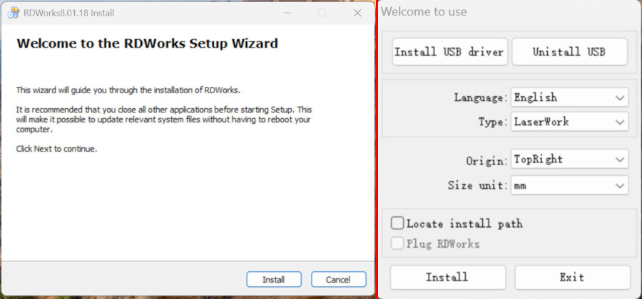
During the RDWorks installation process, a window similar to the one below will appear. Follow the on-screen instructions. After the general installation is completed, the following window will appear. The settings used in this example are shown. It is important to select the correct laser type. In our lab, the "LaserWork" type works correctly. The machine origin is set to the top-right corner, and we use millimeters (mm) as the unit of measurement.
After completing the installation, RDWorks will launch with the following interface. To establish a connection with the laser cutter, click on "Port Setting".
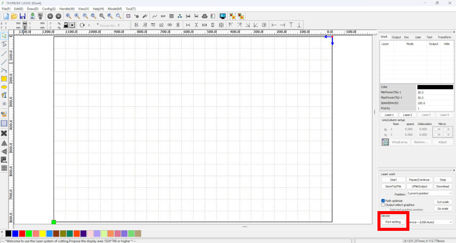
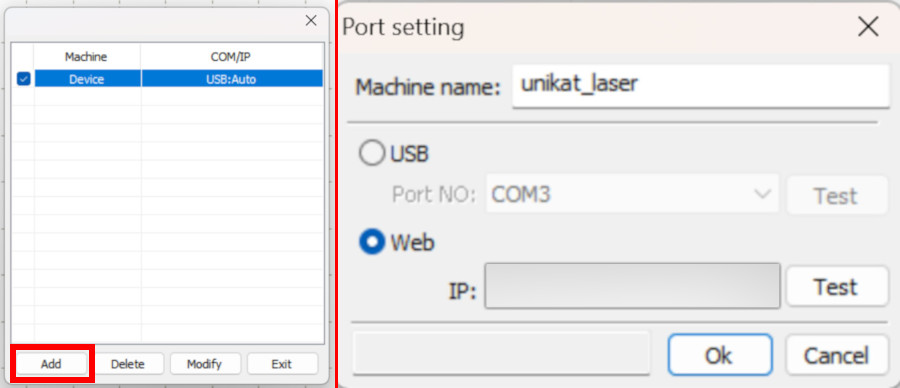
I chose to connect via the local network, so I selected "Web" and entered the IP address of the laser cutter. This address was obtained from another PC where the machine was already configured.
Finally, select the newly added device.
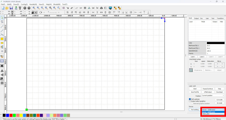
Initially, the bed preview in RDWorks may not display the correct dimensions. In my case, it appeared approximately 2.5 times larger than the actual size. To correct this, simply load a file into the software and press Start. This action will automatically adjust the bed size to the correct dimensions.
To prevent unintended laser activation, it is recommended to disable the laser tube beforehand. This way, the laser cutter will only move without emitting a laser beam. Once the file is sent to the laser cutter, you can also abort the process if necessary.