Week 03
Computer controlled cutting
Brief.
- Convert digital CAD designs into files to be cut via CNC
- Utilize parametric modeling to create press-fit model kit
- Utilize laser cutter and vinyl cutter for CNC process
- Explore laser settings and develop sample card of characteristics
Equipment at MIXFablab
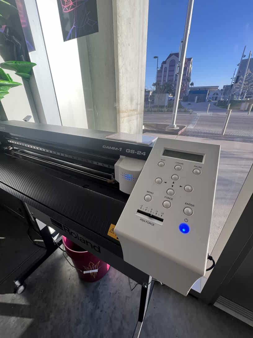
- Roland GS-24
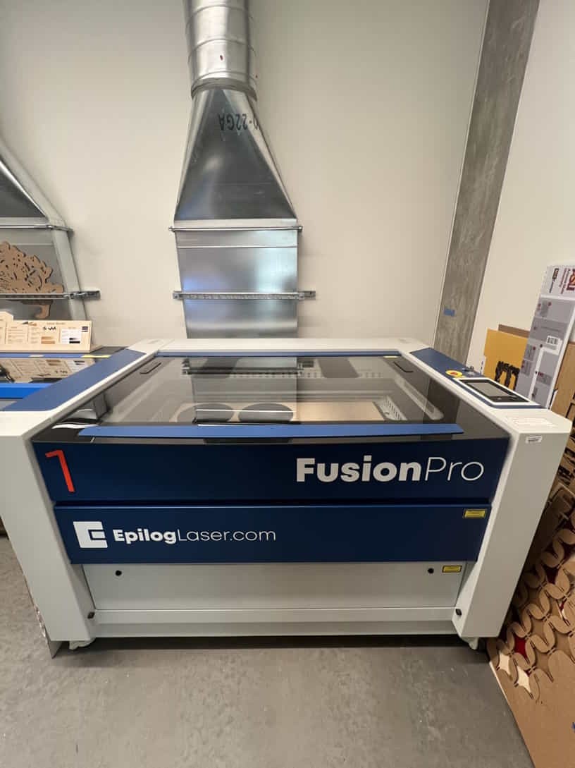
- Epilog Fusion Pro 48 - 150 watt CO2 laser
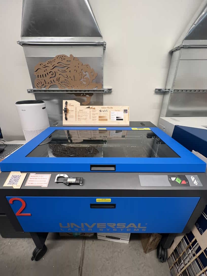
- Universal 6.75-75 watt CO2 laser
Helpful Hints and Resources.
Weekly Terminology:
Weeding: The process of removing excess, unwanted vinyl from your design. Think of it as removing the negative portion of your design.
Transfer Tape: Low tack tape applied to the top of your vinyl used when installing your vinyl design.
Kerf: The amount of material removed during a cut operation.
Tolerance: The amount of clearance or wiggle room between two mating surfaces, the gap between the two surfaces.
Resources:
Interesting topics, but didn't get a chance to fully explore:
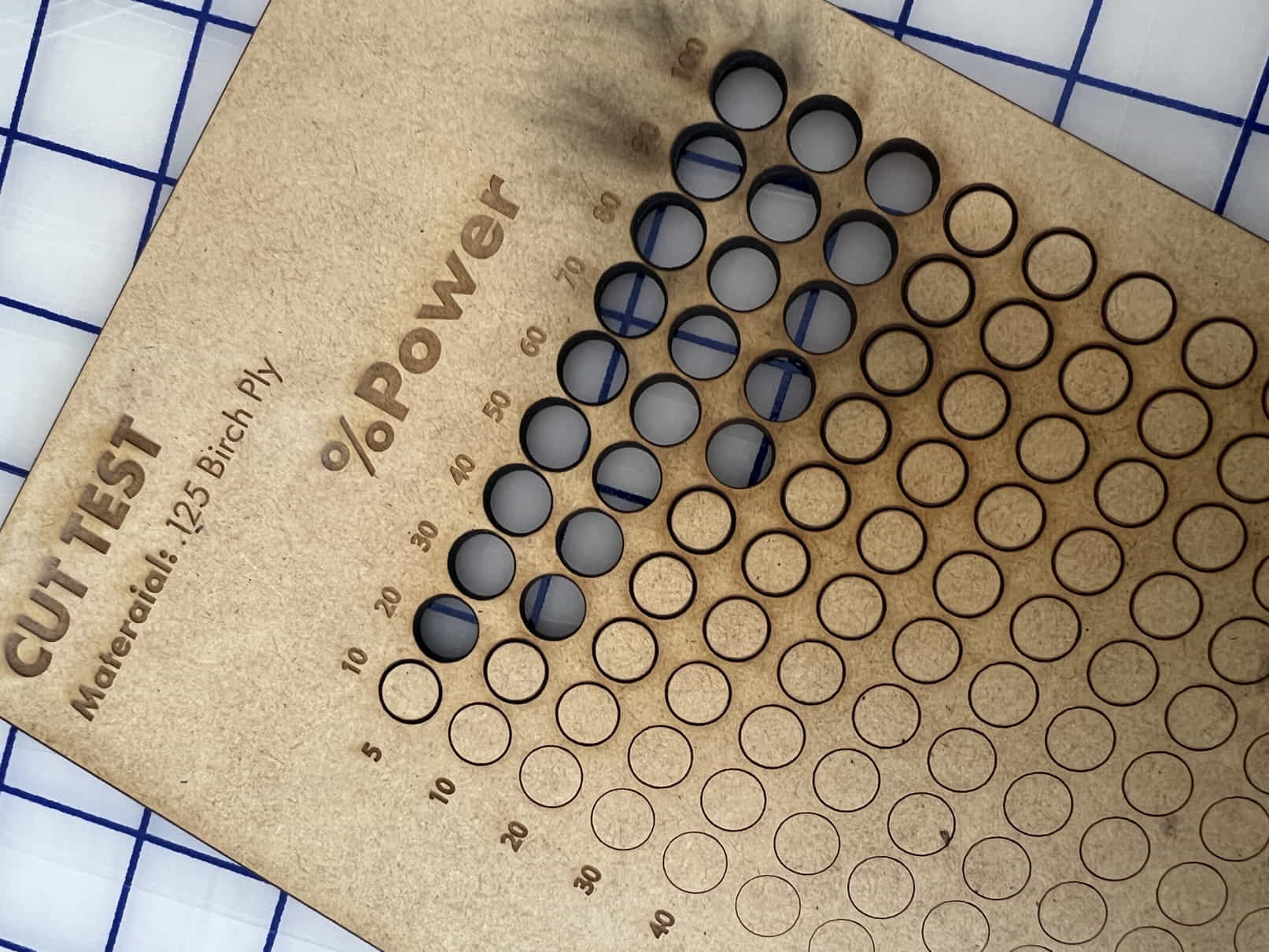
Laser test
For the laser test panel I decided to use the epilog fusion pro 48 which is equiped with a 120 watt laser source. I used the test file I created in adobe illustrator in the previous week. The test consisted of a matrix of circles. Along the x axis we had power and increased in increments of 10%. Along the y axis we had speed and increased in increments of 10% aswell as a starting reference of 5%. I was really suprised to see the results and it helped dial in the laser. Along with our tests we also discoverd that the laser alignment was off. The machine had drastically different cut settings when we comparing the top left corner to the bottm right.

Goal 1 - Parametric Laser Parts
My goal for this week is to utilize Fusion 360 to begin a parts library for press-fit puzzle kits. I’d like to develop a library of different parts so that we can host workshops and open lab times where the community can visit, explore the lab, and have a moment to play and assemble the various parts. It’ll be one part intro to FabLab one part art therapy.
The main need when developing the library is to be able to easily adjust different parameters depending on the material we have on hand. The plan is to utilize as much scrap material for these parts as possible. Given the thickness of materials will be variable, it is essential to be able to quickly adjust parameters parametrically so that the parts can be dynamic.
With this in mind, we will take advantage of Fusion's parameters function.
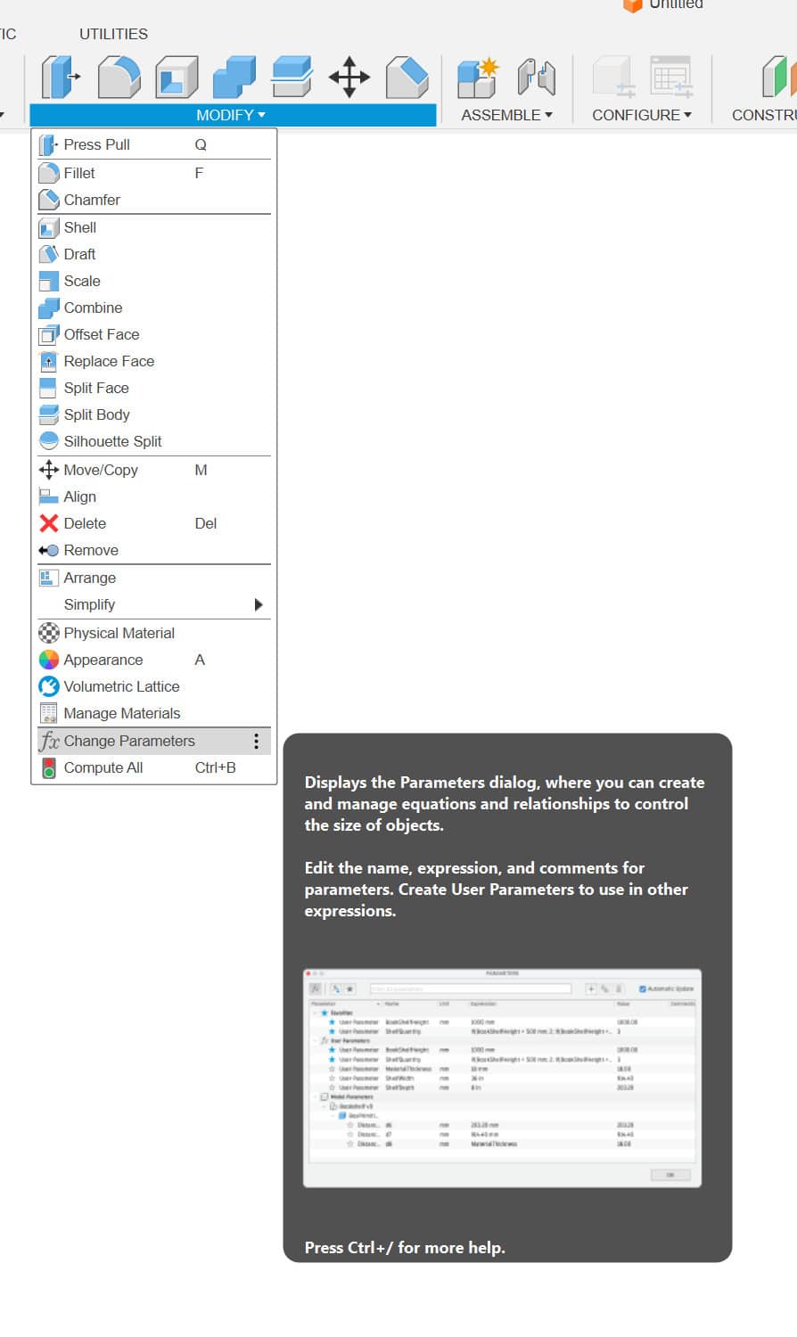
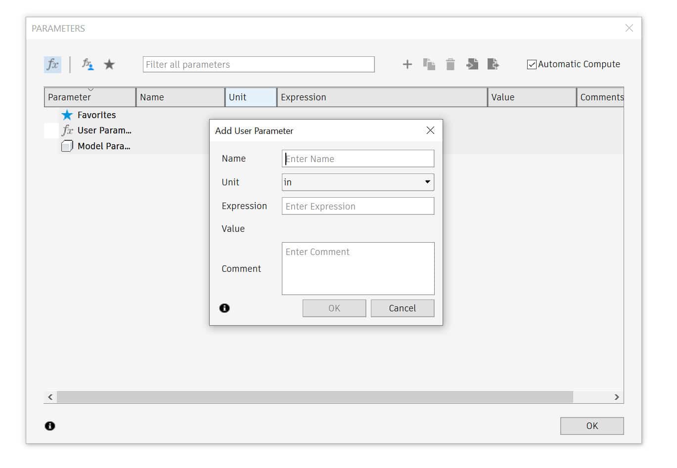
We can find the parameters button under the modify tab. Once open, we can click on the plus icon to begin adding in our own parameters for our current workspace. It's important to note that when using parameters, we will substitute a numerical value for an expression of our choosing. Think of it as a known variable in an algebra equation. Examples of parameters in my workspace were as follows:
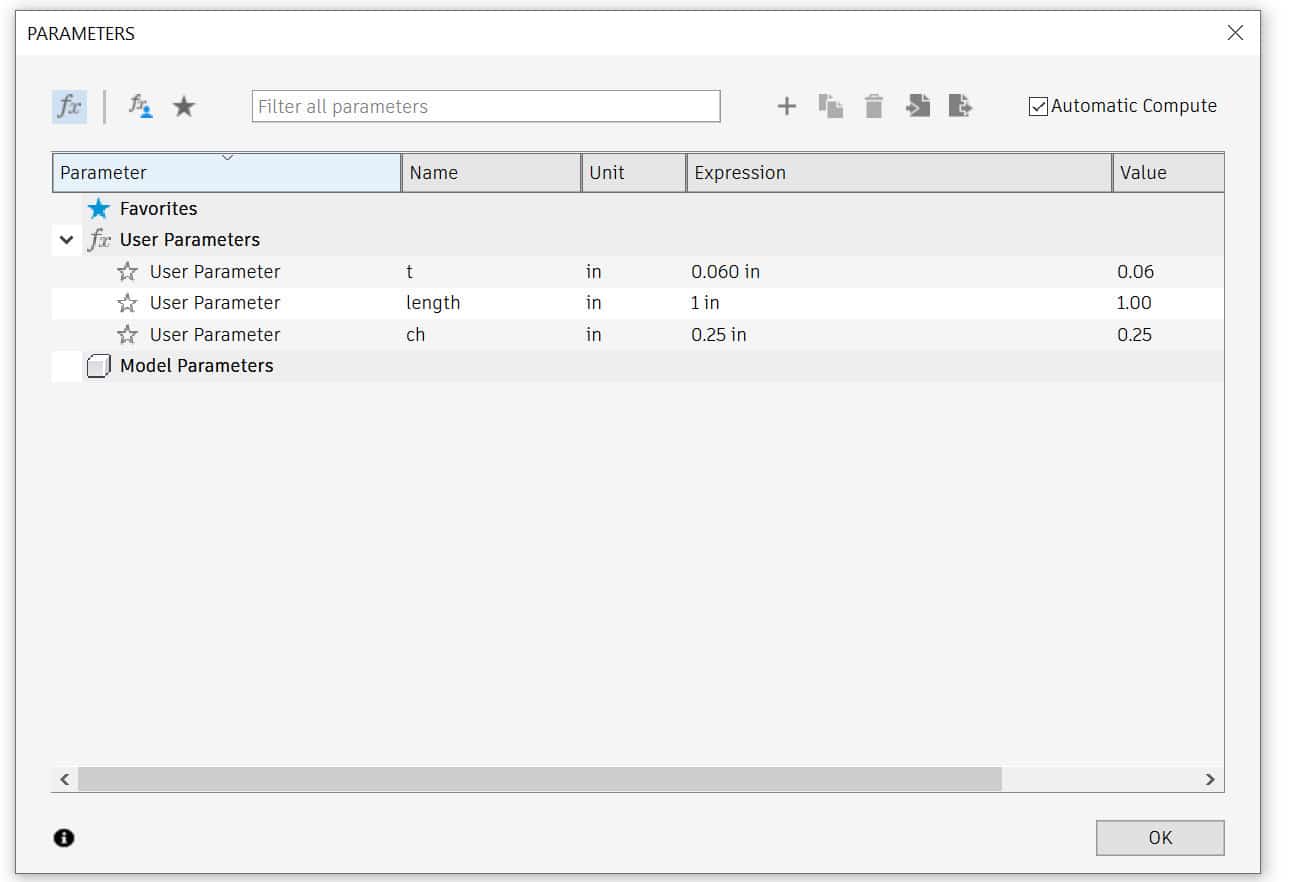
- t= material thickness
- sl= slot length
- ch= chamfer length
- width= width
- length= length
- Using vinyl cutter for intract large masks or stencils
- Vinyl cutter copper traces. Large scale as a wall sculpture or window treatment
- Scaling up laser cut pieces for the shopbot to use as arcitectural pieces.
- Incorporate more scale model building, to previz final project
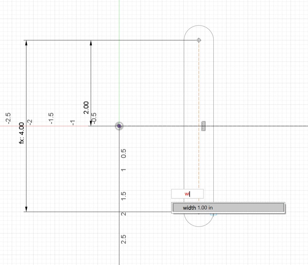
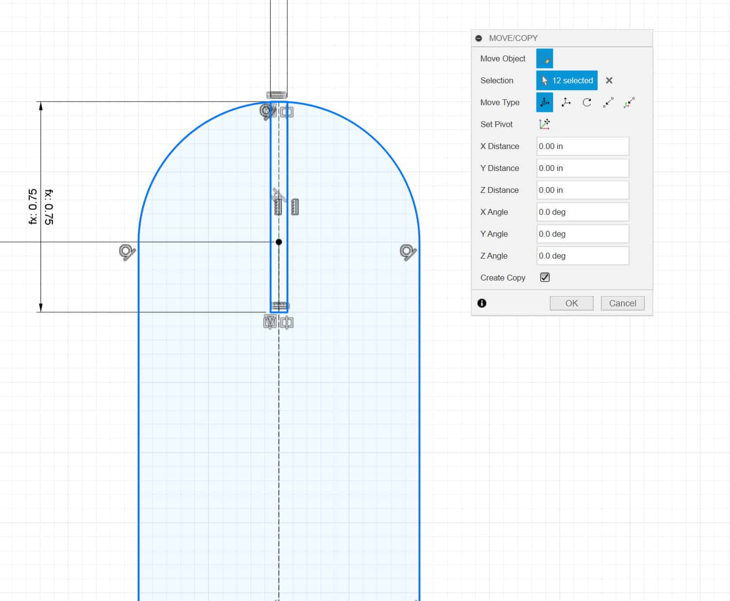
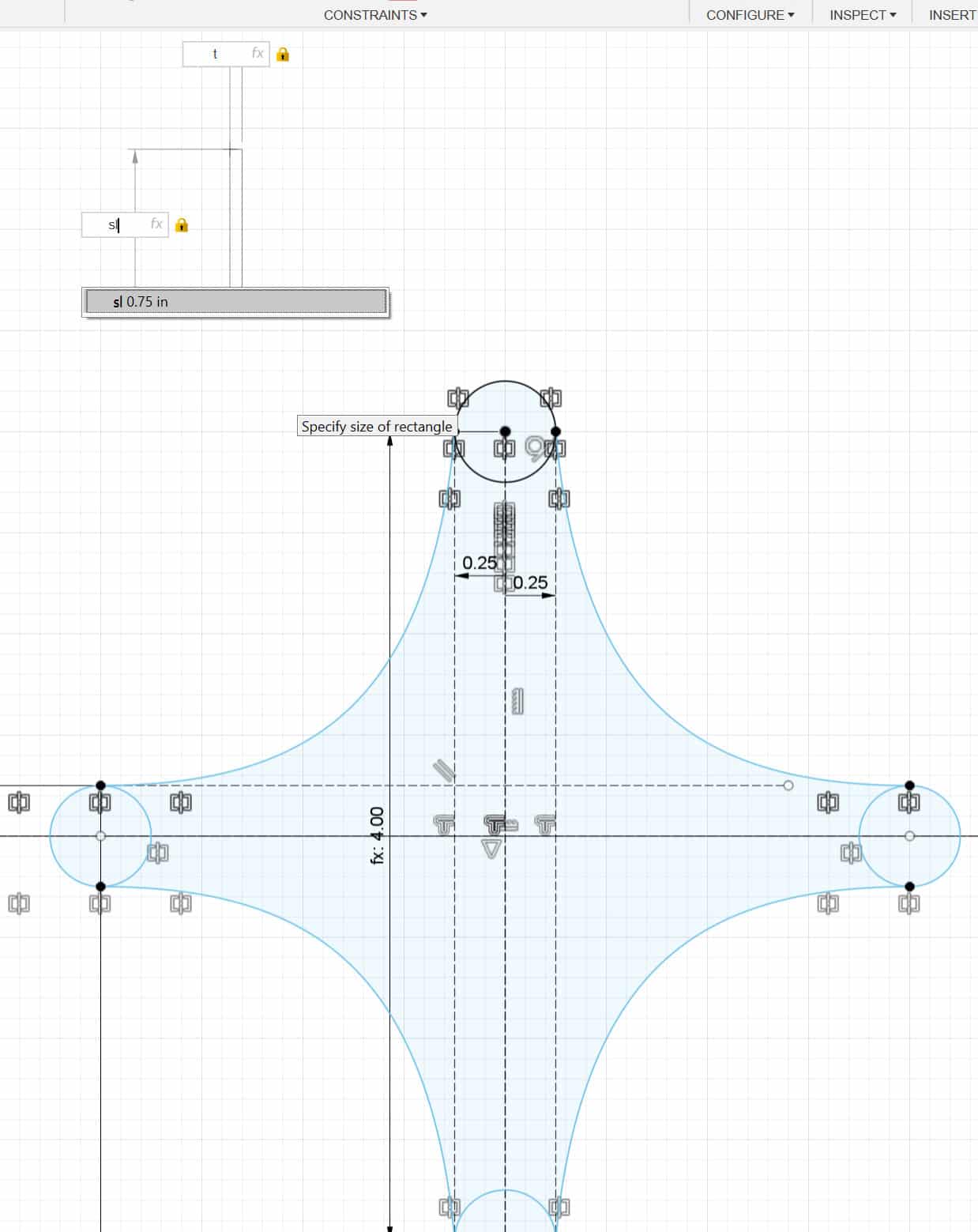
To utilize the parameters, all we need to do is type in the parameter expression in lieu of a specific dimension when we are sketching. Ex. type sl instead of ".75in" when we are denoting a slot length, or t when we are creating a notch to receive another part that we want to match the thickness of our material. We use the expression so we can easily update any values later. This allows us to make a change in one spot rather than make a change to every dimension across the entire workspace. In our case, we can change our "t" value to correspond to the thickness of material we are using for that specific run of parts.
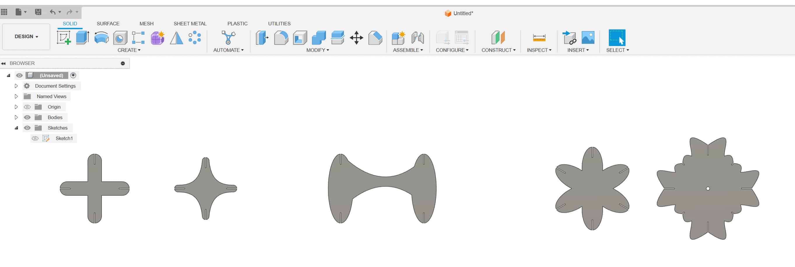
We can now begin sketching our part.
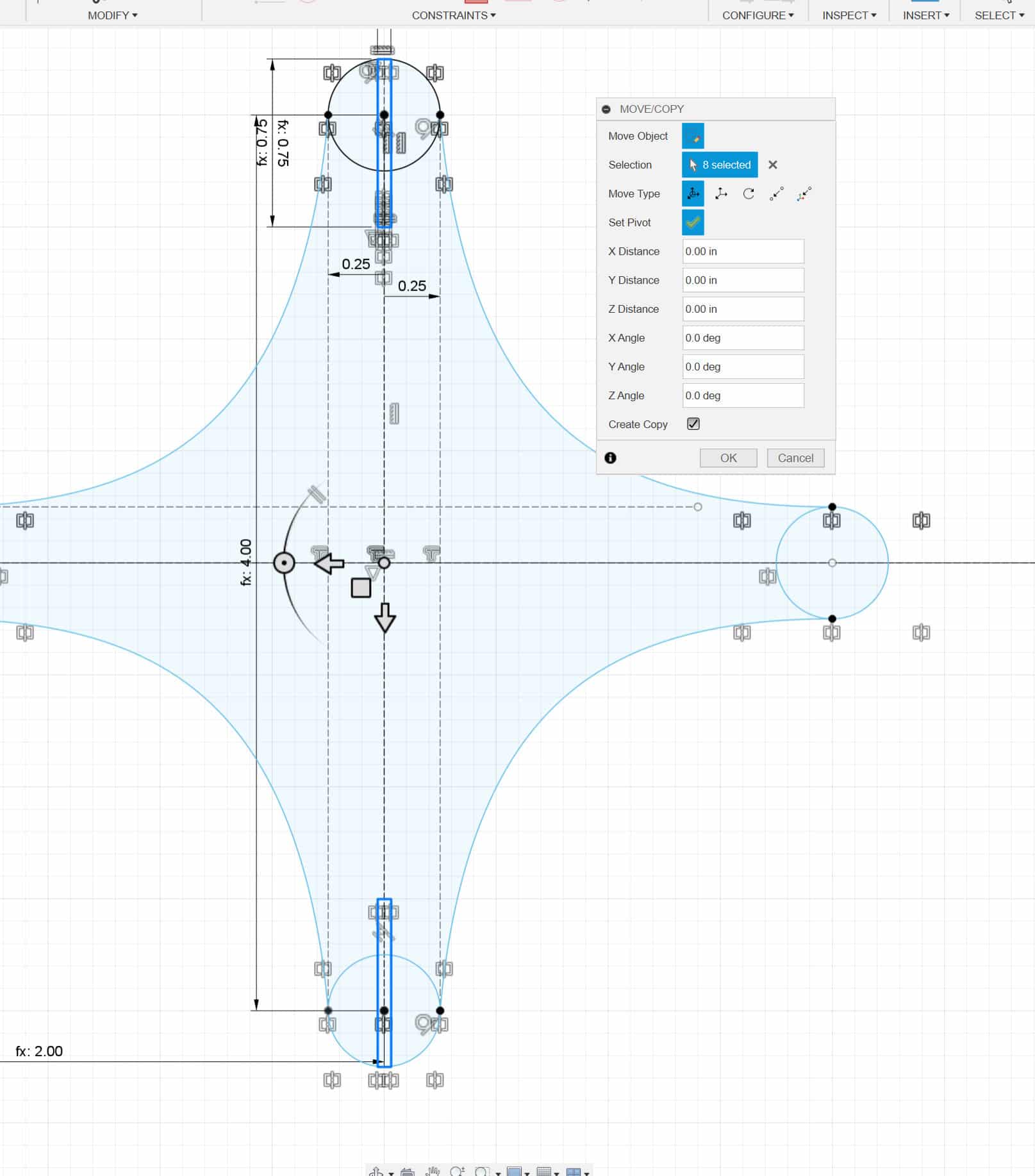
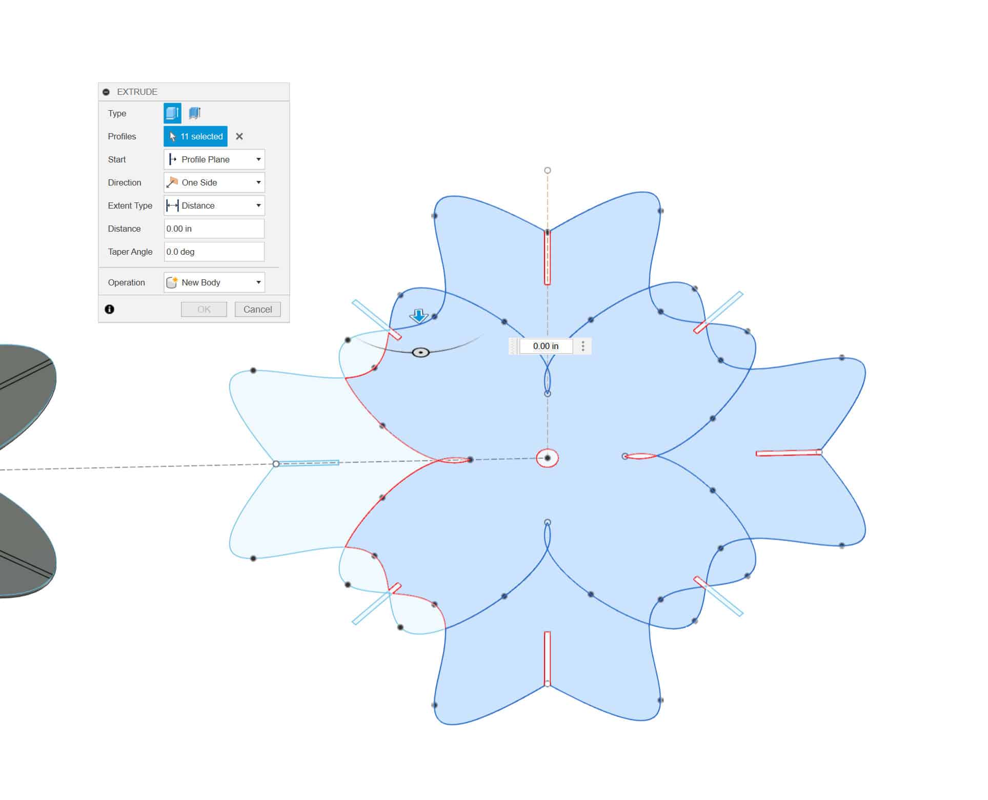
Now time to extrude and check my work by adjusting the thickness parameter. And...it worked ...kinda...

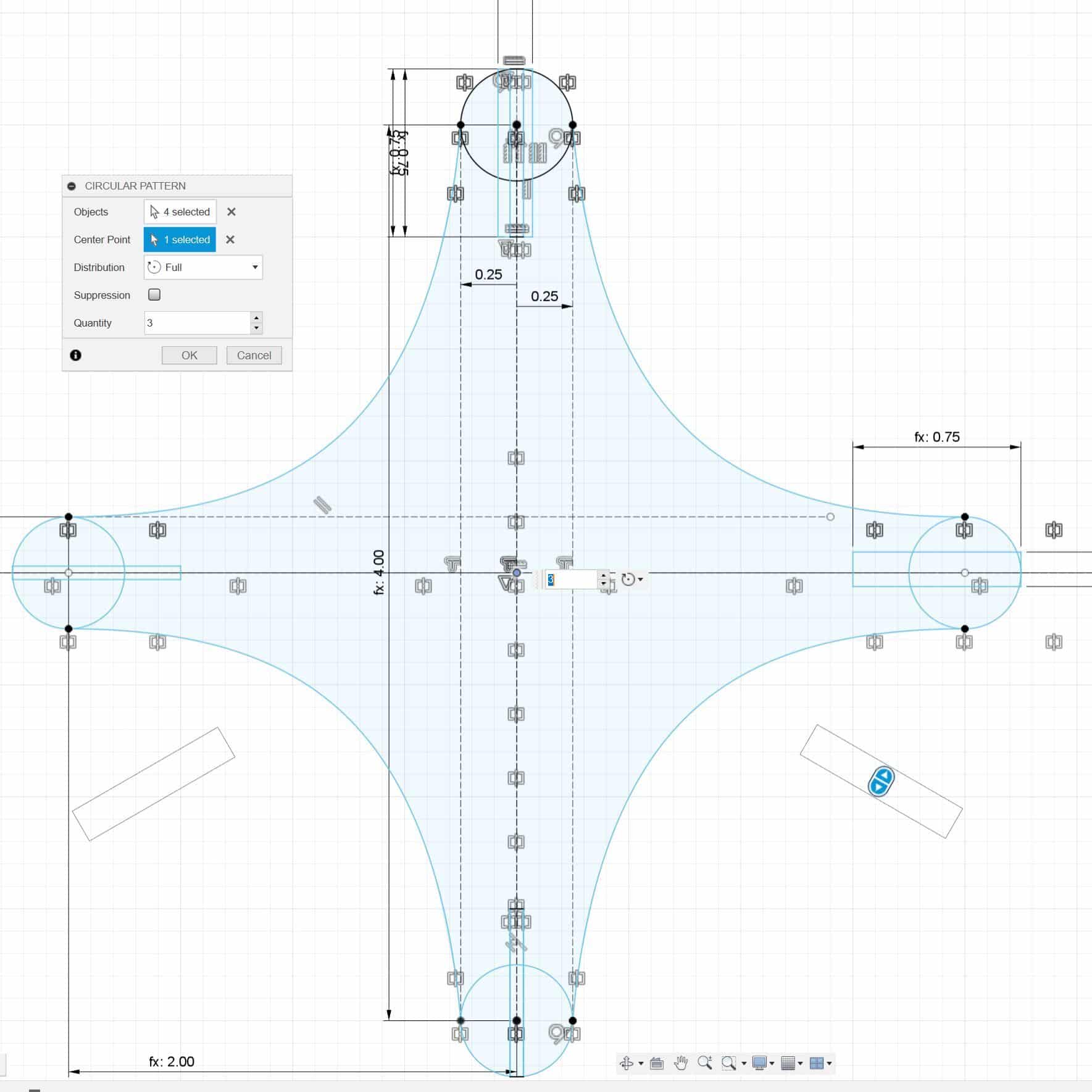
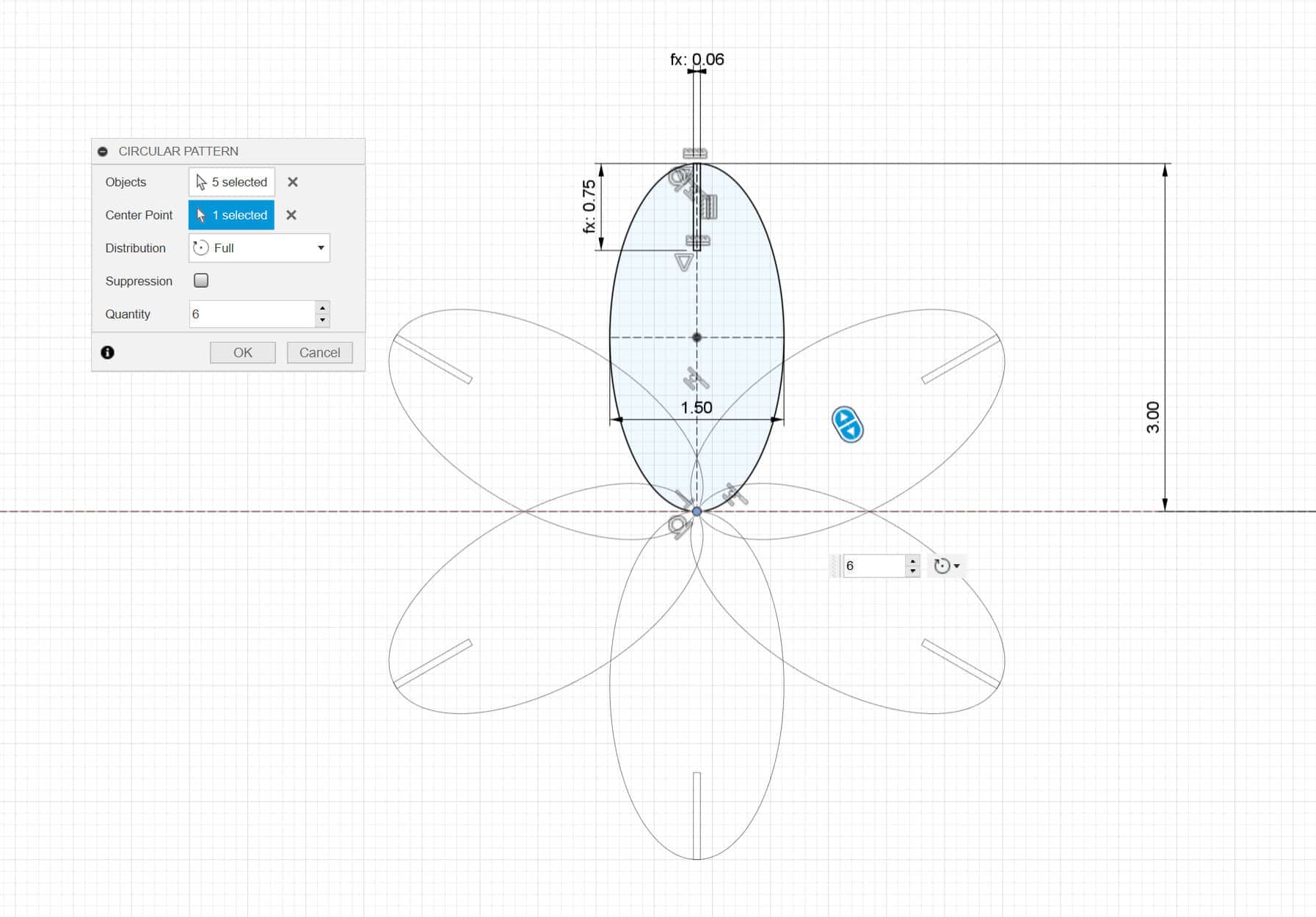
Depending on how I drew each part and how well I constrained my sketch ultimately determined how effective the parameter worked. A lesson learned in always having a plan and thinking through order of operations when adding constraints, dimensions, and parameters to the sketch. A quick fix was to use a circular pattern command for the slot feature instead of copying and mirroring the feature, which is what I did when I began drawing the part.
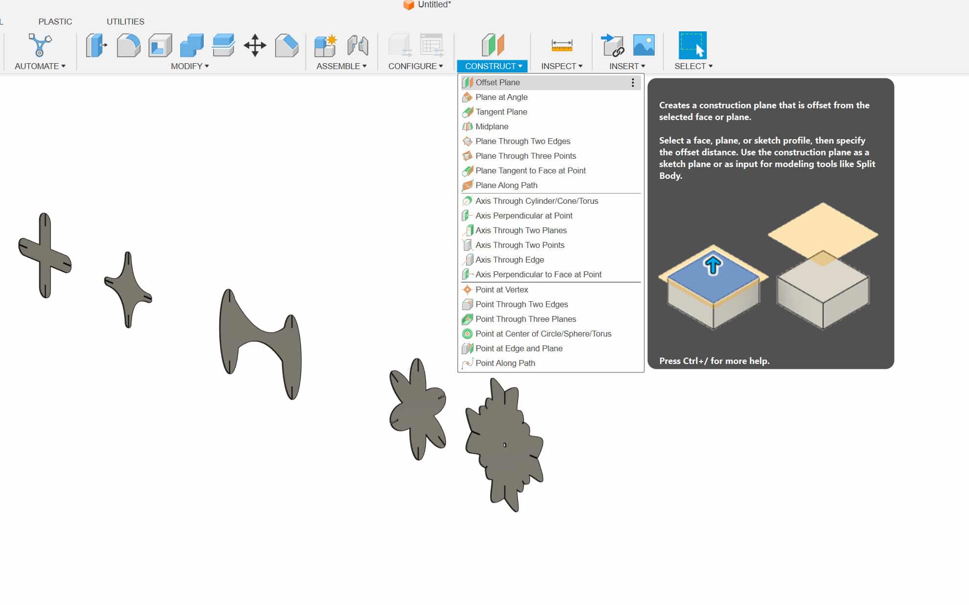
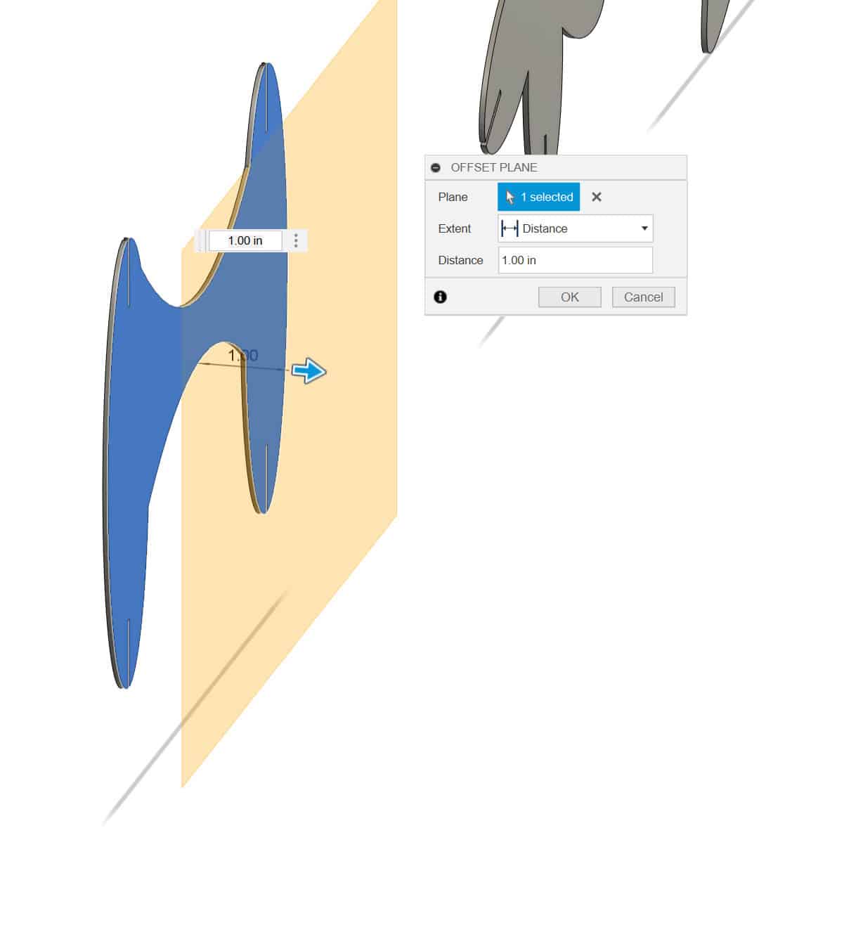
Next, I prepared my parts to export a .dxf file. The Epilog Laser I will be cutting with runs from print files sent from Adobe Illustrator. We will export a .dxf by projecting the outline geometry from the extruded parts. I find it cleaner to project the extruded geometry onto a new sketch. You could use the original sketch, but I find it to be cluttered with unnecessary construction and dimension lines that aren't typically needed when we move to the laser and work in Adobe Illustrator.
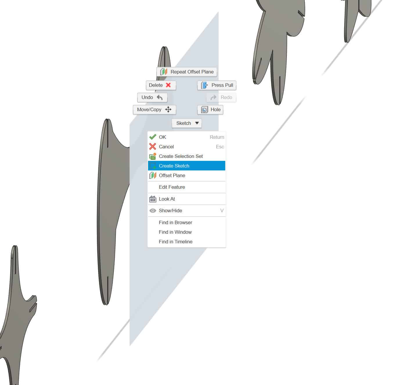
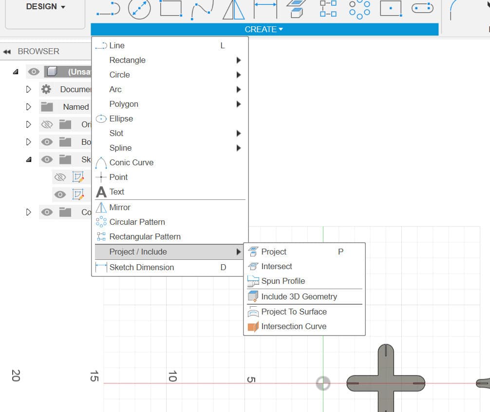
To begin, create an offset plane from the extruded part. Create a new sketch on that plane, and go to project and include. Select all geometry we wish to project.
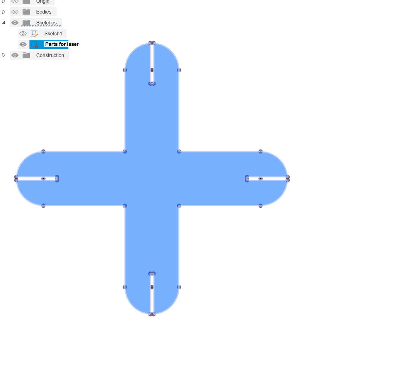
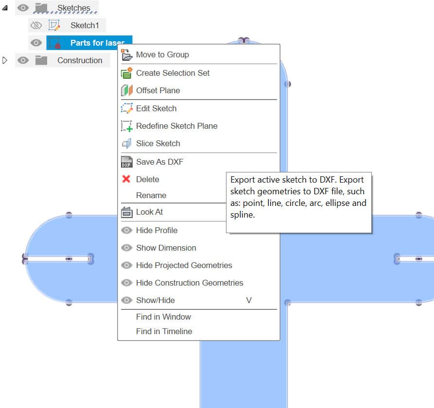
We can then locate the new sketch in our history tree (I find it useful to name the sketch to stay organized). Once located, right-click and select export as .dxf
Laser Time!
Laser File Prep
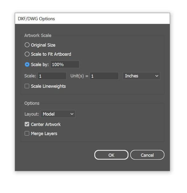
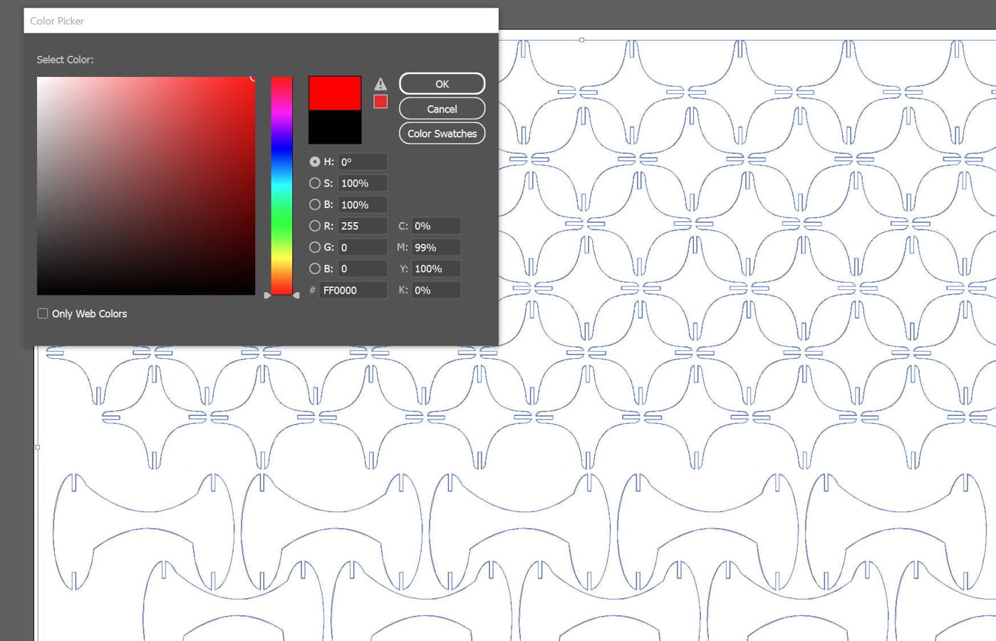
At the Mix Fablab, we ran all our laser jobs from Adobe Illustrator. We can easily import our .dxf file from Fusion to Illustrator. It will bring over units as a 1:1 ratio, so be sure to select the correct units you are working with. Next, we color code our cut lines by setting our stroke color to RGB red. Doing this will allow us to easily select vector cutting in the Epilog driver.
Cutting
Laser cutting went well. I opted to cut on the Epilog Fusion Pro 48. I cut with a power of 75% and a speed of 55%. The cuts were clean; however, the cardboard was quite bowed at the bottom corner, so there was a large portion that didn't cut all the way through and had to be finessed with an exacto knife.
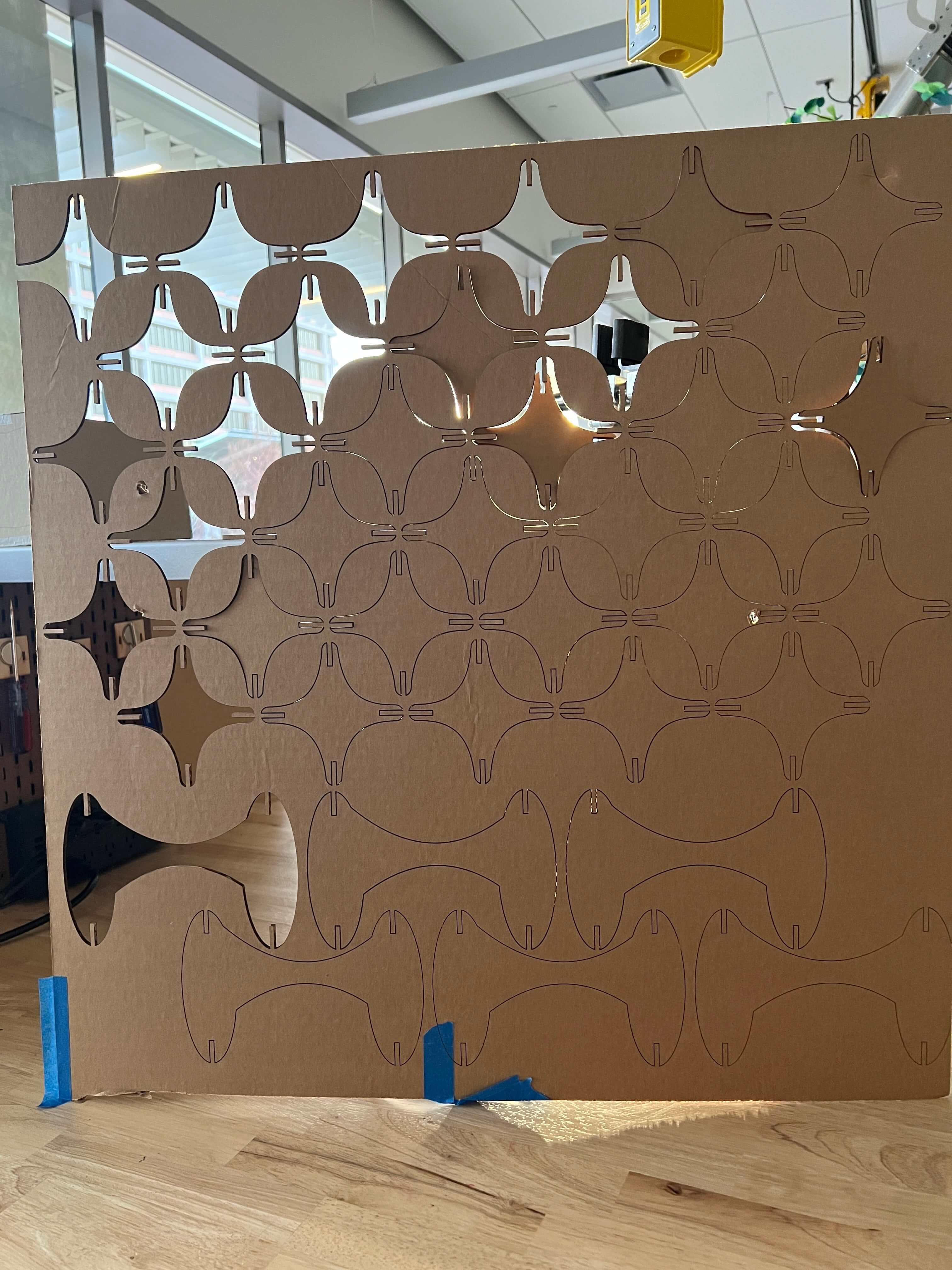
Assembly
Assembly was fun. Tolerances were nice and snug but not too tight, allowing for a nice sturdy press fit. I didn't add the corner chamfers, so the thin pointed pieces were mildly finicky to fit together.
Vinyl Cutting
Goal 2 - Vinyl Decal for Office Door!
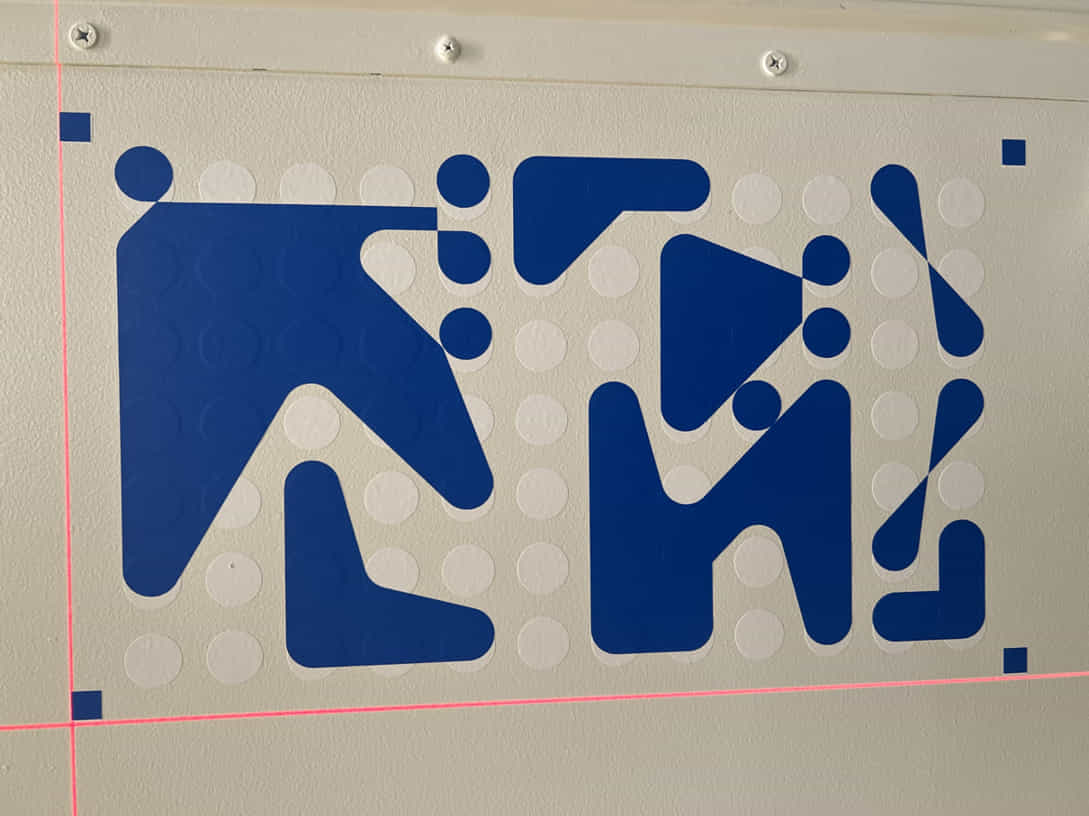
Inspired by Swiss graphic designer Armin Hoffmann, I wanted to create an abstract graphic to install outside my office door. After browsing around for some information, I found a really cool Hoffman tangent graphic creator. It was a fun therapeutic doodle/interaction with a web interface to create the graphic. I highly recommend checking it out (link in the resources section above). After creating the graphic, the program allowed for a direct .svg download. I downloaded all the ones I was happy with and imported them into Adobe Illustrator for final vinyl prep.
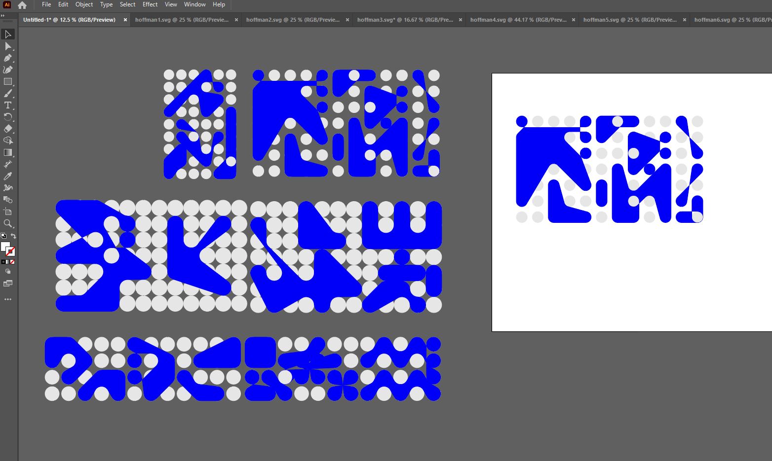
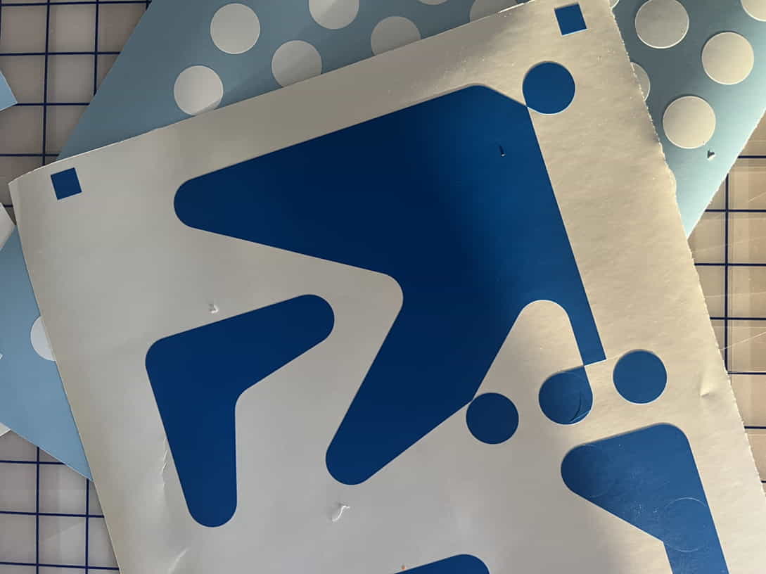
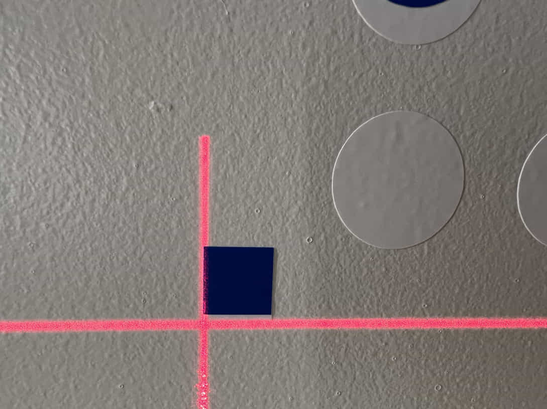
I wanted to create a two-color vinyl graphic. So, I Duplicated and separated out my image. One cut file would be the circles, and the second would be the blue blobs. I also added squares to all corners of the graphic to be used for registration purposes later.
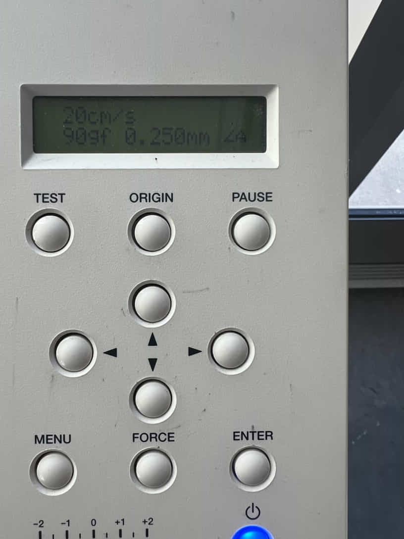
The Roland uses Cut Studio Pro as the driver to set up and cut with. I have found the best way to import a file into the software is to legacy save the file as a .ai version 8 file. From here, we can import our file into Cut Studio and send the plotter.
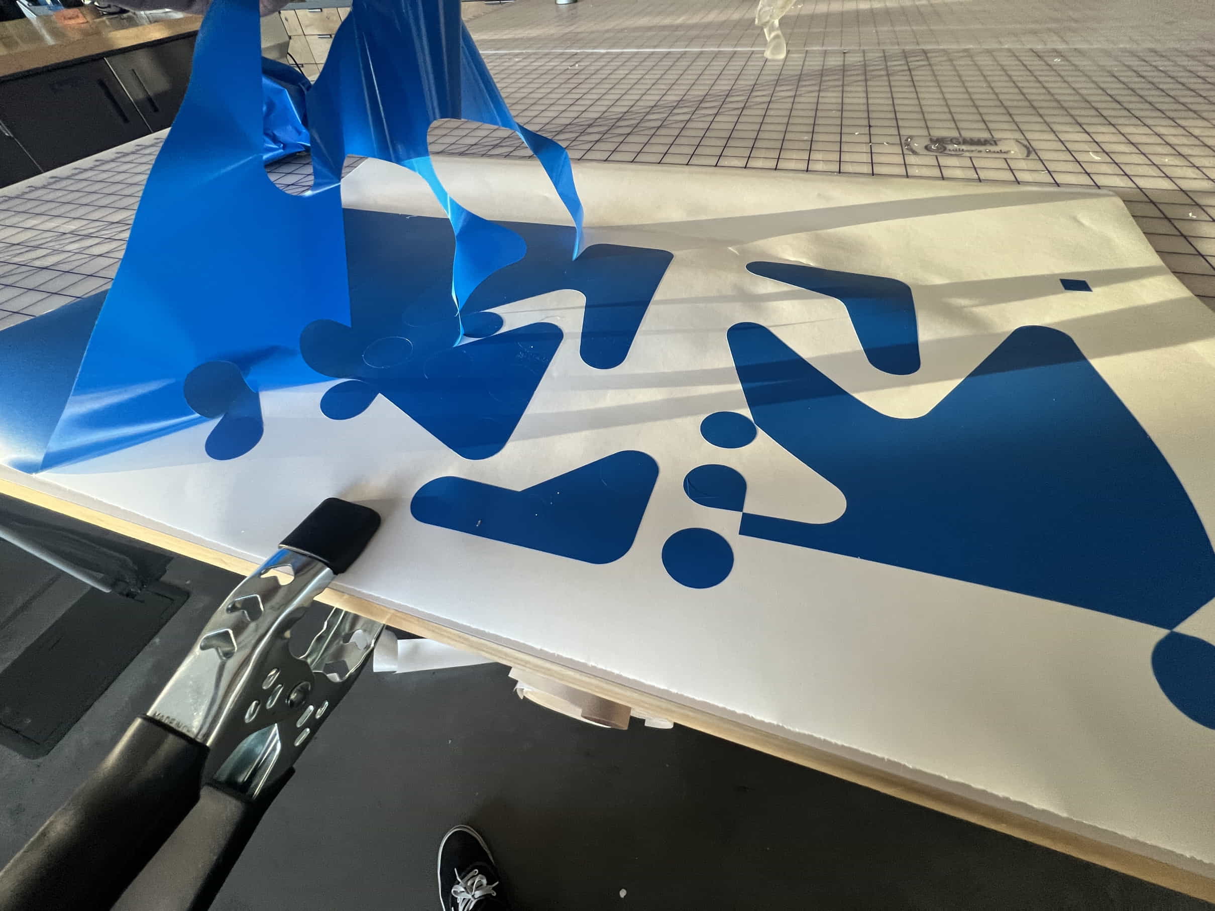
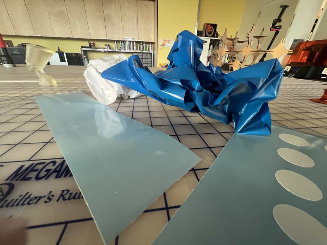
Once cut, I weeded the negative vinyl array to reveal my final graphic. Pro tip - clamp your vinyl to the table so you have more free hands to help peel up the vinyl.

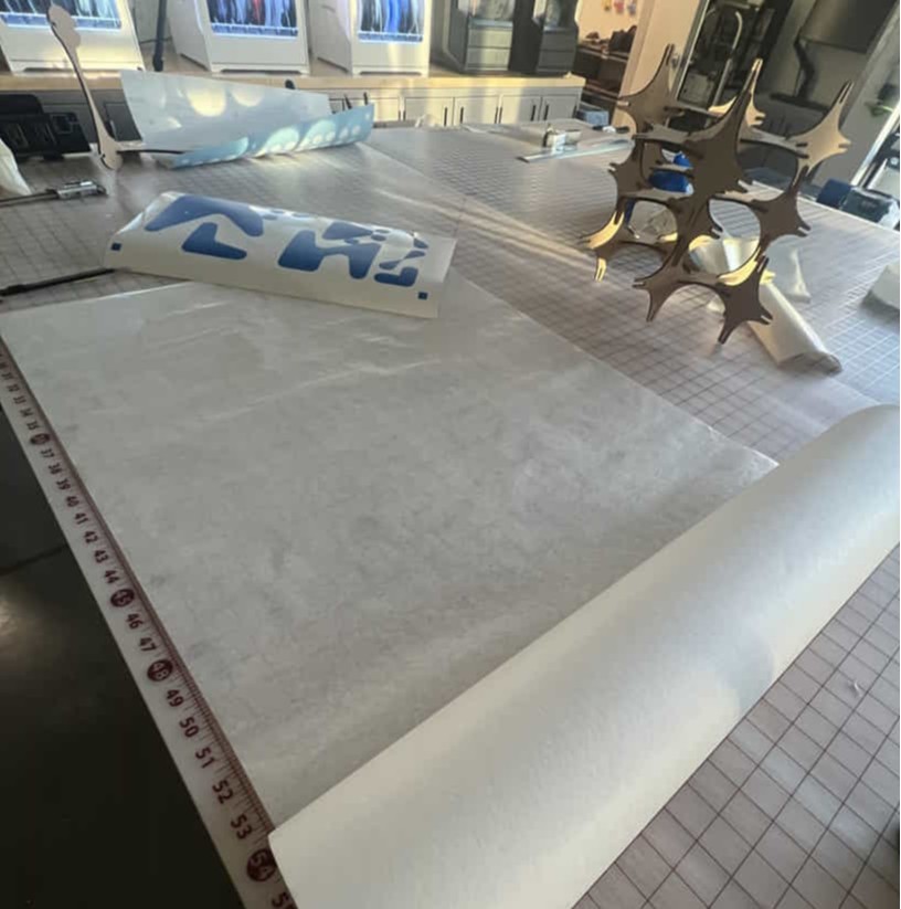
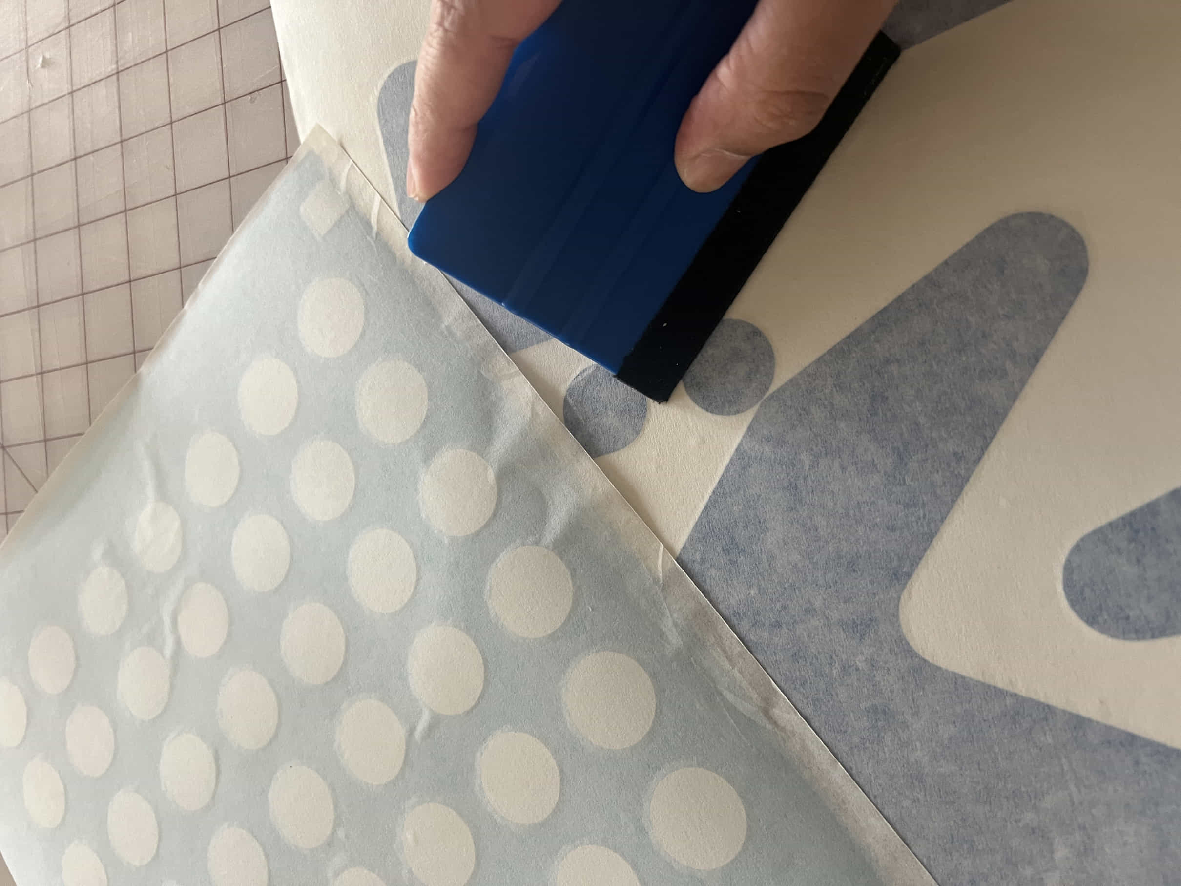
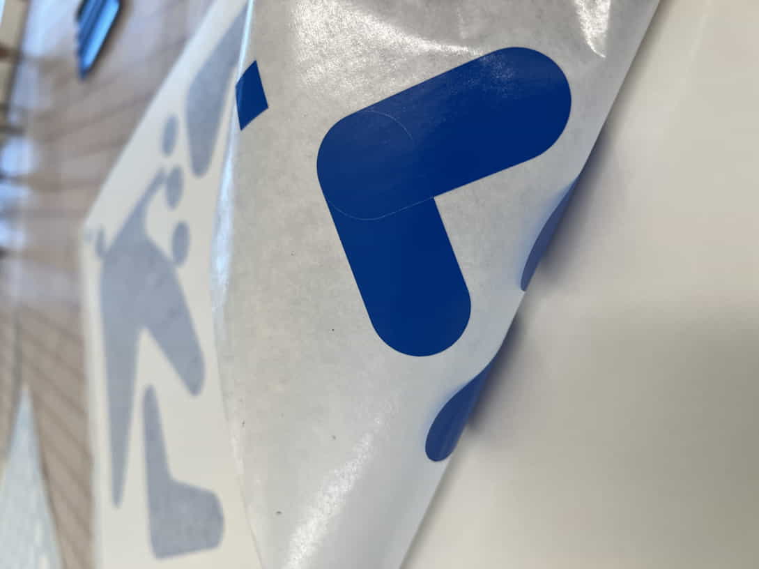
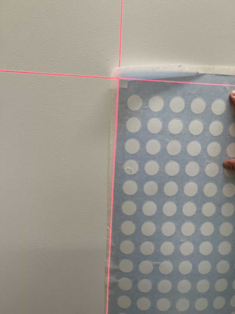
Then I applied transfer tape to the front side of the vinyl; this allows us to peel the graphic from the carrier sheet, revealing the sticky side of the vinyl so we can apply it to our substrate. I found it useful to roll out the transfer tape and place the vinyl face down on top of the tape. Once tacked in place, use a squeegee to apply firm pressure to ensure it lifts when you peel up.
Using a laser level to ensure levelness, I applied the graphic to my office door. Utilizing the squares on each corner, I was able to register both graphics on top of each other. Since the first graphic to be laid down was white, it was hard to see exactly where to place the blue, but I got it close enough.
Conclusion
Pareametric modeling is an incredibly powerful tool, that i'll definetly incorporate into my process in the future. It requires some initial effort in the front end but provides room for changes long term. Its especially useful when desiging around a parameter or object that you don't already have or unsure of exact dimension i.e thickness of material being used or designing an enclosure around an electronic part that is yet to be determined.
Some things i'd like to explore moving foreward:
files
Check the link below to try for yourself!:
parametric parts for laser.svg3d models for paramtric parts
vector files for paramtric parts
hoff_test 2color_vinyl.svg