Assignment
group assignment: • characterize the design rules for your in-house PCB production process • submit a PCB design to a board house Link to the group assignment individual assignment: • make and test an embedded microcontroller system that you designed • extra credit: make it with another process
Milling
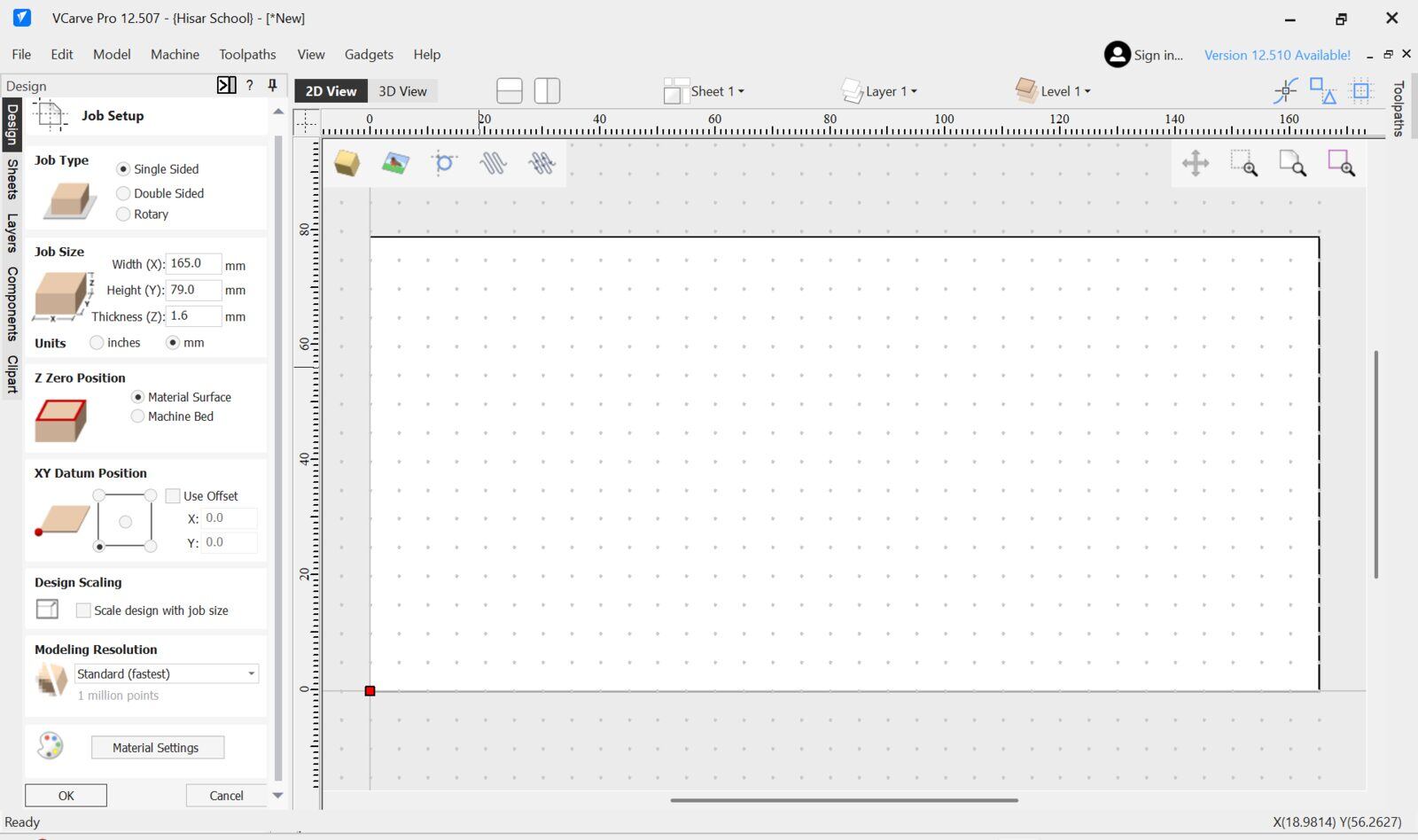
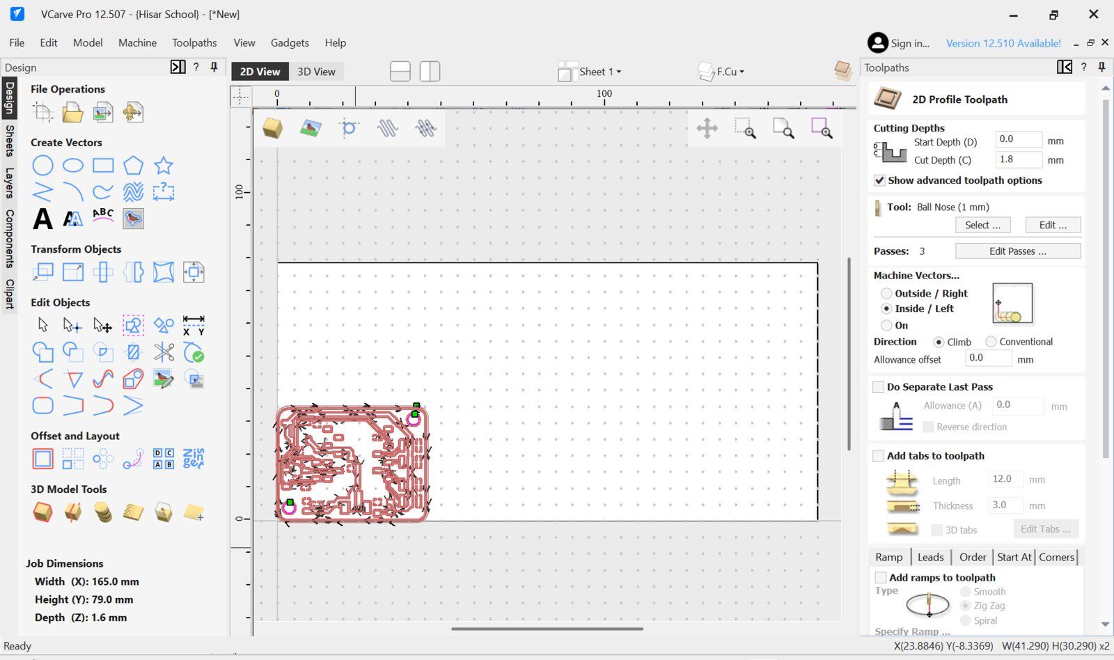
I started by opening a V-carve file then configuring the workpiece and datum.
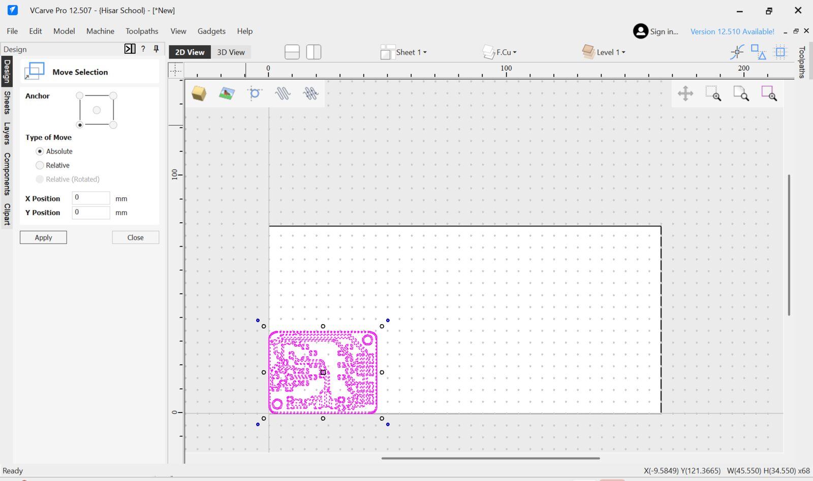
I then imported my DXF file that I exported from KiCad and moved it to the left bottom where my datum is of the canvas using the absolute move function.
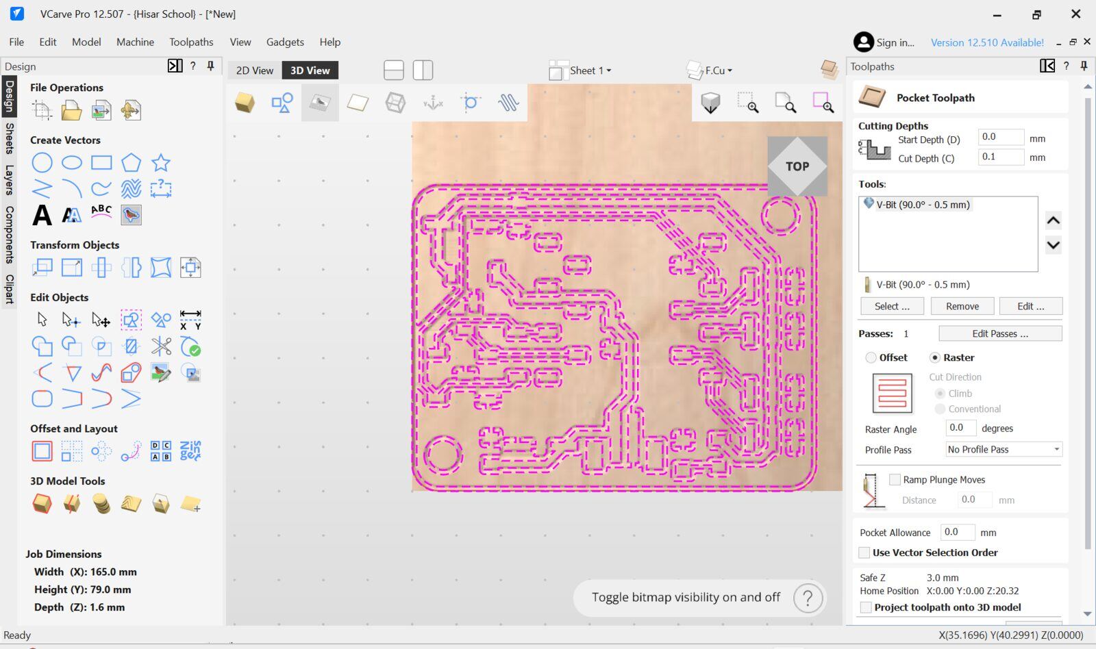
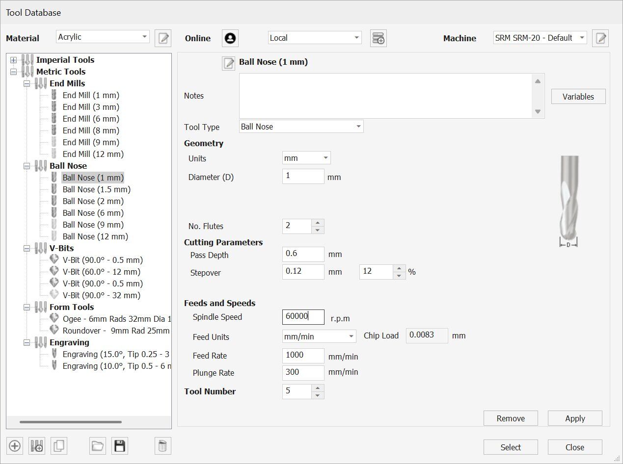
Then I selected the traces to be pocketed and selected the v bit I am going to use I will be using a 0.2-0.5 mm 90 degree V bit to engrave the traces using a 0.1mm pass depth.
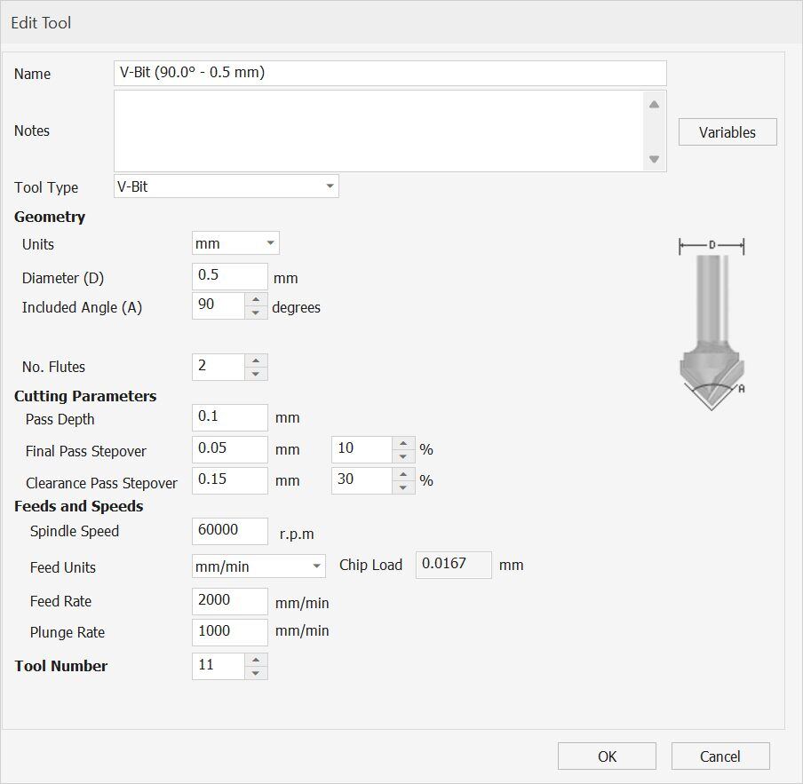
Here is the full tool config I will be using our Derin Motion PCB milling machine which has 2000 mm/min max feedrate and 60 000 rpm spindle so I configured the bit according to that.
Then for the Holes and the Edge cut I will be using a 1mm endmiil. I used a inside(mills inside the selected vector used for inner cuts) profile toolpath for the holes and an outside(Mills outside the selected vector used for outer cuts) profile toolpath for the edge cut
Here is the 1mm end mill bit config I used
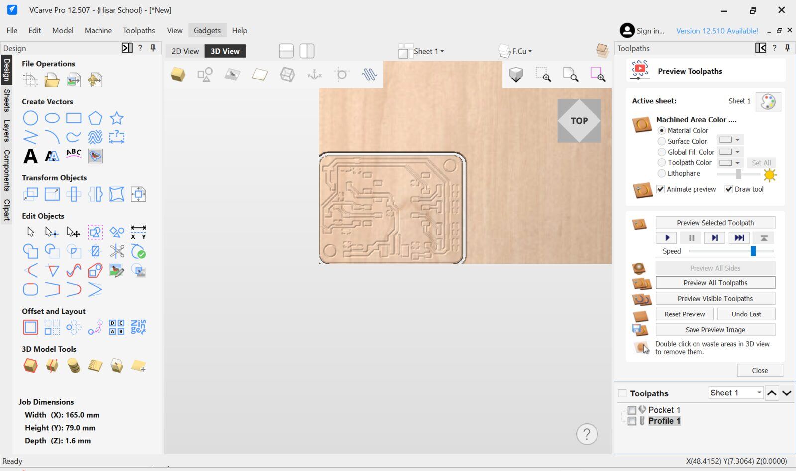
Then I previewed the toolpath using the preview function of Vcarve.
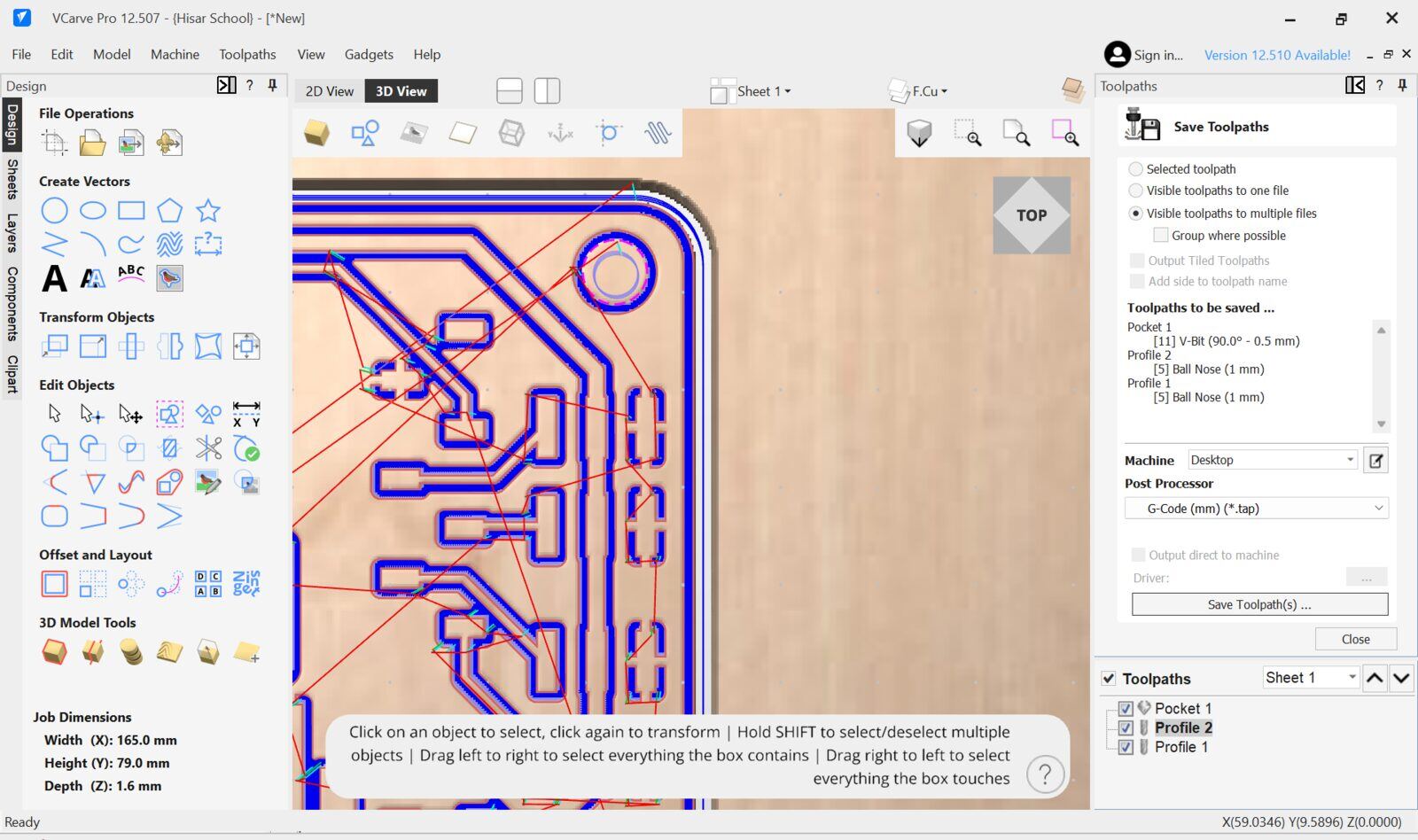
since everything looked fine I saved the toolpaths into separate files.
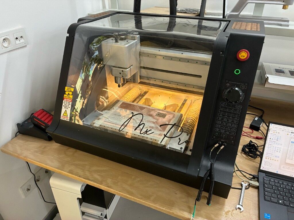
This is the DerinMotion PCB milling machine that I mentioned

It has a vacuum hold down which is powered by this shopvac
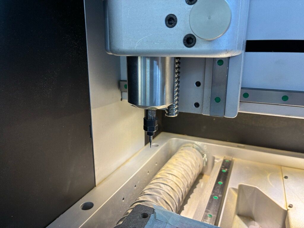
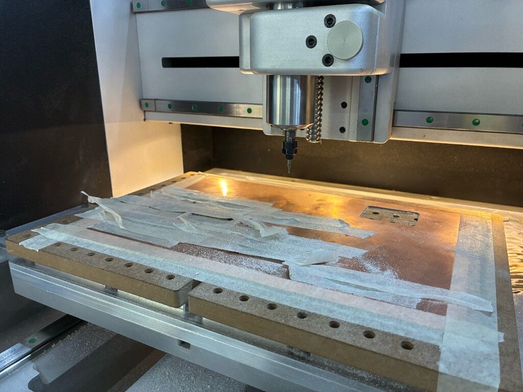
I first loaded the v bit to the collet then Zerod my XY to the bottom left of the part of the copper that I wanted the pcb to milled on then Used the probe function to Z zero
This is the probe interface it is used by connecting a crocidile clip to the bit and an other to the pcb board and automaticly setting the Z zero when the tool bit touches the board
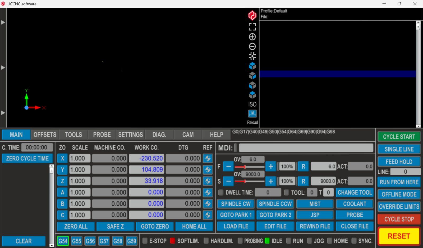
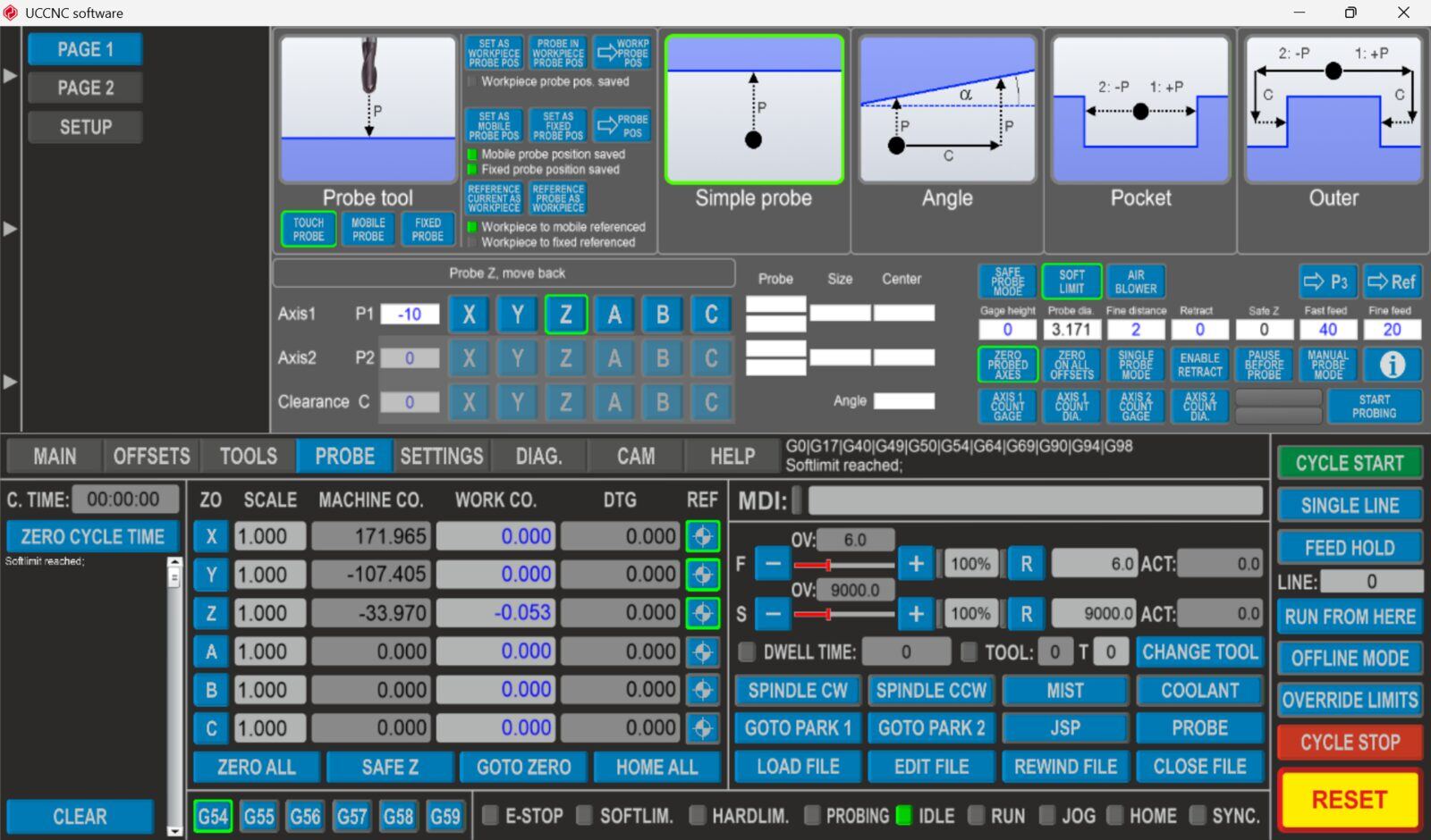
This is the UCNC work coordinate setting interface you basically control the machine XY position via arrow keys and clicking on the axis keys(X, Y and Z) to zero them.
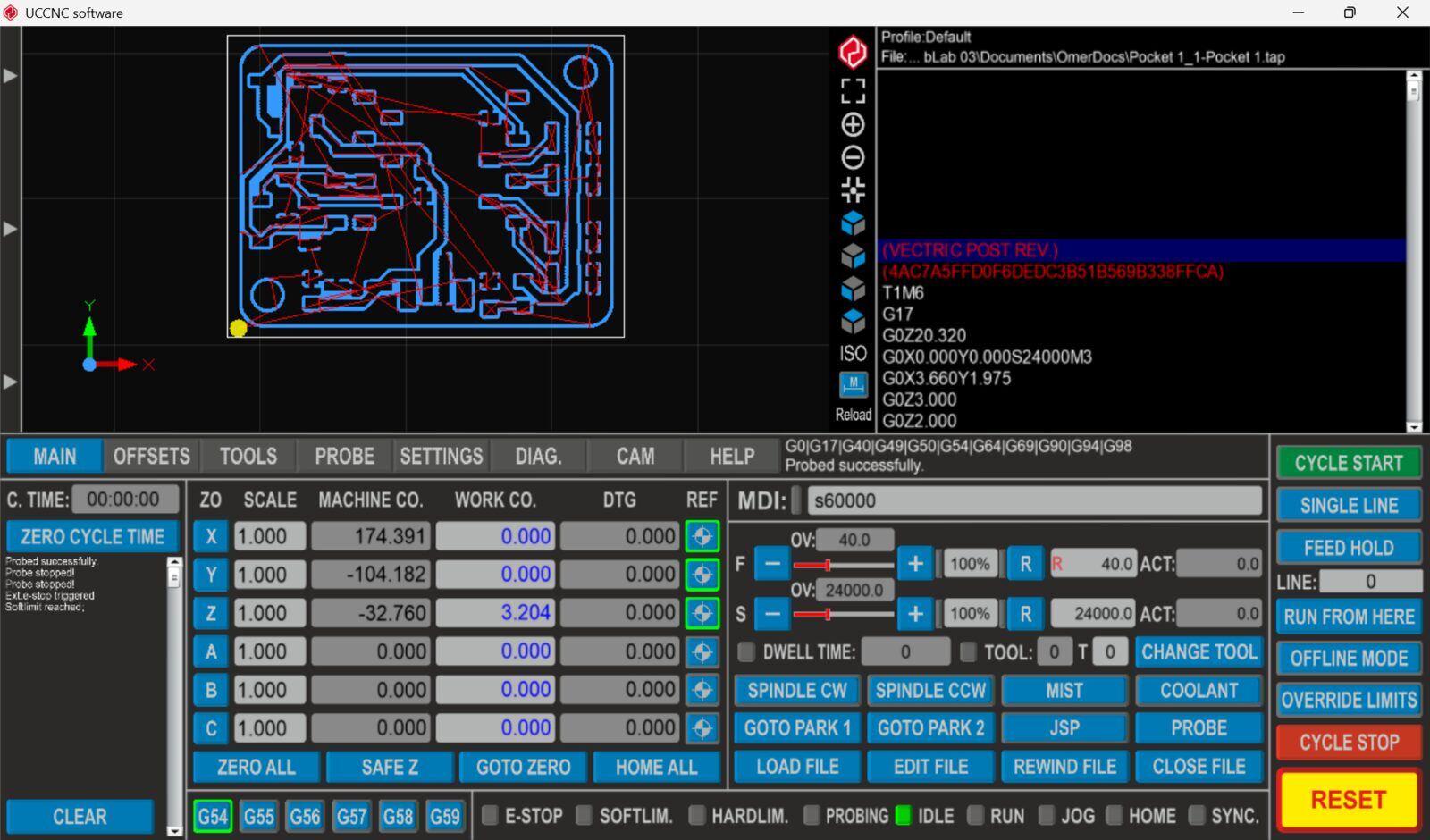
Then I cycle start to start milling the
Milling Video.
I repeated the same thing for the 1mm end mill. and started milling
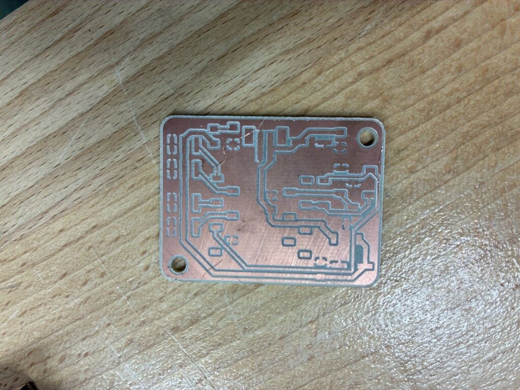
This was the final result
Soldering
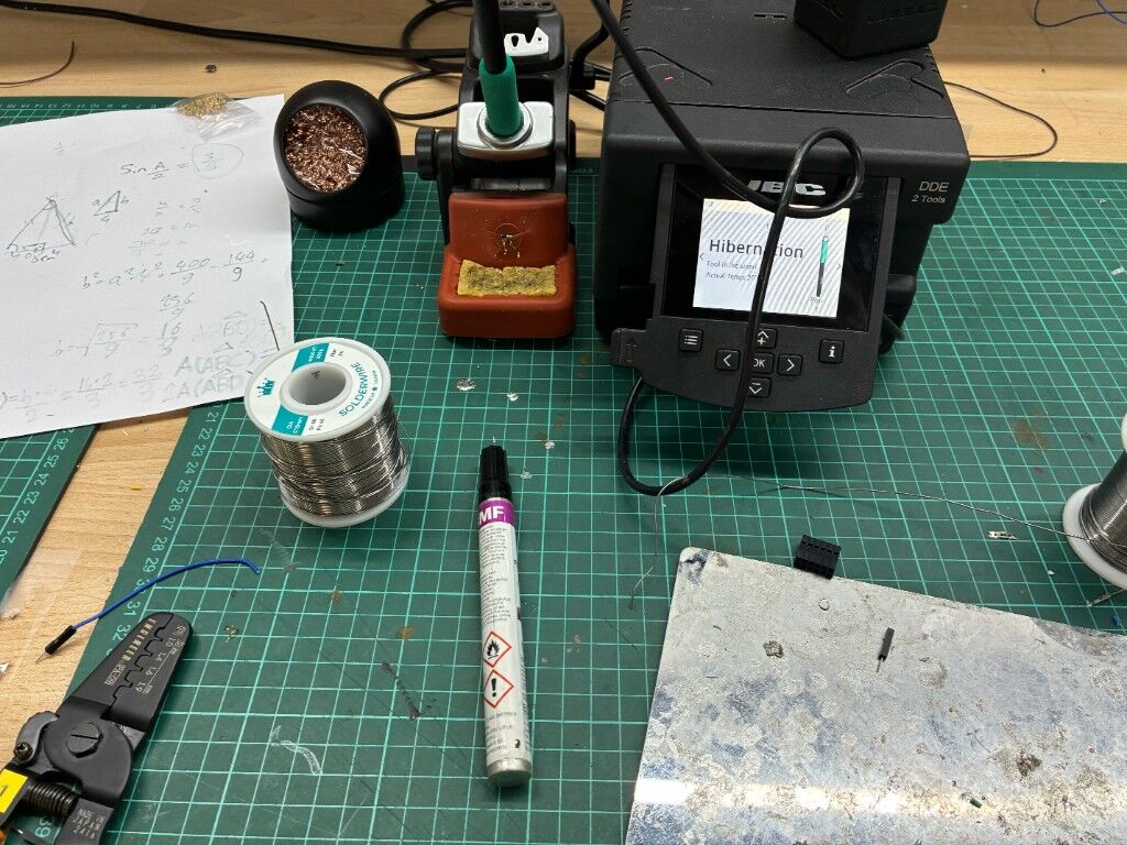
Then I used these equipments to solder I used flux soldering wire and some Isopyropyle alchool to clean the flux a pair of tweezers and pcb holder
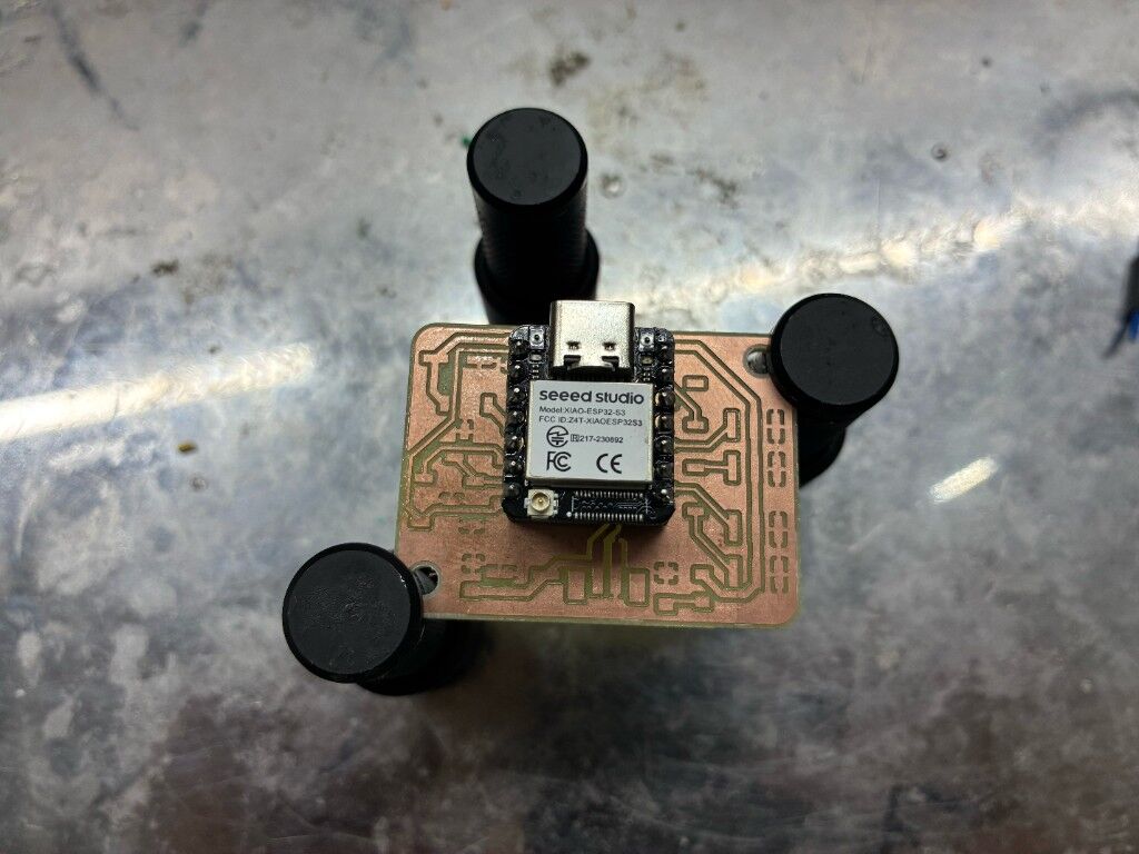
I used XIAO as a guide to solder the female pins to pcb board
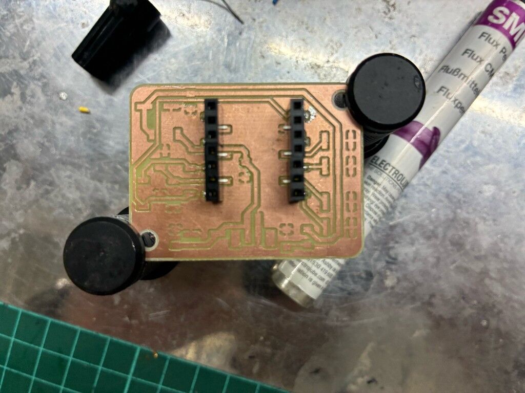
Then I carefully removed the xiao board to solder the inner pins
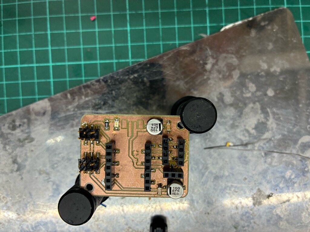
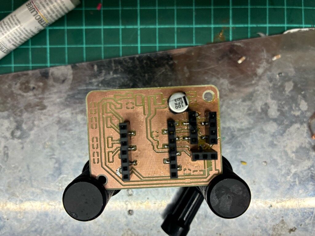
then I soldered the rest of the components
Here is a video of me soldering
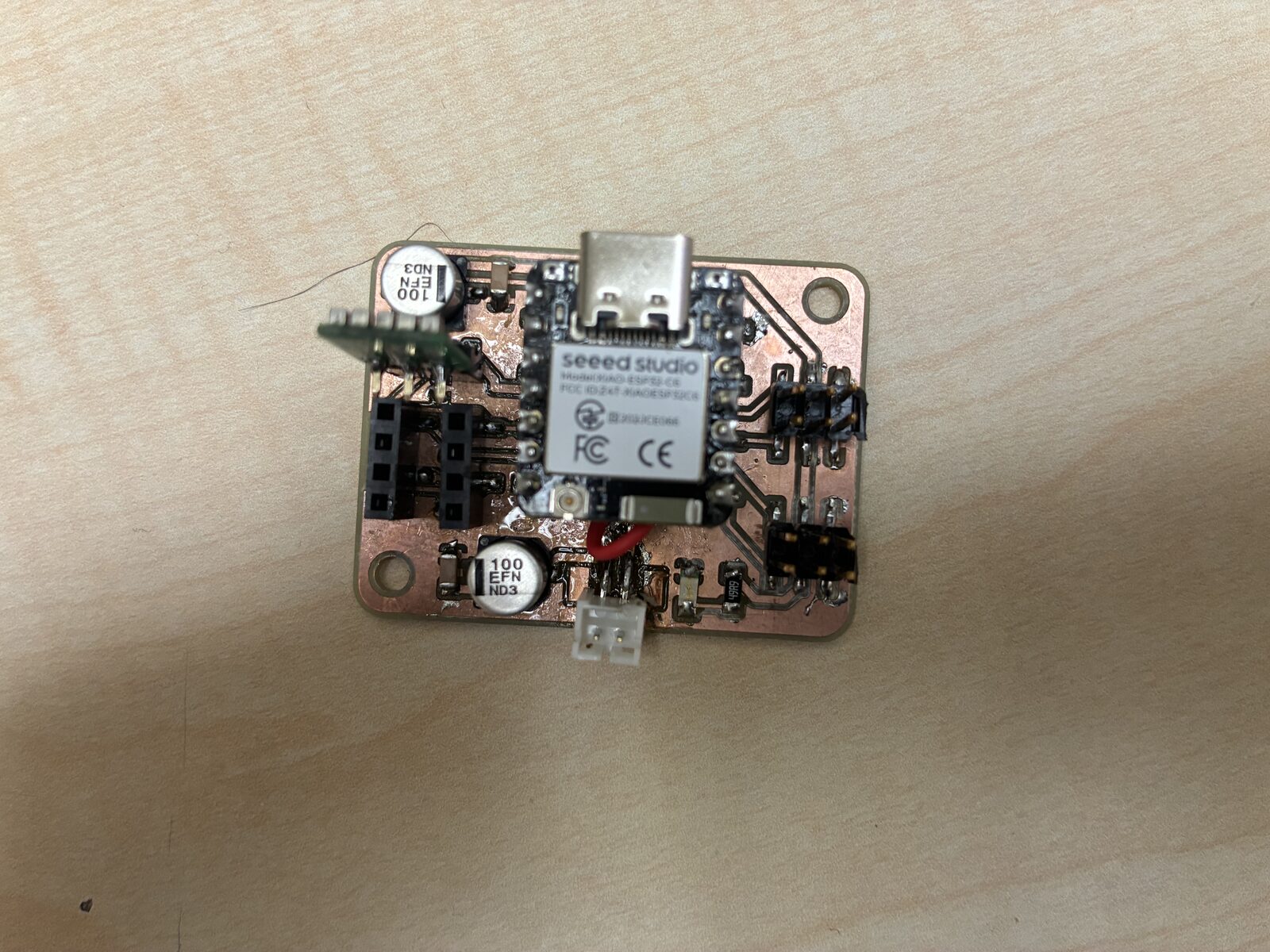
This is how the final result looked like
Testing
So For testing I used the esp32servo libraries example knob code:
/*
 Controlling a servo position using a potentiometer (variable resistor)
 by Michal Rinott <http://people.interaction-ivrea.it/m.rinott>

 modified on 8 Nov 2013
 by Scott Fitzgerald

 modified for the ESP32 on March 2017
 by John Bennett

 see  http://www.arduino.cc/en/Tutorial/Knob for a description of the original code

 * Different servos require different pulse widths to vary servo angle, but the range is
 * an approximately 500-2500 microsecond pulse every 20ms (50Hz). In general, hobbyist servos
 * sweep 180 degrees, so the lowest number in the published range for a particular servo
 * represents an angle of 0 degrees, the middle of the range represents 90 degrees, and the top
 * of the range represents 180 degrees. So for example, if the range is 1000us to 2000us,
 * 1000us would equal an angle of 0, 1500us would equal 90 degrees, and 2000us would equal 1800
 * degrees.
 *
 * Circuit: (using an ESP32 Thing from Sparkfun)
 * Servo motors have three wires: power, ground, and signal. The power wire is typically red,
 * the ground wire is typically black or brown, and the signal wire is typically yellow,
 * orange or white. Since the ESP32 can supply limited current at only 3.3V, and servos draw
 * considerable power, we will connect servo power to the VBat pin of the ESP32 (located
 * near the USB connector). THIS IS ONLY APPROPRIATE FOR SMALL SERVOS.
 *
 * We could also connect servo power to a separate external
 * power source (as long as we connect all of the grounds (ESP32, servo, and external power).
 * In this example, we just connect ESP32 ground to servo ground. The servo signal pins
 * connect to any available GPIO pins on the ESP32 (in this example, we use pin 18.
 *
 * In this example, we assume a Tower Pro SG90 small servo connected to VBat.
 * The published min and max for this servo are 500 and 2400, respectively.
 * These values actually drive the servos a little past 0 and 180, so
 * if you are particular, adjust the min and max values to match your needs.
 */

// Include the ESP32 Arduino Servo Library instead of the original Arduino Servo Library
#include <ESP32Servo.h>

Servo myservo;  // create servo object to control a servo

// Possible PWM GPIO pins on the ESP32: 0(used by on-board button),2,4,5(used by on-board LED),12-19,21-23,25-27,32-33
// Possible PWM GPIO pins on the ESP32-S2: 0(used by on-board button),1-17,18(used by on-board LED),19-21,26,33-42
// Possible PWM GPIO pins on the ESP32-S3: 0(used by on-board button),1-21,35-45,47,48(used by on-board LED)
// Possible PWM GPIO pins on the ESP32-C3: 0(used by on-board button),1-7,8(used by on-board LED),9-10,18-21
int servoPin = 19;      // GPIO pin used to connect the servo control (digital out)
// Possible ADC pins on the ESP32: 0,2,4,12-15,32-39; 34-39 are recommended for analog input
// Possible ADC pins on the ESP32-S2: 1-20 are recommended for analog input
#if defined(CONFIG_IDF_TARGET_ESP32S2) || defined(CONFIG_IDF_TARGET_ESP32S3)
int potPin = 10;        // GPIO pin used to connect the potentiometer (analog in)
#elif defined(CONFIG_IDF_TARGET_ESP32C3)
int potPin = 4;         // GPIO pin used to connect the potentiometer (analog in)
#else
int potPin = 34;        // GPIO pin used to connect the potentiometer (analog in)
#endif
int ADC_Max = 4096;     // This is the default ADC max value on the ESP32 (12 bit ADC width);
                        // this width can be set (in low-level oode) from 9-12 bits, for a
                        // a range of max values of 512-4096

int val;    // variable to read the value from the analog pin

void setup()
{
	// Allow allocation of all timers
	ESP32PWM::allocateTimer(0);
	ESP32PWM::allocateTimer(1);
	ESP32PWM::allocateTimer(2);
	ESP32PWM::allocateTimer(3);
  myservo.setPeriodHertz(50);// Standard 50hz servo
  myservo.attach(servoPin, 500, 2400);   // attaches the servo on pin 18 to the servo object
                                         // using SG90 servo min/max of 500us and 2400us
                                         // for MG995 large servo, use 1000us and 2000us,
                                         // which are the defaults, so this line could be
                                         // "myservo.attach(servoPin);"
}

void loop() {
  val = analogRead(potPin);            // read the value of the potentiometer (value between 0 and 1023)
  val = map(val, 0, ADC_Max, 0, 180);     // scale it to use it with the servo (value between 0 and 180)
  myservo.write(val);                  // set the servo position according to the scaled value
  delay(200);                          // wait for the servo to get there
}
Here is a video of it working